
Abstract
Through to the mixer of the selection of each component analysis and introduction, aiming at 10 in the desulfurization denitration common specifications of the limestone slurry tank, mixer technology selection on the optimization design, analyzes how to do in the desulfurization denitration limestone slurry tank mixer optimization selection, so as to achieve the optimal land use effect and the technological requirement. The operation performance of the mixer is directly related to the quality, energy consumption, and production cost of the product. The engineering and academic circles have attached great importance to the mixing, conducted a lot of research work, and achieved a lot of research results. But in fact, stirring process is often accompanied by reaction process, its complexity lies in its principle involves flow field, fluid mechanics, heat transfer, mass transfer, and chemical reaction and other processes. In addition to the complexity of the material flow in the mixing equipment, it is a very complex mixing state, mixing effect is difficult to quantify through the form and size of the mixer, so as to complete under a strict theoretical guidance. At present, the selection of mixer and the design of its internal components are largely dependent on experiment and practical engineering experience. The advantages and disadvantages of product design can make the benefit of mixing equipment is very different, so on the basis of clear limestone slurry material properties, for each element of mixing equipment, such as the shape of the impeller, impeller diameter, layout layer number, speed, mixing shaft size, baffle size, and number of one optimization. By making full use of the comparative analysis of existing achievements, the design and selection of 10 common specifications and models of limestone grout box are optimized, so that the design theory of mechanical mixer is more perfect, and it can also meet the requirements of practitioners in the daily desulfurization and denitration industry on the selection of limestone grout box mixer.
Introduction
In today’s desulfurization and denitration industry, mixer is an indispensable equipment, and it is widely used. Limestone-gypsum flue gas desulfurization and denitration technology has been applied in major power plants and steel mills for more than 30 years. Limestone-gypsum flue gas desulfurization and denitration technology has gradually approached perfection. In this technology, the most core equipment is limestone slurry box, which directly determines whether flue gas desulfurization and denitration is thorough. The performance of limestone slurry tank in desulfurization and denitrification depends entirely on whether the mixer it chooses is reasonable and suitable. Although many experimental and theoretical studies have been made to the blender, but the related design selection theory is still not perfect, to a large extent depends on the practical engineering experience, a few studies a class of the limestone slurry tank mixer selection technology, which makes the actual use process, and selection of the limestone slurry tank mixer is multifarious, effect is uneven. In the actual industrial production process, a large number of limestone slurry box mixers are used to magnify this defect, which brings serious cost burden and economic loss to the owners.
Through to the mixer of the selection of each component analysis and introduction, aiming at 10 in the desulfurization denitration common specifications of the limestone slurry tank, mixer technology selection on the optimization design, analyzes how to do in the desulfurization denitration limestone slurry tank mixer optimization selection, so as to achieve the optimal land use effect and the technological requirement. The operation performance of the mixer is directly related to the quality, energy consumption, and production cost of the product. In addition to the complexity of the material flow in the mixing equipment, it is a very complex mixing state, mixing effect is difficult to quantify through the form and size of the mixer, so as to complete under a strict theoretical guidance. At present, the selection of mixer and the design of its internal components are largely dependent on experiment and practical engineering experience. The advantages and disadvantages of product design can make the benefit of mixing equipment is very different, so on the basis of clear limestone slurry material properties, for each element of mixing equipment, such as the shape of the impeller, impeller diameter, layout layer number, speed, mixing shaft size. By making full use of the comparative analysis of existing achievements, the design and selection of 10 common specifications and models of limestone grout box are optimized, so that the design theory of mechanical mixer is more perfect, and it can also meet the requirements of practitioners in the daily desulfurization and denitration industry on the selection of limestone grout box mixer.
Now desulfurization denitration in the industry, the mixer design selection, many are not professional engineer, often in a blender choice, can only follow the knowledge in the books and steps from the book, although also can achieve the final purpose, but there are a lot of energy waste phenomenon, such as “small mara carts, mara car” phenomenon is commonplace. In fact, the mixing process is often accompanied by the reaction, mixing, fusion process, for different process, the choice of blender needs are not the same. For example, in the selection of flocculation tank mixer for desulfurization and denitration, according to the calculation of stirrer speed in the mechanical manual, the critical stirring speed of solid suspension in the cylinder under the condition of no baffle, once the diameter is less than 5 m, the speed must be 50–70 r/min and above. In the actual use process, due to the need to add flocculant flocculation tank, the required speed cannot be too high. Because once the speed is too high, it will make the stirring blade produce huge shear force, resulting in the fracture of the flocculant, so that the flocculation tank lost the significance of setting and original intention. In this case, it is necessary to reduce the speed of the mixer in the flocculation tank to less than 30 r/min, but in order to achieve the purpose of solid-liquid suspension and meet the requirements of initial liquid discharge, the mixer blade must be enlarged at this time. Therefore, it is of practical significance to study the type selection of blender for a specific medium tank.
According to the industry standard 《HG/T 3796.1 – 2005》, there are as many as 61 standards for stirring blades, including inclined blade, three-blade, four-blade, anchor, frame and other types, plus special forms of blades designed to cope with special working conditions, so the types are more diverse. In 《HG/T 3796.1 – 2005》, there are as many as 19 kinds of standard introduction of stirring shaft. However, in actual use, there are solid shaft and tube shaft, integral shaft, and segmental shaft. Due to the variety of the selected range, it will cause serious trouble to the designer in the actual selection process.
Based on in power plant desulfurization denitration industry work experience for many years, the effects on the limestone slurry tank mixer, starting from the existing successful results, analysis, and research on the 10 of the most common kind of optimization in the selection of the limestone slurry tank mixer, in order to choose for the limestone slurry tank mixer after provide valuable advice and experience.
Working conditions of limestone slurry tank
According to the data, the density of limestone grout in desulfurization and denitrification is more than 1300 kg/m3, and the solid content is more than 30%. The specific solution medium parameters of limestone slurry are shown in Table 1.
Operating environment of limestone slurry tank.

The diameter (m) of the 10 limestone slurries in this study is: φ1 × 1; φ2 × 2; φ3 × 3; φ4 × 4; φ5 × 5; φ6 × 6; φ7 × 7; φ8 × 8; φ9 × 9; φ10 × 10.
General mixer design procedures can be shown in Figure 1.
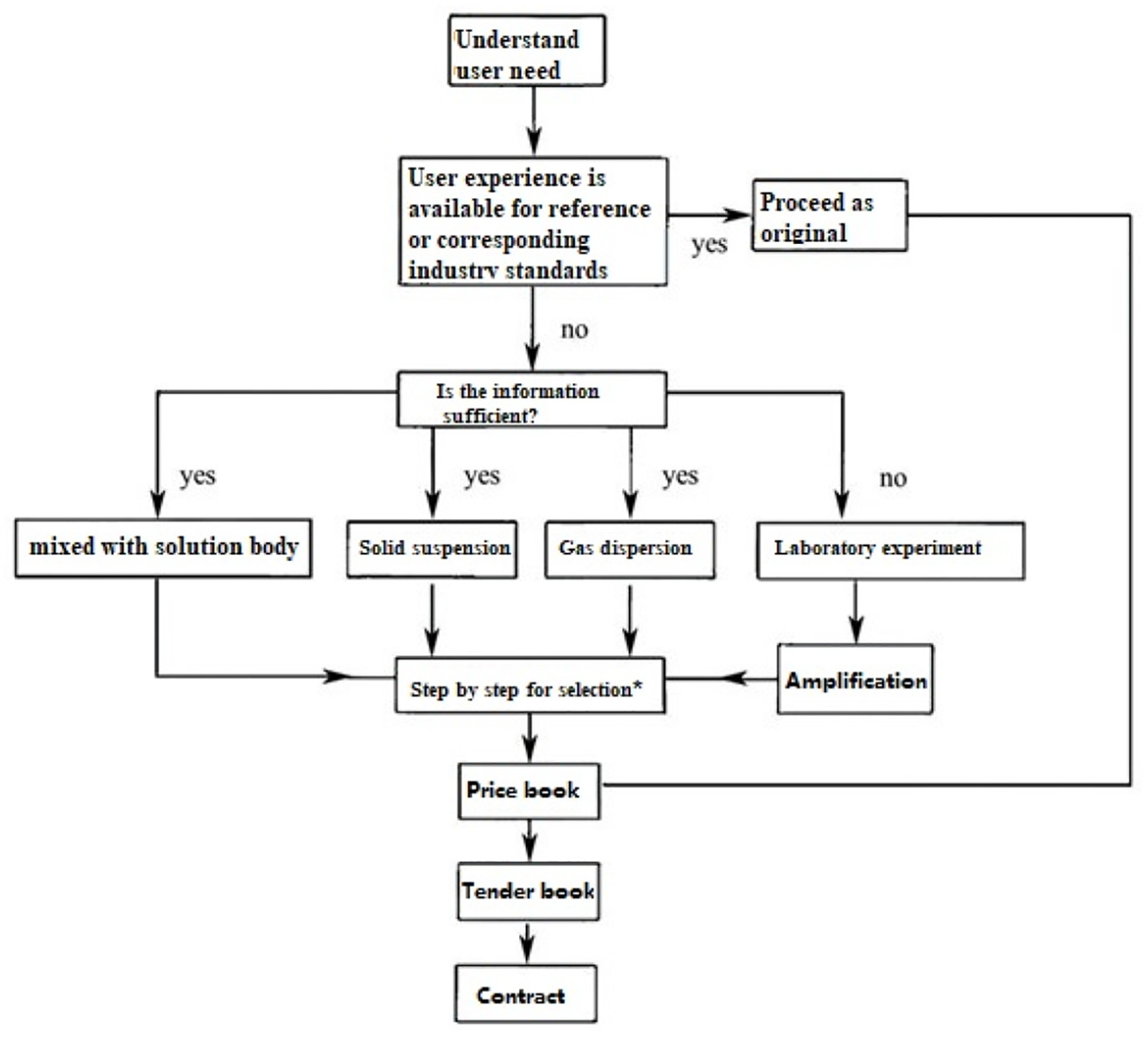
Block diagram of mixer design.
Agitator speed
The calculation formula of agitator speed is shown in equation (1).

Where, K is the coefficient, and the reference value is 187–263, generally selected is 263. D is the inner diameter of the stirring tank, m; dp is solid particle diameter, mm; Δρ is the density difference between solid particles and liquid, g/cm3;
For solid-liquid solution, besides solid suspension, mass transfer is also a priority. For mass transfer problems, the intensity of agitation can be compared with the dissolution velocity coefficient or the thickness of the diffusion boundary layer. 1 According to the laboratory data, there is a critical stirring speed relationship for solid and liquid solution agitation. When the speed of the mixer is below the critical speed, the solid dissolution speed accelerates with the increase of the stirring speed. Once the critical speed is reached, the effect of increasing the speed of the mixer on the solid dissolution speed is limited. It is generally believed in the industry that agitation has a weak influence on the mass transfer coefficient. The main function of agitation is to suspend all solid particles and increase the mass transfer rate by increasing the mass transfer area between solid and liquid. 2 Therefore, once the mixer reaches the critical speed, it is not of great practical significance to suspend the solid particles deposited at the bottom and then improve the mixing speed. For the purpose of setting up the limestone slurry box mixer, it is not necessary for the solution to reach the uniform state of solid and liquid, as long as the solid particles at the bottom of the plankton phenomenon. Excessive stirring intensity will only lead to waste of stirring power, which is not very effective for limestone dissolution process.
Blade type and blade diameter
The stirring action of the mixer is produced by the moving impeller. Therefore, the shape, size, number, and speed of the impeller affect the mixing effect of the mixer. Generally speaking, the function of limestone mixer is to provide energy and suitable flow state for limestone dissolution to achieve the purpose of the whole mixer. According to different diameter of the limestone slurry tank, this study set up five different types of blades, respectively is: three narrow leaf detachable plate propeller (ZCX), three oblique leaf detachable open turbine (YCK), four oblique leaf detachable open turbine (XCK), double oblique leaf removable paddle (XCJ), and double circular arc helical lobe removable paddle (HXCJ). The blade processing diagram is shown in Figures 2 to 5.

Processing drawing of ZCX with three narrow blades (unit/mm).

Three oblique blade detachable open turbine (YCK) processing drawings (unit/mm).

Four oblique blade removable open turbine type (XCK) processing drawings (unit/mm).
Double oblique blade detachable paddle (XCJ) machining drawings (unit/mm).
The impeller forms are generally divided into radial flow and axial flow. The selected blades in this study are axial flow blades. Due to the particularity of the blade structure, their surface is inclined to a certain Angle θ with the movement direction. This drainage feature allows for a good mix of limestone grout for better use.
The diameter of the blades is generally one-half–one-fifth of the diameter of the reaction kettle. Considering that the blades are mostly combined this time, the diameter of the blades of the 10 limestone slurry box mixers are respectively selected as: 500, 800, 1150, 1400, 1600, 1900, 2100, 2500, 2800, 2900 mm. Specific statistics of blade types and blade diameters are shown in Table 2.
Blade diameter statistics table.

Mixer motor power
The calculation formula of motor power is shown in equation (2)

Where, Np is the power criterion; ρ is the density of stirring medium, g/cm3; n is stirring shaft speed, r/min; Dj is the blade diameter, m.
The stirring process needs power, and the power source is three-phase asynchronous motor. Np is the coefficient and is related to the Reynolds number Re. Desulfurization and denitrification industry, generally according to the empirical value of 0.81 calculation. Consider the motor service coefficient fb, ensure 1.2 ≤ FB ≤ 2.0. When the stirring container is small, 1.5 ≤ Fb ≤ 2.0 can be selected; When the stirring container is large, 1.2 ≤ Fb ≤ 1.5 can be selected. After calculation, the motor power of 10 specifications of limestone slurry box mixer is selected as: 2.2, 3, 5.5, 7.5, 11, 15, 22, 30, 37, 45 kW. Compared with the existing performance, the power is not much different, which also confirms the correctness of the selection.
Generally speaking, the start of the mixer must overcome the inertia of the liquid, especially for the limestone slurry box mixer, the blade is mostly multi-leafed or double-layer arrangement, which will definitely make the mixer directly push the amount of still liquid. In order to overcome the liquid inertia during the motor’s starting process, the starting torque will reach a peak momentarily, and then drop to a stable operating torque. At the same time, the speed of the stirring shaft approached the rated speed soon after starting, and then gradually increased to a stable value. 3 Because there are instantaneous peaks, although the duration is short, this problem cannot be ignored. The three-phase asynchronous motor has its allowable starting overload, allowing a wide range of starting current, so it is the most suitable motor type for this limestone slurry box mixer. When the three-phase asynchronous motor starts, it relies on the torque allowance to accelerate the liquid and stir the impeller until it reaches a stable working speed, which will not cause the motor overheating or failure to start. 4
In this study, the motor of limestone slurry box mixer is YE3 series motor, grade 4 motor, synchronous speed 1500 r/min, energy efficiency grade meets national grade 2 energy efficiency GB 18613.2012, protection grade: IP55, insulation grade: F, temperature rise grade: B. The physical picture of the motor is shown in Figure 6.

Physical drawing of three-phase asynchronous motor.
Stirring shaft diameter
The calculation formula of stirring shaft diameter (D, unit mm) is shown in equations (3)–(4).


Where, M is the stirring shaft torque, Nm; P is the stirring shaft power, kW; n is stirring shaft speed, r/min; η is the transmission efficiency, η = 0.95; γ is allowable torsion Angle, (°)/m, γ = 0.35(°)/m; E is shear elastic modulus, MPa, E = 79,000 MPa.
In order to prolong the service life of the limestone slurry tank mixer and avoid damage to the shaft and equipment, two types of mixing shafts were selected in this study: solid shaft and tube shaft. For stirring shaft, the smaller the design deflection of stirring shaft, the greater the stiffness will be. The agitator shaft selected in this study has a margin on the calculated value, and adopts the form of stepped shaft, which not only reduces the deflection of the agitator shaft, but also greatly improves the critical speed value of the agitator shaft. The higher the critical speed, the higher the stability of the agitator shaft, the greater the safety factor and the better the rigidity. After calculation, the diameter of mixing shaft of 10 specifications of limestone slurry box mixer is selected as: 50 mm, 60 mm, 80 mm, 90 mm, 125 mm × 16 mm, 140 mm × 16 mm, 168 mm × 18 mm, 194 mm × 18 mm, 219 mm × 20 mm, 219 mm × 20 mm.
Cantilever shaft length: 900, 1900, 2700, 3700, 4700, 5700, 6700, 7700, 8400, 9400 mm. Specific statistics of stirring shaft diameter specifications are shown in Table 3.
Statistical table of stirring shaft diameter.

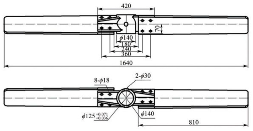
With the increase of the length of the mixing shaft, the disturbance of the mixing shaft increases, the rigidity decreases, and it is easy to fracture. However, it is difficult to process the shaft in sections, and the production cost is high. Therefore, it is not necessary for some stirring shafts with smaller shaft length. Through the actual processing plant production experience, cantilever shaft length is generally 5 m appropriate, more than 5 m of the shaft should be segmented processing, separate processing into two sections of shaft, with flange connection in the middle. The processing drawings of the tube shaft are shown in Figures 7 and 8.

Processing drawing of tube shaft-upper (segmented shaft) unit mm.
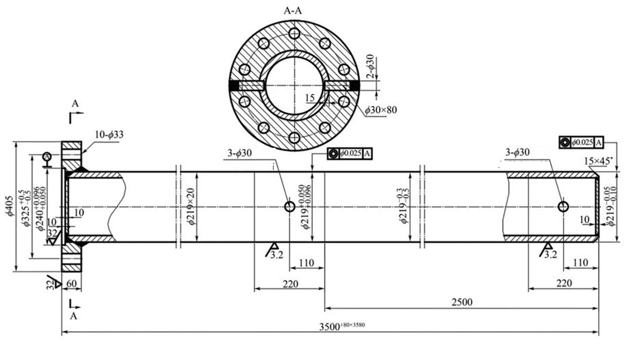
Processing drawing of tube shaft-bottom (segmented shaft) unit mm.
Computational load
The static and dynamic loads, torques and bending moments of 10 limestone slurry box agitators are calculated by formulas, as shown in equations (5)–(8).


Where, m is the agitator mass, kg; H is the cantilever length, mm; η is the transmission efficiency, η = 0.95, Dj is the blade diameter, m, n is the stirring shaft speed, r/min.
After calculation, the load statistics of 10 limestone grout box mixers are shown in Table 4.
All kinds of mixer load statistics.

Transmission mechanism
The mixer has a separate transmission mechanism, which includes a reduction device and a coupling.
With the development of industry, there are various types of reducer on the market. In the flue gas desulfurization and denitration industry, the use of more types are: spur gear reducer, helical gear reducer, belt reducer, cycloid needle tooth planetary reducer, etc. Through the comparison of actual use and error rate, helical gear reducer has the highest cost performance. The helical gear reducer runs smoothly, and its working state is more stable and reliable in the case of vibration and load changes. Helical gear reducer is arranged by one or more groups of bevel gear meshing, shape height size is small, very suitable for indoor layout, or the upper installation space is limited. Through transmission ratio, power, inlet and outlet shaft speed, use coefficient, 10 specifications of limestone slurry box mixer reducer are selected as MKF47, MKF57, MKF77, MKF87, MKF97, MKF107, MKF107, MKF137, MKF157, MKF157. Specific statistics of reducer specifications are shown in Table 5.
Reducer specification statistics sheet.

The purpose of using the coupling is to connect the mixing shaft and the reducer output shaft two independent individuals into a whole, used for rotation and transfer of motion, power. Another function of the coupling is to minimize the transmission of sudden loads, such as vibrations or shocks, to one party. In view of this, the rigid flange coupling is selected in this study, which is composed of two semi-couplings with convex and concave disks. The two half couplings are both related and relatively independent. They are secured circumferentially by flat keys and axially by locking nuts. Once locked, torque is transferred by friction. A half coupling end face is processed into a convex shoulder, and the other half coupling is opened with a groove, which is fixed together with bolts after centering. The rigid flange coupling has small size, light weight, large bearing capacity, high installation accuracy, and has certain compensation for the relative offset of two shafts and general shock absorption performance. Rigid flange coupling shaft also has the characteristics of simple structure, convenient maintenance, long life, large transmission torque, convenient disassembly, and assembly. Specific statistics of rigid flange couplings are shown in Table 6.
Rigid flange coupling specifications statistical table.

Other attachments
Rack: The rack limestone slurry tank mixer is mounted on the head of the mixing equipment through the rack. The rack usually also needs to contain the coupling, bearing box and other components and the space required for installation operation. According to the current domestic rack standard HG 21566–19995 《Mixing Drive Device –Single Fulcrum Rack》, the reducer specifications of 10 limestone slurry box mixer are respectively selected as follows: DXJ35, DXJ45, DXJ65, DXJ80, DXJ110, DXJ110, DXJ120, DXJ140, DXJ140, DXJ160. See Figure 9 for processing drawings.
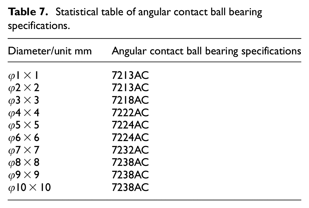
Bearing: The bearing in the bearing box is a diagonal contact ball bearing selected for this study. In the operation process of the mixing shaft, the disturbance has a great influence on its service life. Angular contact ball bearings can reduce the disturbance of the shaft end as much as possible, increase the stiffness of the mixing shaft, and control the deflection of the mixing shaft as far as possible within the allowable range. Different from general deep groove ball bearings, angular contact ball bearings because they appear in pairs, the raceways of their inner and outer rings can have relative displacement on the horizontal axis, so they can bear radial and axial loads at the same time. Angular contact ball bearings have small friction torque. Compared with other bearings of the same size, they have large dynamic and static load capacity, low temperature rise, low noise, good rigidity, and convenient disassembly and assembly. Specific statistics of angular contact ball bearing specifications are shown in Table 7.
Baffle: For the circular stirring kettle, in the process of stirring, if you rotate in the same direction for a long time, often accompanied by the phenomenon of “vortex dead zone,” these vortex dead zone, is the blind spot area of stirring, generally can not stir. At this time, it is often necessary to add baffle, especially for the limestone slurry tank, baffle can play a “spoiler effect,” with the addition of baffle, limestone slurry in the process of mixing, the sag on the slurry surface disappeared.

Rack processing drawing (unit: mm).
Statistical table of angular contact ball bearing specifications.
After the baffle is installed in the limestone slurry tank, the baffle will form a strong circulating flow up and down the wall surface and the mixing shaft. In order to distinguish it from the high-speed flow discharged from the blade, it is called the secondary circulating flow. In addition, the installation of baffles greatly reduces the circumferential velocity of slurry flow, while increases both radial and axial velocity. Some studies have shown that with the installation of baffles, the vertical circulation velocity can be four times of that without baffles. 5 Although there is no problem in the selection of many pot limestone slurry boxes, the effect is not ideal in the actual use process, and most of the baffle problem is not taken into account. With the addition of the secondary circulation flow produced by it, the mixing effect of the limestone slurry tank will be greatly improved. Three to four baffle plates are generally set in small diameter and 4–6 baffle plates in large diameter, and the diameter is generally one-twelfth of the diameter of the stirring kettle. The baffle plate Settings of 10 types of limestone slurry box agitator are shown in Table 8.
Baffle specifications statistical table.

(4) Material selection: In order to provide energy and thus cause the flow of liquid, limestone slurry tank mixer must have a reasonable structure and sufficient strength. The so-called reasonable structure will also affect the structure in addition to the selection and geometric size of impeller, and the type of material.6–11 The material of limestone slurry box mixer is mainly selected from two aspects of corrosion resistance and strength. Considering economic cost and service life, the order of material performance is generally as follows: Carbon steel lining glue < stainless steel 304< stainless steel 316L< duplex stainless steel 2205< super duplex stainless steel 2507< nickel base alloy 1.4529, the price is also the cheapest carbon steel lining glue, nickel base alloy 1.4529 is the most expensive. Carbon steel lining glue is recommended, carbon steel Q235 is used for mixing shaft and blade body, and butyl rubber no less than 6 mm thick is selected under high temperature conditions. Due to the particularity of limestone slurry box solution, solid small particles are numerous and miscellaneous, so it is necessary to ensure the complete sealing of rubber. Once there is a small crack or gap in the lining part, it is easy to cause all the lining glue to fall off. Therefore, before leaving the factory, electric spark detection must be carried out. After the electric spark detection is passed, the service life of carbon steel lining glue is also more than 15 years, which can fully meet the practical desulfurization and denitration field use.
Key technical parameters
After design optimization, the overall layout of the limestone slurry box mixer is shown in Figure 10.

Final assembly and processing drawing of limestone slurry box mixer (unit mm). 1 – Helical gear reducer; 2 – frame;3 – coupling; 4 – bolt; 5 – nut; 6 – spring washer; 7 – Stirring shaft (upper); 8 – Mixing shaft (bottom); 9 – Stir the paddle.
The limestone slurry tank mixer contains many parts, so filling in various parameters is very complicated. The key technical parameters are summarized and counted in this study. After years of practice, the application of mixer in flue gas desulfurization and denitration has been very perfect. In this paper, the author’s research group sorted out the key parameters of limestone slurry tank mixer through years of bidding experience, almost covering all the relevant data and parameter requirements that need to be filled in the bidding. See Table 9 for specific parameters. And see Figure 11 for the numerical model.
Statistical table of baffle specifications.


Limestone slurry tank mixer digital model.
Conclusion
Mixing and mixing operation is one of the most widely used process unit operations, especially in the flue gas desulfurization and denitration industry, in a variety of tanks including limestone slurry tank, gypsum slurry tank, filter pit and so on reaction kettle, mixer application everywhere. Generally, the density of desulfurization wastewater is between 1.1 and 1.3, and the solid content is less than 30%. However, the density and solid content of limestone slurry are higher than this, so the design and selection of limestone slurry tank mixer will be more difficult and complex. Limestone slurry tank is now developing toward large-scale, standardization, high efficiency and energy saving, specialization and specialization, so it is necessary to carry out a special study on limestone slurry tank mixer in this paper. The author has been working in the application industry of flue gas desulfurization and denitrification mixer for many years. He has presided over the design and participated in the design, selection, installation, and acceptance of thousands of mixers of Guodian, Huadian, and Datang, three major power groups, and accumulated rich field data and experience. This selection research also pays attention to the combination of theory and practice.
In this paper, a typical limestone slurry tank mixer is selected as the design object, and the selection and calculation of 10 types of limestone slurry tank mixing equipment and its internal components are systematically and detailedly introduced. Based on the existing achievements and successful experience at home and abroad, the selection principle and optimization method of limestone slurry box mixer are introduced comprehensively. Under the premise of meeting the normal process requirements and use requirements, the limestone slurry tank mixer is more safe, reliable, efficient, and energy saving operation. Through the introduction of processing drawings and bidding documents, it provides a reference for technical personnel in the future production and processing and participation in bidding competition, and has practical guiding.
Stirring mixing is not just simple material mixing, often accompanied by reaction, heat transfer, mass transfer, the principle involves flow field, fluid mechanics. Coupled with the complexity of material flow in the mixing equipment, so it is a very complicated mixing state. In view of this, the design and selection of limestone slurry tank mixer should not only have theoretical support, but also should learn from the existing successful achievements. The 10 specifications of limestone slurry box selected in this paper almost cover the normal specifications that can be used in desulfurization and denitration industry, which provides the basis and help for the technical personnel to learn from the existing experience in the process of selection. It also provides some reference for the medium mixing with high density and high solid content such as limestone grout.
In actual engineering practice, for the selection of limestone slurry tank mixer, it mostly relies on successful experience and cases at home and abroad, or after successful experiments in the laboratory, it is then enlarged in the same proportion. This article selects 10 kinds of limestone slurry tank specifications with reference to the previous successful performance, these specifications almost cover the common sizes of limestone slurry tanks that can be seen in the desulfurization and denitrification industry, which can help designers and technicians to quickly locate and select references.
Footnotes
Handling Editor: Chenhui Liang
Declaration of conflicting interests
The author(s) declared no potential conflicts of interest with respect to the research, authorship, and/or publication of this article.
Funding
The author(s) received no financial support for the research, authorship, and/or publication of this article.