
Abstract
An elevator traction system is simplified as a damped vibration system. In order to study the damping characteristics of an elevator traction system, this paper tests the vibration characteristics of a car frame on an in-service elevator with a traction ratio of 2:1. The results show that the natural frequency and stiffness of the system decrease with the increase of the elevator load; the attenuation coefficient and damping increase with the increase of the elevator load; Furthermore, the damping of the traction system is related to the initial running direction. Under the same load, the damping value of downward is greater than that of upward. This research establishes the relationship between vibration parameters, load and elevator running direction and provides an approach to solve the problem of quantitative measurement of damping in the process of elevator operation. Results from this study can provide reference for elevator vibration analysis.
Introduction
Elevator is a complex mechanical and electrical equipment, and its traction system has the characteristics of flexible structure. 1 Advancements of the science and technological development, as well as the trend of the development of high-rise buildings, have consequently developed a need for high-speed elevators with pronounced dynamic loads, 2 what causes a problem of the right choice and definition of basic parameters of the elevator, especially regarding their reliability, comfort, and safety. The basic parameters of the system are not only related to the sensitivity of the system to vibration after excitation, but also a direct reflection of the comprehensive performance of the elevator. Therefore, the basic parameters of the system are of great significance to study the vibration characteristics of elevator.
The structure of the elevator traction system is shown in Figure 1. The elevators are used to interconnect different floors horizons by using a car (which is moved between at least two firmly set guide rails), whose dimensions and construction enable to transport people and goods. The static friction between the traction wheel and the steel wire rope is the driving force for the movement of the car. The traction elevator is widely used because of its low energy consumption, simple structure, and other advantages.
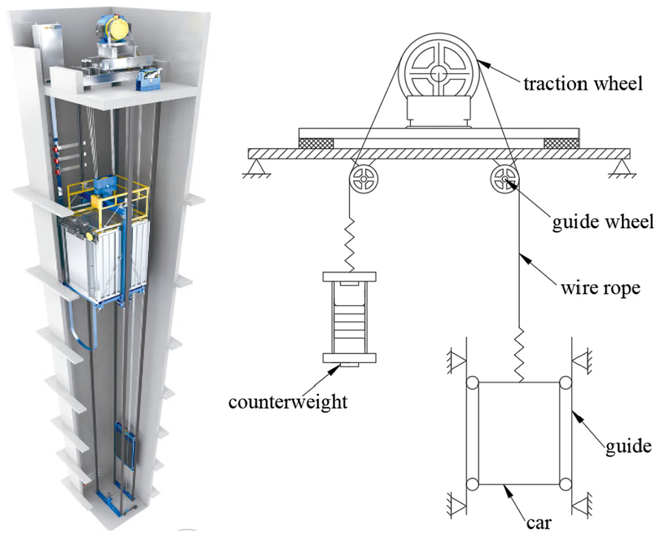
Illustration of elevator traction system.
Correctly selecting and defining the basic parameters of elevator is of great significance to the comfort and safety of elevator. The friction characteristics of the rails and the slide guide are very important. Zhang et al. examined the properties of the friction contact between the interface of the slide guide and rail of elevator systems through experimental. Under different input combinations of parameters, the contact friction between the sliding guide rail and the guide rail contact surface is measured. 3 For high-speed elevators, the car aerodynamic characteristics have an obvious effect on the running stability of the elevator. Qiu et al. 4 studied the influence of aerodynamic parameters on the horizontal vibration of high-speed elevator which can improve the ride comfort of elevator. Zhang et al. studied the influence of the three parameters such as the length, weight per unit length, and the bending stiffness on the dynamic characteristics of the guide rail. The results reveal the inherent law between structural parameters and dynamic characteristics, which will provide theoretical guidance for the manufacture and selection of guide rails and the design of the elevator. 5 In Gaiko and van Horssen’s paper, the lateral vibrations and resonances emerging in an elevator cable system due to the excitation at its boundaries initiated by the wind-induced building sway were studied. This study helps to improve the safety of elevators in the event of an earthquake. 6 In Fan and Zhu’s paper, effects of vertical motion of the car on free responses of the traveling cable and those of in plane and out-of-plane building sways on forced responses are investigated. In addition, the relationship between frequencies and the corresponding mode shapes of cable at different car positions is also calculated. 7 Peng et al. uses the centralized mass discretization model to study the response characteristics of elevator under normal operation and emergency braking conditions. This model can be used to analyze the braking performance of elevator and has important reference value for the research on the safety performance of elevator traction system. 8 Wolszczak et al. studied the nonlinear mechanical problems of elevator braking system under the action of uncertainty. Based on the condition of mechanical balance, the deterministic model between braking force and uncertain parameters is derived. 9 During the operation of the elevator, the physical parameters change with time. Zhang et al. 10 established a nonlinear time-varying model of the longitudinal vibration of the lifting steel wire rope by using Hamilton principle and energy method, and studied the influence of the time-varying characteristics of the traction system on the longitudinal vibration of the elevator. Kumar et al. 11 extracts the system eigenvalues by testing the acceleration signal of the system, and uses the convolutional neural network method to achieve the purpose of real-time monitoring the health state of rotating machinery bearings. Scholars have done a lot of research on the relationship between elevator operating parameters and ride comfort and safety, and have achieved rich research results in the field of dynamics of lifting system. However, due to the time-varying characteristics of the lifting system and the uncertainty of the lift car load, the inherent properties of the lifting system are constantly changing, and its dynamic characteristics need to be studied as a whole.
Stiffness and damping, are important parameters of the model and due to the complexity of elevator engineering environment, the process of defining these parameters is very complicated. When the system resonates, the amplitude is significantly affected by damping. However, it is difficult to directly measure the damping and attenuation coefficient of vibration system. In addition, it is difficult to carry out damping test on service elevators because of the limitation regarding of elevator safety protocols. In this paper, the method of emergency braking is used to excite the system, so that the system can do vibration with damping. Through the method of free vibration attenuation, the relationship of the system vibration parameters under the conditions of different loads and different directions of operation is studied. This method measures the inherent properties of the elevator under the conditions of different loads and different running directions. When the damping is small, the test method has the advantages of high accuracy and less equipment. In order to improve the operation performance of elevator, reference3–6 studies the relationship between elevator operation parameters (such as guide rail contact friction, guide rail structure parameters, building shaking, and other factors) and elevator dynamic characteristics. However, few scholars have studied the influence of the inherent properties of the traction system (car load, stiffness, and damping) on the vibration of elevator system. Damping parameters, like other parameters of vibration system, are important references to judge whether the system operates normally. The results from this study can be used as input parameters, combined with artificial intelligence method, in the field of equipment health monitoring and fault diagnosis.12–14
Calculation of free vibration damping of traction system
The characteristic features of elevators are reflected in high lifting heights up to hundreds of meters and the maximum velocity up to 20 m/s. This paper studies an elevator traction system only for the elevator car side, including guide wheel, wire rope, car. If the elevator is in regular operation, there is no slip between the wire rope and the traction wheel, that is, the speed of the traction wheel is the same as that of the wire rope. As it was mentioned before, the model of the elevator can be represented in the form shown in Figure 2. This model shows a system with longitudinal oscillations of the steel rope with an infinite number of degrees of freedom, which is at one end fixed on a pulley, while it is loaded with a concentrated mass on the other end.

Vibration model of traction system.
Deformation of the arbitrary cross section is represented as a function of position x and time t:

By observing the balance of the elementary part (dx), formula (2) can be obtained:


The above two equations are combined to obtain:
where: ρ− rope density, E− elasticity modulus, MPa; S− rope cross-section, mm2; u− rope elastic deformations, mm;
We can use the method of separating variables and the solution of the equation (4) can be seen as a multiplication of the two functions, where one is a position function and the other is a time function, in the following form:

According to the boundary conditions of the model, the frequency equation can be obtained:

with:

The solution of transcendental equation (6) with different mass ratio can be obtained by numerical calculation method. It has an infinite number of roots, because the model has infinite degrees of freedom.
If the concentrated mass at one end of the wire rope is large, the analysis of the dynamic behavior of elevators is greatly simplified.
When β is much smaller than 1, the fundamental frequency of the system is as follows:

where:
This result is the same as that of the single degree of freedom system. It shows that when calculating the fundamental frequency, if the mass of the wire rope is very small compared with the additional mass at the end, it can be ignored. Table 1 shows the relationship between the theoretical value and the simplified value of fundamental frequency with different β values.
Relationship between theoretical value and simplified value.

As described in the previous, an elevator car can be considered as a rigid body with large mass and the natural frequency of this structure is small. The first natural frequency can reflect the main vibration characteristics of the car frame. Therefore, the influence of higher harmonics on the system can be neglected. In this case a system with an infinite number of DOF can be satisfactorily accurate if replaced with one DOF.
Stiffness is an important parameter of the vibration system. According to the structural characteristics of the elevator traction system, the stiffness can be defined as the following formula:

where, i is the traction ratio, n is the number of wire rope, l is the length of wire rope from the top of the car frame to the tangent point of the traction wheel. The parameters
As a suspension system, the movement of elevator traction system in the shaft will be affected by damping force. In the dynamic analysis of traction system, damping force is a factor that can’t be ignored.
According to the vibration theory, when 0

In the formula, the parameters

The parameter

The natural period of the damped vibration system is:

The amplitude of damped system attenuates exponentially in the process of vibration. The logarithmic decrement rate δ is used to represent the natural logarithm of the ratio of two adjacent amplitudes in a natural period.

According to the simultaneous formulas (8), (11), and (14)

Free vibration damping test scheme and equipment parameters of traction system
Damping test has two typical test methods: half power bandwidth method and free vibration attenuation method. 15 Since an elevator in use runs in a narrow elevator shaft, generally it is more than 1 ton, it is impossible to install vibration exciter on the car roof by using the half power bandwidth method. For this reason, the half power bandwidth method is not suitable for elevator damping test. The free vibration attenuation method is realized by testing the free vibration curve of the system. Due to the damping effect, the amplitude of vibration will gradually decrease over time, and finally approach zero and stop vibration. Damping is a parameter directly related to the attenuation coefficient. For a single degree of freedom system, the damping can be calculated from the test results by using the free vibration attenuation method.16–19
In order to obtain external interference while complying with elevator safety protocols. When the normal operation of the elevator reaches the rated running speed, the traction system is stimulated to make free vibration by emergency braking of the traction machine. The acceleration sensors were installed on the car frame, and the free vibration acceleration attenuation curves were obtained by recording the vibration attenuation process waveform of the elevator. In order to study the relationship between the vibration parameters of the traction system and the change of different loads and running directions, 300, 400, 500, 600 kg weights were loaded in the car respectively.
Test method and main test equipment
At the beginning of the test, firstly, when the elevator is up to the middle of the travel at a uniform speed, the power is cut off to make the elevator brake emergency. After recording the test data, the elevator returns to normal and then runs to the top of the floor. The downward emergency braking operation is consistent with the upward emergency braking operation. When the elevator returns to normal, run to the bottom floor, move the weight to the specified weight, and repeat the above steps until it is completed. Finally, collect test data and process the data. The test procedure is shown in Figure 3.

Test process and experimental setup.
Mass is one of the important parameters of vibration system. Due to the heavy weight of the car and the lack of space in the elevator shaft, it is very difficult to weigh the car. The weight measuring equipment (Figure 4) is developed by us. It is composed of upper fixture and lower fixture. Fix the weight measuring equipment on the wire rope. Adjust the screw so that the upper and lower fixtures are close to each other. When the wire rope is completely relaxed, the car mass can be measured.
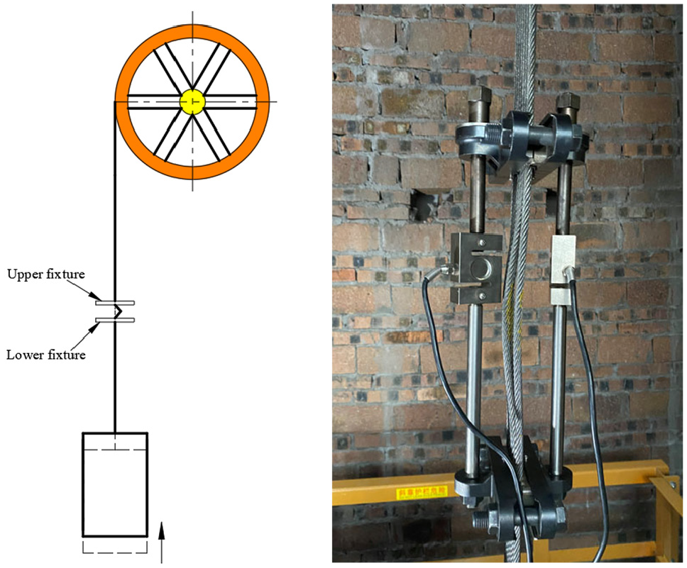
The weight measuring equipment.
In order to measure the acceleration of the elevator in the process of emergency braking, ASC single axis capacitive acceleration sensor is used in the test. Capacitive sensor has the advantages of simple structure, small volume, high resolution, and good dynamic response, 20 and its mass is only 10 g, so the impact of the sensor on the test system is negligible. Acceleration sensor parameters are shown in Table 2. Figure 5 shows the sensor installation location and equipment layout of the project site. After the staff fixed the sensor and the experimental device on the top of the car frame, they left the car top, and professional elevator maintenance personnel performed emergency braking operations in the elevator machine room.
Parameters of single axis capacitive accelerometer.


Acceleration test.
Test elevator parameters
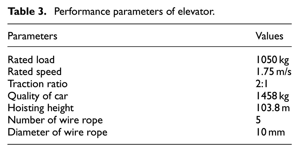
The test elevator is a passenger elevator with lifting height of 103.8 m and traction ratio of 2:1. The specific parameters of the elevator tested are shown in Table 3.
Performance parameters of elevator.
Analysis of experimental results
Vibration curve of car frame after stopping
In the actual working conditions of the elevator, the diagrams of car acceleration and damping oscillation can be obtained by the method of emergency stop (Figure 6). From the diagrams, the attenuated vibration period
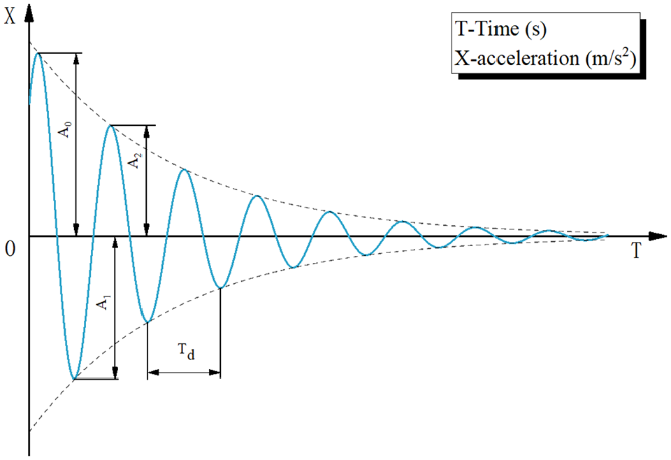
Attenuation vibration curve of elevator frame after upward braking.
Analysis of upward test results
When the traction machine is completely braked, the car frame begins to vibrate with damping. The free vibration stage is a typical case of small damping. Due to the characteristics of the elevator, the test process (Figure 7(a)) is divided into three stages: variable speed phase (P1), constant speed phase (P2), and emergency braking phase (P3). In order to ensure the comfort of driving, the acceleration is limited when the elevator is running normally. The maximum designed velocity of the cage is 1.75 m/s that is consistent with the test results. Through the integration method, it can be obtained that the stop position has moved 50 m compared with the initial position (Figure 7(b)). By adding weights (Figure 8) in the car and using the same method, we can get a group of acceleration data of the car frame under different weights.

Register of the velocity acceleration (a) and position (b) on the car frame.
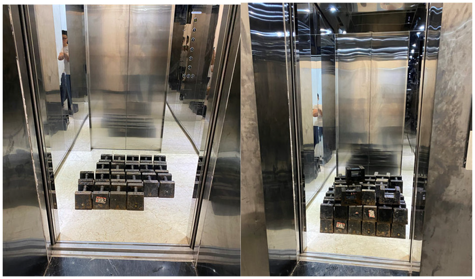
Different loading weights for the car (part of the loading process).
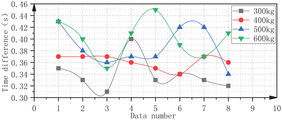
It can be seen from the test curve that after emergency braking, the car frame has damping and attenuation vibration, and its amplitude attenuates exponentially with time. During the operation of the car, the low-order vibration has a great influence on the ride comfort. In order to study the low-order vibration characteristics of the system and obtain the low-order vibration damping, the vibration curve obtained by the test is filtered with low-order filter. The vibration curve obtained after filtering is shown in Figure 9. It can be seen from the Figure 9 that with the increase of load, the period of small damping vibration increases gradually. The attenuation performance of vibration is usually described by logarithmic decrement rate (δ), which is the natural logarithm of two adjacent amplitude ratios in the same direction after a period. On the test curve, read the corresponding value and time of wave crest and trough, and then we can get the ratio of logarithm of two peaks or troughs in the upward (

Attenuation diagram of free vibration under four kinds of loads.
Upward time difference (s).

Upward logarithmic decrement rate.

It can be seen from the period average value in Table 4 that with the increase of the load mass in the car, the attenuation vibration period also increases, and the period value increases from 0.336 to 0.400 s. The variation trend of the upward time difference is shown in Figure 10. It can be seen from the Figure 10 that, the overall cycle change is relatively gentle, and it can be clearly seen that the period increases with the increase of the load mass in the car.

Upward time difference.
From the average value of logarithmic decrement rate in Table 5, it can be seen that with the increase of load mass in the car, the logarithmic decrement rate also increases, and the logarithmic decrement rate increases from 0.176 to 0.314, and the change trend of logarithmic decrement rate is shown in Figure 11.

Upward logarithmic decrement rate.
Analysis of downward test results
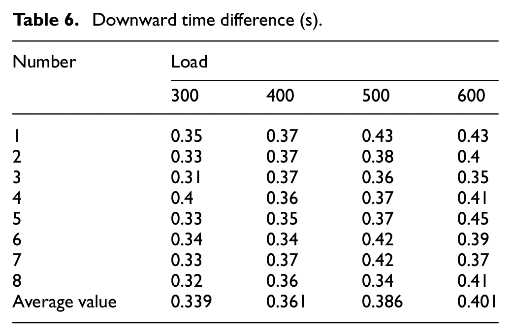
Referring to the upward process test method, the acceleration of the car frame with different weights during downward emergency braking can be obtained (Figure 12). The downward emergency braking acceleration curve is similar to the upward. Tables 6 and 7 show the calculation results of the time difference and logarithmic decrement rate of two adjacent peaks or troughs in the downward.
Downward time difference (s).
Downward logarithmic decrement rate.


Attenuation diagram of free vibration under four kinds of loads.
It can be seen from the period average value in Table 6 that with the increase of the load mass in the car, the attenuation vibration period also increases, and the period value increases from 0.339 to 0.401 s, and the change trend of downward time difference is shown in Figure 13. It can be seen from the Figure 13 that the period increases with the increase of the load mass in the car.
Downward time difference.
From the average value of logarithmic decrement rate in Table 7, it can be seen that with the increase of load mass in the car, the logarithmic decrement rate also increases, and the logarithmic decrement rate increases from 0.216 to 0.352, and the change trend of logarithmic decrement rate is shown in Figure 14. It can be seen from the figure that the logarithmic decrement rate changes greatly at 300 kg, while the logarithmic decrement rate changes gently under other loads. It can be clearly seen that the logarithmic decrement rate increases with the increase of the load mass in the car.

Downward logarithmic decrement rate.
Calculation of system vibration characteristic parameters
Analysis of experimental results
From Tables 4 and 6, the average period of attenuated vibration measured under different loads in upward and downward is drawn as shown in Figure 15. It can be seen that under the same load, the attenuation period of descending is slightly larger than that of upward, which is related to the emergency stop position of each group of tests. But under the same load, the average period difference is not large, and the change trend is the same, which shows that the emergency stop free vibration method has good repeatability and can be applied to the measurement of vibration characteristics of elevator traction system.
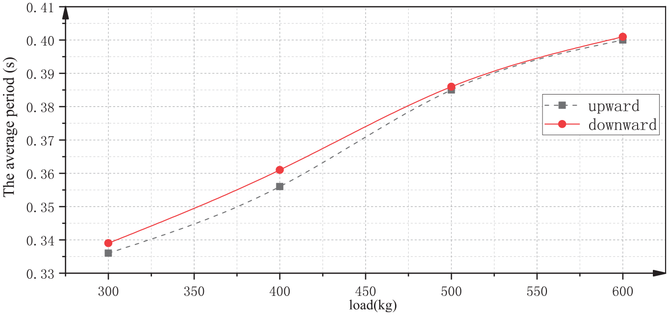
The average period of upward and downward damping vibration.
According to the damping test calculation method introduced in section 2, the free damping vibration period and logarithmic decrement rate under different loads obtained are analyzed, combined with the quality parameters of the elevator car itself, the system under different loads can be obtained natural frequency, stiffness, damping ratio, and damping of vibration.
According to the definition of natural frequency, the vibration stiffness of the system is as follows.

Where,
From equation (11), combining formula (13) and formula (14) the damping of the system can be obtained.

The above-mentioned periodic and logarithmic decrement rate values are substituted into the formula with average values. The damping ratio, natural frequency, stiffness, and damping values obtained are shown in Table 8.
Calculated values of system vibration parameters.

The relationship between the calculated parameter value and the load is plotted as shown in Figure 16. It can be seen from the figure that the natural frequency and stiffness of the system will decrease with the increase of the load in the car. The results obtained from the up and down direction are basically the same, which shows that the experimental scheme is feasible and the experimental results are highly reliable. At the same time, it also shows that the direction of the elevator car running before the emergency stop has an effect on the natural frequency and stiffness of the system. It can also be seen from the figure that the natural frequency and stiffness of the upward are slightly higher than those of the downward.

Variation of system vibration parameters with load.
In addition, it can be seen that as the load increases, the attenuation coefficient and damping of the system also increase. Except for the load of 400 kg, there is a certain difference between the results obtained from the upward and downward, indicating that the car running direction before the emergency stop has an impact on the attenuation coefficient and damping.
Comparative experiments
The other two elevators are tested with 200 and 400 kg loads. The calculation of vibration parameters is shown in Table 9. Because the traction ratio and wire rope parameters of the two elevators are different, the calculated natural vibration parameters of the system are different. However, it can still be seen from the calculation results that with the increase of the load mass, the natural frequency, and stiffness of the traction system gradually decrease, while the attenuation coefficient and damping gradually increase. The damping is related to the initial operation direction of the system, and the downward damping is greater than the upward damping.
Calculation of vibration parameters in supplementary test.

From the above analysis, it can be known that the experimental method used in this paper can quickly, efficiently, and conveniently obtain the variation laws of stiffness and damping of the elevator under different loads and different running directions, and can realize the research on the vibration characteristics of the overall elevator system, so as to provide reference for improving the comfort and safety of the elevator.
Conclusion
The basic parameters of the system are the direct reflection of the comprehensive performance of the elevator. Their analysis is of special significance because they define the quality basis for security and their maintenance in relatively heavy working conditions. Damping plays an import role in preventing the unstable vibration of the elevator system. The conclusions are as follows:
Due to certain limitations regarding the available measuring equipment and elevator safety protocols, it is difficult to test the running damping of elevator. By means of emergency braking to stimulate the traction system, the damping of a traction system can be tested efficiently and accurately under the condition of ensuring the safety of the equipment. According to the free vibration acceleration curve of the car, it can be seen that the car has small damping to attenuate vibration whether it is up or down.
The vibration of traction system is affected by many factors, which is a vibration problem with infinite degrees of freedom. For the car frame vibration problem, the low-order frequency is the main component, and the high-order frequency component can be ignored. Therefore, the basic model is possible to significantly simplify. The experiment also proves its accuracy and rationality.
In the elevator system, damping coefficient is not a constant value, just like the damping period is different depending on the loading mass of the car. In addition, the damping coefficient is also related to the initial running direction of the lift car. The damping in the downward direction will be slightly greater than that in the upward direction, even under the same position and speed.
Footnotes
Handling Editor: Chenhui Liang
Declaration of conflicting interests
The author(s) declared no potential conflicts of interest with respect to the research, authorship, and/or publication of this article.
Funding
The author(s) disclosed receipt of the following financial support for the research, authorship, and/or publication of this article: The work presented herein was conducted with the financial support of Natural Science Foundation of Guangdong Province (2021A1515012037).