
Abstract
The lubrication characteristics of a cylindrical gear transmission with a variable hyperbolic circular-arc-tooth-trace (VH-CATT) are important theoretical bases for the tribology design of the gear and its fatigue life prediction. Existing lubrication characteristics studies of it are based on simplified linear contact models, which are limited to one specific meshing position only. Therefore, the mathematical models for tooth contact analysis (TCA) and loaded tooth contact analysis (LTCA) are established to calculate most time-varying parameters in a meshing period, such as the kinematic parameters, spatial geometric parameters, and contact parameters, are calculated. Accordingly, a thermo-elastohydrodynamic lubrication (TEHL) model of an elliptical contact of this gear transmission is presented. Using all the proposed mathematical models, the TEHL results with smooth and rough tooth surfaces in a meshing period are analyzed. The obtained results reveal that these models can be used to predict the distribution of the film thickness, pressure, and temperature rise on the smooth and rough tooth surfaces of VH-CATT cylindrical gear transmission in each contact area of a meshing period. And it shows that the time-varying parameters have great influences on lubrication performance. Furthermore, the lubrication mechanism in a meshing period is investigated systematically in VH-CATT cylindrical gear transmission.
Introduction
VH-CATT cylindrical gear is a new type of gear developed based on the Gleason spiral bevel gear, as shown in Figure 1. Compared with traditional spur and helical gears, VH-CATT cylindrical gears have a strong bearing capacity, higher transmission efficiency, lower installation precision requirements, and no axial force.1,2 Because of its excellent performance, VH-CATT cylindrical gears have significant application prospects. In recent years, the exploration of VH-CATT cylindrical gear transmission progressed considerably. Tseng and Tsay 3 and Wu et al. 4 deduced the full tooth surface equation for VH-CATT cylindrical gears with transition tooth surface, and Zhao et al. 5 established an accurate three-dimensional mathematical model. Then, Wu et al. 6 studied the effect of machine tool errors on the tooth surface errors of this gear. Generally, poor lubrication is the main factor leading to frictional wear of gears. In a meshing period, most time-varying parameters, such as the gear geometry, speed, contact geometry, and load at each meshing moment, constantly vary. Concurrently, with the influences of pressure, temperature field, and tooth surface roughness in the lubricated contact area, the surface elastic deformation, lubricating oil viscosity and density will significantly change. Therefore, it is necessary to develop a TEHL model of VH-CATT cylindrical gears considering most time-varying parameters to study the lubricant behavior in the meshing process.

Model of VH-CATT cylindrical gear.
In 1916, for the first time, Martin 7 used a simplified model to apply the Reynolds equation for analyzing gear lubrication. With the maturity of gear technology and the elastohydrodynamic lubrication (EHL) theory as well as significant improvement in numerical algorithms and computer performance, the application to EHL theory has spanned a century and is still providing innovations. For instances, Xu and Kahraman 8 and Liu et al. 9 developed the EHL-line and TEHL-line contact model of a hypoid bevel gear and helical gear transmission, respectively. It should be noted that these studies mainly focused on theoretical conjugate tooth surfaces. In practical industrial applications, owing to the deviation caused by gear assembly and machining errors, elliptical contacts are formed on gear contact traces instead of theoretical line contacts. Therefore, a highly realistic elliptical contact was introduced into the EHL model of hypoid gears 10 and the applicability of this model was subsequently expanded to non-Newtonian fluid. 11 To achieve further closeness to a real scenario, the present study examines the lubrication mechanism of VH-CATT cylindrical gears with elliptical contact.
Following the determination of the effects of tooth surface roughness and thermal effect factor on gear lubrication performance, many scholars have progressively conducted EHL model studies with these on various gears. After Bobach et al. 12 introduced the roughness into the TEHL of an involute spur gear, Xue et al. 13 further considered load changes in the TEHL analysis of this gear. The lubrication performance of helical gears was studied by using a shear-thinning TEHL model incorporating ultimate shear stress. 14 For planetary gear, the model of EHL was established, which consider the effects of roughness. 15 After Pu et al. 16 established the EHL model considering roughness of a spiral bevel gear, Zhang et al. 17 predicted the coefficient of friction and tooth surface wear of this gear using TEHL technology. After establishing a TEHL model covering the full film, mixed, and boundary lubrication, Simon presented the methods to improve the lubrication performance of hypoid gear based on multi-objective optimization, 18 optimization of manufacture parameters, 19 and machine tool setting parameters. 20 Therefore, when analyzing the lubrication performances of VH-CATT cylindrical gears, the effects of the tooth surface roughness and the temperature rise cannot be ignored.
Most recently, numerous scholars have considered the time-varying parameters in the meshing process when analyzing the lubrication performance of gear transmission. For instance, the effect of load and speed were introduced into the TEHL model of a helical gear. 21 In addition, Wang et al. 22 presented a TEHL model of a spiral bevel gear, considering of the velocity vector and the surface roughness. Considering certain time-varying parameters along the meshing trace of a spiral bevel gear, the progressive mesh densification was introduced in the numerical calculation of a EHL model 23 and the behavior of dynamical wear, 24 friction, temperature, and contact fatigue 25 was subsequently discussed. Then, an EHL analysis of spiral bevel gears was conducted after considering the contact point migration due to the deformation under a load. 26 These studies serve as important references for the establishment of an accurate TEHL model of VH-CATT gear transmission.
The coupling of kinematic, spatial geometric, and contact parameters increases the complexity of lubrication analyses of VH-CATT cylindrical gears. However, existing studies on the EHL 27 and TEHL 28 of VH-CATT cylindrical gears are based on simplified linear contact models, which are limited to a specific meshing position. These studies ignore not only the time-varying parameters along the contact trace during gear meshing but also the tooth surface roughness. Therefore, this paper proposes a method for comprehensively calculating the time-varying parameters on a contact trace in a meshing cycle, which is developed using TCA and LTCA models. Subsequently, a TEHL model of VH-CATT cylindrical gears is established, and these time-varying parameters are extracted as the input parameters of the TEHL model. After the numerical calculation, the film thickness, pressure, and temperature rise distributions of a VH-CATT cylindrical gear pair under the effects of the time-varying parameters in a meshing period along the contact trace are analyzed in detail.
Contact analysis of VH-CATT cylindrical gears
To simulate the meshing of a gear pair under real working conditions, TCA and LTCA mathematical models based on the tooth surface equation of VH-CATT cylindrical gear transmission are established. The contact trace as well as time-varying parameters such as the main curvature, entrainment speed, slide-roll ratio, contact ellipse, load distribution, and maximum Hertzian contact pressure in the meshing process, obtained via TCA and LTCA in a meshing period are used as the input parameters for the TEHL model.
Tooth surface equation
VH-CATT cylindrical gears are machined using a double-edged milling cutter fixed on a rotating cutter head. The machining principle is shown in Figure 2.

Principle of rotating cutter-head milling.
The tooth surface equation 5 of the VH-CATT cylindrical gears is written as equation (1).
Where the upper (lower) symbols of ∓ and ± represent the convex (concave) tooth surface of the gears machined by the inner (outer) cutting edge; α is the pressure angle; θ is the cutter rotation angle, φ is the workpiece rotation angle; m is the gear module; R is the radius of the rotating cutter head (radius of the tooth trace), R1 is the pitch radius.

TCA model
As shown in Figure 3, the spatial coordinate system of the VH-CATT cylindrical gear pair is established based on the spatial configuration during meshing. ofxfyfzf is the fixed coordinate system; opxpypzp and ogxgygzg are the workpiece dynamic coordinate systems fixed with driving and driven gears, respectively; omxmymzm and onxnynzn are the intermediate coordinate systems in the coordinate transformation; l is the center distance; ϕp and ϕg are the meshing angles of the driving and driven gear, respectively.

Coordinate systems used for movement of driving and driven tooth surfaces.
It is assumed that Σp (the concave tooth surface) in opxpypzp represents the family of surfaces
Thus, the TCA mathematical model of the VH-CATT cylindrical gear pair in the meshing process is expressed as:
The transformation of Σp into ofxfyfzf is completed by:

Where
The transformation of Σg into ofxfyfzf is completed by

Where
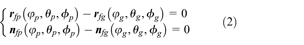
Based on the existence theorem of implicit function, 29 five independent equations with five unknown parameters are derived from equation (2), as follows:

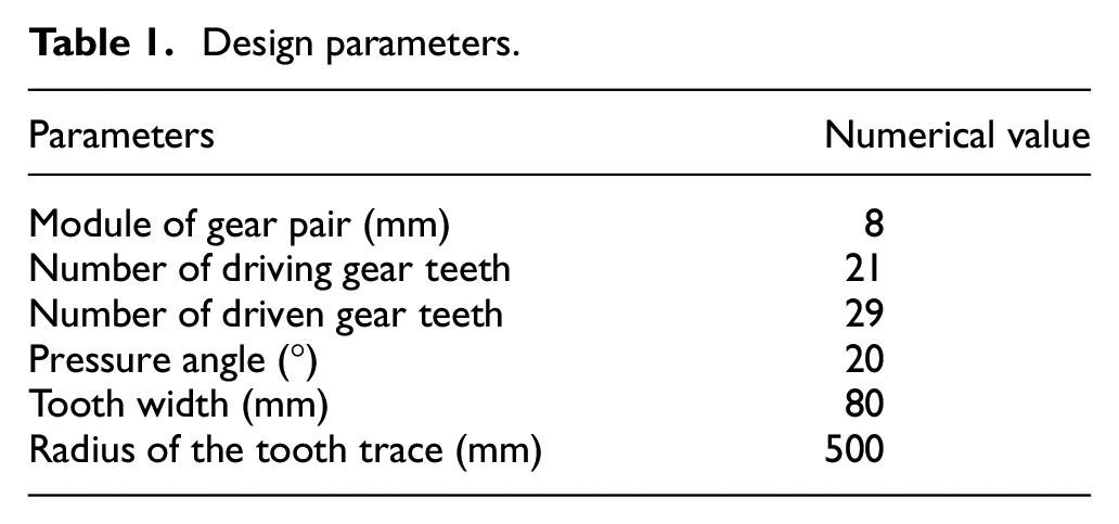
Taking the design parameters of the VH-CATT cylindrical gear pair listed in Table 1 as a case, all data reflecting the gear meshing status are solved through numerical iterations, the results as shown in Figure 4.
Design parameters.

Contact trace in (a) coordinate system opxpypzp and (b) coordinate system ogxgygzg.
The curvature of a VH-CATT cylindrical gear is an important spatial geometric parameter affecting its lubrication behavior. As shown in Figure 5, the principal orientations of Σp and Σg are

Curvature relationship of tooth surface.
Thus, the mathematical expression of the main curvature of the VH-CATT cylindrical gears can be derived as:

Where KiG is the Gaussian curvature and KiA is the average curvature of the tooth surface, which can be deduced by the surface theory. 30
Generally, velocity parameters have a major influence on the TEHL analysis of gear transmission. Therefore, the entrainment velocity,

Where
The sliding velocity,

The method for calculation

Where,
Thus, the calculation method of S is as follows:

LTCA model
Generally, the real working conditions of gear pair can be simulated using LTCA model. The LTCA model of the VH-CATT cylindrical gear transmission is established based on the method proposed in Klima et al. 31 and Jiang and Fang, 32 which is illustrated in Figure 6.

LTCA model of VH-CATT cylindrical gears.
In a meshing period, the VH-CATT cylindrical gear pair is in a contact state at a specific time, assuming that the contact load between Σp and Σg is distributed along the main direction of the Hertz contact ellipse. In Figure 6, the tooth curve is the intersection of the tooth surface and the normal plane along the relative main direction, ik (k = I, II) is a contact point, and jk (k = I, II) is a discrete point along the relative main direction. The gaps and contact loads of the contact points on each tooth surface in the meshing satisfy the following conditions:

Where
Thus, the maximum Hertzian contact pressure, ph, in the contact area can be deduced as follows:

Where a (or b) is the minor (or major) semi-axis of the Hertz contact ellipse.
The a and b are expressed as follows:

Where Ep and Eg are the elastic moduli of the gear material, μp and μg are Poisson’s ratios of the gear material, and αab, A, and βab are coefficients.
Basic equations of the TEHL model
Referring to the model proposed in Zhu, 33 the Reynolds equation of the VH-CATT cylindrical gear pair with an elliptical contact is as follows:

Where η is the viscosity of the lubricant, ρ is the density of the lubricant, h is the film thickness, p is the film pressure, and t is the meshing time.
Accordingly, the nondimensional Reynolds equation is

Where
Where η0 is the initial viscosity of the lubricant.
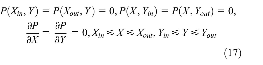
The boundary conditions of equation (15) are
To ensure that the TEHL model replicates a real scenario, the dynamic surface topography of the VH-CATT cylindrical gears is introduced into the film thickness equation in the form of the three-dimensional random roughness distribution. The film thickness equation is as follows:

Where h0 is the initial central film thickness; Rx and Ry are the equivalent radii of the curvature at the current meshing point in the directions of the tooth profile and tooth trace, respectively, which are derived from equation (6); x2/2Rx and y2/2Ry are the transient geometries before elastic deformation; δp and δg are the three-dimensional random roughness of Σp and Σg, respectively. δp and δg are not introduced into equation (18) for smooth tooth surfaces.
The local contact deformation, V, is calculated using the Boussinesq integral equation:
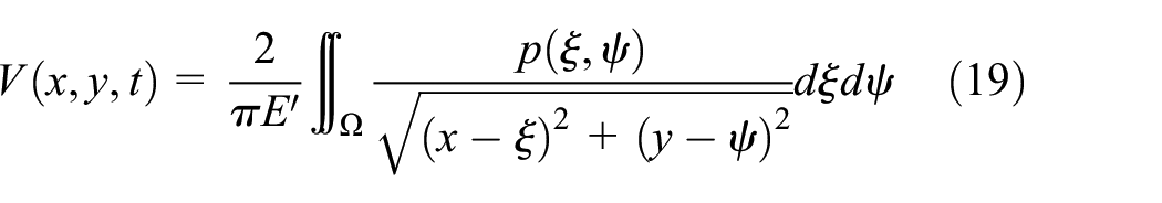
Where
Therefore, the nondimensional film thickness equation is:
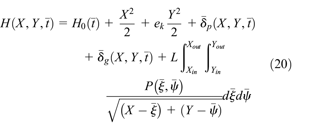
Where ek is the ellipticity, and ek = Rx/Ry. L is the contact deformation coefficient of the contact ellipse, and L = 3WRx/a2bE′.
Considering the influence of temperature change on the lubrication of VH-CATT cylindrical gears, the three-dimensional energy 34 is introduced into the TEHL model based on the theory of moving heat over a semi-infinite solid. The three-dimensional energy equation in the x, y, and z directions (z direction represents the film thickness direction) is as follows:

Where Ca and κ are the isobaric heat capacity and thermal conductivity of the lubricant, respectively, and u, v, and w are the flow rates along the x, y, and z directions, respectively.
To obtain the solution of the energy equation, the velocity field must be determined first. When the pressure distribution and the film thickness are known and the lubricant viscosity changes along the z direction, the flow velocities, u, v, and w, in the x, y, and z directions, respectively, are expressed as:

The fundamental equation for calculating the temperatures of the upper and lower tooth surfaces in the meshing is as follows:

Where T0 is the initial temperature, (ρp, ρg), (cp, cg), and (κp, κg) are the density, specific heat capacity, and thermal conductivity of the tooth surface material of Σp and Σg, respectively.
Viscosity is used as the dependent variable of pressure and temperature to reflect their relationship. The Roelands viscosity–pressure–temperature equation is used to calculate the viscosity:

Where Zη is the coefficient of the equation, Zη= α0/5.1(lnη0 + 9.67), and α0 is the viscosity-pressure coefficient.
The Dowson–Higginson density–pressure–temperature equation is selected to reflect the specific effects of pressure and temperature on density, and the equation is as follows:
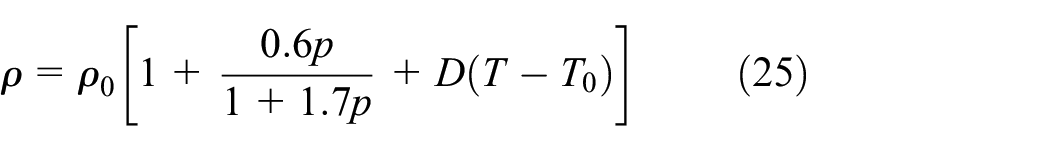
Where ρ0 and D are the thermal expansion rate and initial density of the lubricant, respectively.
The load is balanced by the integrating the pressure over the entire solution region. The load-balancing equation is

Numerical computation method
Figure 7 shows the program flow of above models. The Reynolds equation and the energy equation are discretized iteratively by combining the central and forward difference methods. The Jacobi bipolar iteration and the Gauss–Seidel iteration methods is used in high-pressure and low-pressure regions, respectively. To prevent divergence in the iteration process, the relaxation factor, c1, of the correcting pressure iteration is limited to 0.005–0.01, and the correction factor, c2, of initial central film thickness is limited to 0.001–0.01. The convergence precisions of the pressure and the temperature are

Calculation flowchart.

Three-dimensional rough surface profiles.
Model validation
In order to verify the present TEHL model of VH-CATT cylindrical gear transmission, the film thickness distribution solved by the present model is compared with the data solved by Wang et al. 22 and measured by Omasta et al. 35 To ensure that the conditions for validation are identical, the same input parameters, solving domain, and the computing grid are obtained via from Wang et al. 22 Table 2 and Figure 9 show that the central film thickness and film thickness distribution calculated by present model are substantially consistent with numerical simulation 22 and measured result 35 at same working condition. Thus, the TEHL model has a certain computational accuracy, and the error is small compared with the results in the literature.
Central film thickness comparison.


Results and analysis
Results of TCA and LTCA
The design parameters of the VH-CATT cylindrical gear pair used for the TCA and the LTCA are listed in Table 1. In addition, the input rotational speed, nin, of the driving gear is constant at 500 rpm, and the input torque of the driven gear is set as 232 Nm. The analysis results for the time-varying parameters along the contact trace in the VH-CATT cylindrical gears are generalized in Figure 10.

The (a) composite curvature radii along directions of tooth profile and tooth trace, (b) sliding velocities of driving gear (red line) and driven gear (blue line), (c) entrainment velocities, (d) slide-roll ratio, (e) gaps between contacting teeth, (f) load distributions and maximum Hertz contact pressures, and (g) contact ellipses on tooth surface.
As shown in Figure 10(a), Rx reaches a maximum near the pitch point and exhibits a parabola-like variation with the meshing process. In comparison, Ry gradually increases linearly with the meshing time. As shown in Figure 10(b), the |
Note that the rotation angle increment, Δϕ, of the gear is converted to the corresponding time increment, Δt, based on the input rotational speed, nin, that is, Δt = Δϕ/nin. In general, the meshing process of the studied gear pair alternately involves single or double teeth. Moreover, the values of some time-varying parameters between the single-tooth and double-teeth meshing areas rise and fall sharply. Therefore, a total of nine time nodes, ti (i = 1, 2, 3, …, 9), are selected as typical examples for the analysis of the lubrication characteristics in a meshing period as shown in Figure 10(f). Note that the entire gear meshing process is disaggregated into three stages, which are the first meshing stage (t1 − t3), the second meshing stage (t4 − t6), and the third meshing stage (t7 − t9), respectively.
Results of TEHL with smooth tooth surfaces
The time-varying parameters in Figure 10 and the lubrication parameters in Table 3 are taken as the input parameters of the TEHL model. Figures 11 to 13 give the numerical calculation results of the film thickness h, pressure p, and temperature rise, T, along the X- and Y-axes in a complete meshing period.
Material parameters of gear pair and lubricant.

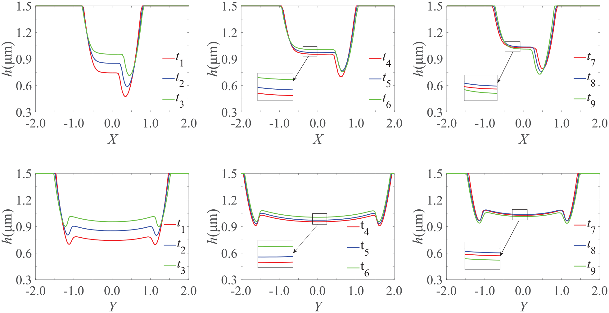
Film thickness distributions along X- and Y-axis directions of contact ellipse in meshing period.

Pressure distributions along X- and Y-axis directions of contact ellipse in meshing period.

Temperature rise distributions along X- and Y-axis direction of contact ellipse in meshing period.
h, p, and T, exhibit different variation trends in different meshing stages, as observed from Figures 11 to 13. The Rx, Ry, |
To evaluate the lubrication performance in the different meshing stages more intuitively, the contour lines of h, p, and T under smooth tooth surfaces are plotted in Figure 14.

The contours of (a) film thickness h, (b) pressure p, and (c) temperature rise T in meshing period.
Figure 14 shows the significant differences in h, p, and T at different meshing moments, which are caused by the variations in the time-varying parameters at each moment. Therefore, the positions of the minimum film thickness, maximum pressure, and maximum temperature rise deviate with the meshing time, and at each meshing instant, a prominent squeezing effect occurs along the flow direction (X-axis) of the lubricant. During different meshing stages, that is, when the VH-CATT cylindrical gear pair operates under the transmission condition of a single-tooth and double-teeth alternately carrying the load, the h, p, and T change abruptly in the calculation area. This is because of the rapid variations in the load and the contact ellipse in a short time.
Based on the TEHL results for the VH-CATT cylindrical gears considering smooth tooth surfaces, Figure 15 gives the variations in the minimum film thickness h-min, center film thickness h-cen, maximum pressure p-max, and maximum temperature rise T-max in a meshing period. Here, define λ as the increment in the TEHL results at the current moment compared with that in the previous one, that is, λ = 100(Cr − Pr)/Pr%, where Pr and Cr represent the TEHL values at the previous and current meshing moments, respectively.

The (a) minimum film thickness, (b) central film thickness (c) maximum pressure, and (d) maximum temperature rise.
First, Figure 15 shows that the lubrication condition is the least favorable at the instant when the gears initially mesh, when the occurrence of friction and wear failure are the most probable. The lubrication condition gradually improves as the meshing progresses. Second, because the time-varying parameters change significantly in Δ(t1 − t2), λ increases or decreases rapidly in this period. The first peak values (0.63 ms) of the four λ curves are 12.49%, 8.02%, −7.61%, and −7.10%, respectively. Concurrently, it is noted that the λ values clearly fluctuate at 3.74 and 5.71 ms caused by the switch between single-tooth and double-teeth load. Finally, when t is 4.62 ms, the gear pair is located near the pitch point, and S is 0 at this time. Thus, h-min,p-max, and T-max have good extreme values of obvious lubrication near the pitch point, which are 0.8036 μm, 0.6948 GPa, and 38.6125°C.
Results of TEHL with rough tooth surfaces
To predict the lubrication characteristics more accurately in a meshing period of a real machined surface, this section introduces the three-dimensional surface roughness based on the input parameters of smooth TEHL. The TEHL results considering rough tooth surfaces for the VH-CATT cylindrical gears are summarized in Figures 16 to 18.
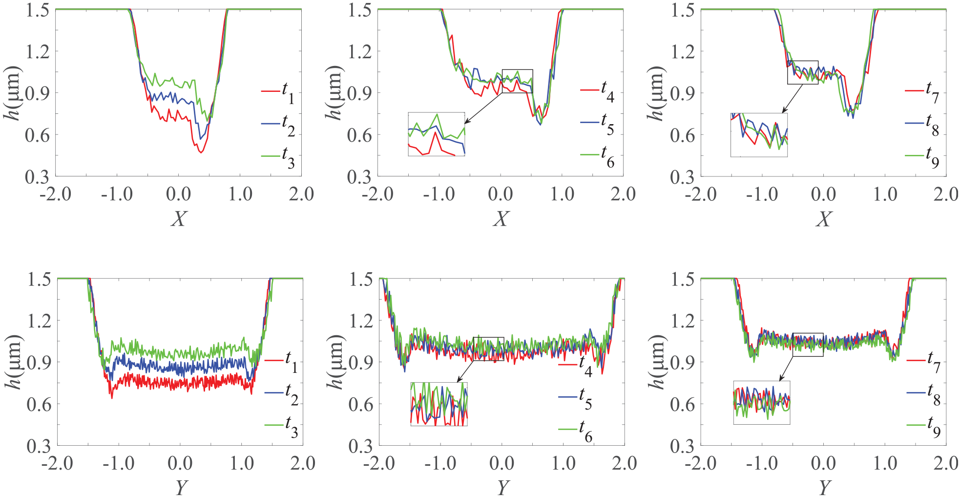
Film thickness distributions along X- and Y-axis directions of contact ellipse in meshing period.

Pressure distributions along X- and Y-axis directions of contact ellipse in meshing period.

Temperature rise distributions along X- and Y-axis directions of contact ellipse in meshing period.
Figures 16 to 18 show that the TEHL numerical simulation results for rough tooth surfaces are significantly different from those of smooth tooth surfaces, which are shown in Figures 11 to 13. Under the effect of roughness, although the variation laws of the TEHL results for smooth tooth surfaces still apply in each meshing stage for rough tooth surfaces, the latter exhibit clear oscillations. The temperature rise between the different meshing stages for rough tooth surfaces exhibits numerous divergent peaks, as seen in Figure 18. In a meshing period, the smaller film thickness and larger pressure are, the higher temperature is. Therefore, the first meshing stage is most likely subjected to the influence of direct contact of the rough peaks by comparing the peaks of temperature at different meshing stages.
To facilitate direct observation of the lubrication performance of the VH-CATT gear pair under thermal and roughness effects, Figure 19 presents contour maps.

The contours of (a) film thickness h, (b) pressure p, and (c) temperature rise T in meshing period.
In Figure 19(a), the squeezing effect caused by the extrusion of lubrication at each meshing instant is still evident; however, the shape of the film fluctuates owing to the roughness of the gear surface. The pressure in Figure 19(b) exhibits abrupt changes between different meshing stages. A large ratio of the contact load to the contact ellipse implies a high viscosity of lubrication and a strong influence of the roughness on the pressure. In Figure 19(c), the influence of roughness on the lubrication performance of the VH-CATT cylindrical gears can be manifested by the number of dark red spots in the contact ellipse. Note that the there are some dark red spots randomly distributed on the right side of the contact ellipse at t8 and t9 in red rectangular box of Figure 19(c). The reasons for this phenomenon are the random distribution of roughness and the poor lubrication performance in t7 − t9, so it is still possible to damage the oil film by the roughness of the tooth surface.
Conclusions
In this study, the TEHL model of VH-CATT cylindrical gear transmission in elliptical contact has been established by considering the effects of time-varying parameters. The numerical method for calculating the time-varying parameters of this gear transmission in a meshing period has been proposed. After introducing the time-varying parameters in a meshing period, the lubrication characteristics considering smooth and rough tooth surfaces have been investigated. Based on numerical simulation, the following conclusions can be drawn:
The kinematic parameters, spatial geometric parameters, and contact parameters of VH-CATT cylindrical gear transmission constantly vary in a meshing period. To obtain these time-varying parameters, the TCA and LTCA models are established. Considering the effects of temperature and time-varying parameters for the analysis of the lubrication characteristics, a TEHL model of the VH-CATT cylindrical gears in elliptical contact is presented.
The TEHL results for smooth tooth surfaces show that the lubrication characteristics of the VH-CATT cylindrical gears are directly affected by time-varying parameters. The lubrication characteristics in the entire meshing process fluctuate because the load distribution and Hertz contact ellipse vary significantly. The lubrication performance at the beginning of the first meshing stage—when the film thickness is the smallest, the pressure is the largest, and the temperature rise is highest—is the worst. However, the performance improves rapidly as the meshing progresses. The second meshing stage presents the best lubrication performance. The lubrication performance of the third meshing stage is better than that of the first meshing stage and inferior to that of the second meshing stage.
The TEHL results for rough tooth surfaces show that the lubrication characteristics obtained after considering roughness are closer to the actual lubrication characteristics. The overall trends of the variations in the lubrication performance in a meshing period for rough tooth surfaces are similar to those observed for smooth tooth surfaces. However, the positions of the minimum film thickness, maximum pressure, and maximum temperature rise shift are more stochastic than the corresponding positions for smooth tooth surfaces. The stage most likely subjected to the influence of direct contact due to rough peaks is the first meshing stage, followed by the third meshing stage.
Footnotes
Appendix
Handling Editor: Chenhui Liang
Declaration of conflicting interests
The author(s) declared no potential conflicts of interest with respect to the research, authorship, and/or publication of this article.
Funding
The author(s) disclosed receipt of the following financial support for the research, authorship, and/or publication of this article: The present study was founded by the National Natural Science Foundation of China Project Nos. 51375320 and 51875370, the Foundation of the State Key Laboratory of Mechanical Transmission of Chongqing University Project No. SKLMT-KFKT-201807, and the Natural Science Foundation of Gansu Province Project No. 18JR3RA140.