
Abstract
Woven composite reinforcements usually have very specific and high performances. However, the weaving process may be aggressive and damage warp tows, due to the flexion and friction sensitivity of the used materials, for example, carbon and glass. This is a crucial point as damages, which consist of filament breakages, material loss or bonding errors, tend to cause a loss of mechanical properties and/or a bad visual aspect. Stages from tensioning to reed were quite widely studied and optimised. Nevertheless, recently since density is high the impact of yarn-to-yarn and yarn to heddle wires friction at the shedding step have been clearly established. The weaving devices used are a loom specifically adapted to interlock weaving and a UNIVAL 100 Jacquard shedding system. A UNIVAL Jacquard from Stäubli, which is a motorised technology, enables any shed geometry and individual yarn motion thanks to special parameters. Such yarn movements, which are hardly reproducible with standard shedding devices, may help towards a better understanding of yarn interactions and wear mechanisms inside the shed. To understand the damage phenomenon and to reduce it, a methodology would consist in counting damage events which occur on yarns and hamper a correct shedding according to time. Several yarn interactions were set up in order to understand the effect of shedding parameter configuration on yarn damage generation. The results clearly show the several damage evolutions in time are different according to shedding configurations and that some configurations can help to reduce warp yarn damages for high-density multilayer weaving. In addition, an algorithm for weave pattern reading and processing has also been set up to manage automatically shed geometry and tow density in the shed.
Introduction
The use of composites materials reinforced with technical materials is becoming common in a variety of structural applications in aeronautic, automobile, aerospace or construction field.1 –5 Industrials found in composites a lightweight but performant solution that are known for having a higher specific strength and specific stiffness than some metals. 6 Composites are intrinsically inhomogeneous and often anisotropic, and recent studies, motivated by the variety in use and in composition of composites, proposed several model to predict the mechanical properties of composites based on machine learning tools.7,8 This testifies the importance of generating composites and reinforcements for composites with a well-controlled process.
Nevertheless, high-density weaving for composite reinforcements usually causes troubles due to the current use of sensitive materials, like carbon, glass, ceramic or high-performance synthetic materials. 9 The main interest in the use of 3D woven structures is the possibility of weaving technical fibres to form massive one-piece woven structures designed to fit mechanical solicitations, 10 with high resistance to delamination thanks to their binding warp yarns.11,12 According to the standard classification of interlock woven fabrics, 13 stuffer or inter-ply warp yarns face few yarn-to-yarn interactions whereas binding yarns are more subject to yarn-to-yarn friction while shedding. The repetition of yarn-to-yarn or yarn-to-loom friction due to shedding progressively causes damage to warp yarns during weaving by breaking and removing fibres or filaments.14 –16 Yarns may be progressively worn, which reduces the final resistance of the composite.14,17,18 Recent studies have observed such phenomena at the weaving process stage in a general and visual way showing different behaviours depending on the material: (i) for glass material, broken fibres and debris accumulating over and around the loom have been observed 15 ; debris have a small length (under 0.5 mm) and fibre breakage does not occur to a large amount; (ii) for carbon, fibres are protruding from the material 19 ; (iii) for synthetic material, short fibres and long debris have been observed, 13 because polyester can be bent at room temperature due to its ductile characteristics,18,20 therefore it can stand higher curvature. 9 It may be noticed in Figure 1: (a) free filaments ends, (b) free filaments entangled with yarns, (c) bigger clusters composed of filaments and kept linked to warp yarns.

Damages on warp yarns due to shedding.
Damages seem to originate from friction between yarns and loom parts.14,15,19,21 A particular attention is paid to modifications needed for the loom to reduce rubbing of yarns against machinery 14 which is a major cause of damages. A significant amount of fibre damage would happen in the tensioning 22 and back shed regions but also in the reed region because of the accumulation of damages and the action of reed dents. 19
On the opposite, Mc Hugh 23 does not notice an evident “filamentation,” that is, filaments separation from yarn and breakages, between the warp creel and the rear of the harness. The main degradation process would be a product of shedding, depending in particular of the nature of the weave structure and heddle action. For that matter, one of his purposes is to use the shedding parameters configurations of a motorised Jacquard so that movement may be more continuous and abrasion may be reduced.
Decrette et al. found similar results using shed phase and close shed profile UNIVAL motorised technology, with an increase of counted damages for higher shed motion profiles, whereas using a more sinusoidal profile a higher close shed profile value tends to reduce induced damages. 20
Some recent studies have focussed on damages and friction phenomena at the shedding stage, using sensors to monitor the weaving process, or simulating ex-situ yarn-to-yarn friction on a specifically designed device at the lab scale.20,24,25 Those damages were also observed during the carbon braiding process, 26 for which a loss of tenacity up to 27% was observed by Calba et al. due to yarn-to-yarn friction.27,28
Bessette’s observations on glass yarn weaving, 29 thanks to a tension sensor measuring warp tension on a specific warp yarn, pointed to an increase in warp yarn tension:
– as the monitored warp yarn is in motion compared to the case where the monitored yarn is motionless whereas neighbouring yarns are moving,
– as warp yarns are crossing during shedding,
– for raising warp yarns compared to lowering warp yarns,
It was also observed an increase of tension according to time, due to the accumulation and increase of damages during the successive weaving cycles.
Walther et al. specifically focussed on yarn-to-yarn friction by isolating and mimicking yarn-to-yarn interactions thanks to an experimental weaving simulation tribometer. 25 It was shown that normal forces are clearly increasing as the contact area between the two yarns increases. Even if untwisted yarns, generally used in composite reinforcement, have a better reorganisation ability, they have the highest tangential forces during yarn contact because of entanglement.
Even if it is commonly observed, for brittle materials, that damages appear since warp creel and increase up to the harness, 17 some authors agreed that shedding is a major issue.20,24 Actually, from a quiet evolution, damages greatly increased since the beginning of the harness for different reasons: (i) the accumulation of damages, (ii) the angle formed by filaments because of heddles while the shed is opened, (iii) the large number of picks while a section of the yarn has to go through the harness and (iv) the high density making the yarn rubbing against each other.
Walther et al. investigated several situations of yarn-to-yarn interactions within the shed, thanks to a tension-monitored warp yarn. 24 Similar tension peaks are noticed for all cases where the studied yarn is interacting with neighbouring yarns, that is, (i) when it needs to get extracted from static neighbouring yarns at motion beginning, (ii) when it crosses one or several moving neighbouring yarns and (iii) when is the studied yarn remains static but on the top of the mass of moving yarns.
In conclusion, the friction due to yarn-to-yarn interaction is significant in weaving process damages with shed geometry, relative position of yarns into the mass before motion, and static aspects of friction are at least as critical as crossings during shedding. The different aspects of friction nature (static or dynamic) during weaving have yet not been investigated.
An interesting aspect with less sensitive materials like polyester, is that damages seem to appear mainly in the shed region. 20 Therefore, yarn-to-yarn friction of polyester and its behaviour is the object of some recent studies30,31 which presented impacting degradation parameters: yarn tension, heat, abrasion frequency; and linked can be made between those experimental result and weaving conditions, especially the shedding stage due to yarns movements. Then, polyester is chosen for this study as damages before harness are avoided, friction happening during shedding can be more specifically targeted.
Concerning the shedding damages generation, only few studies can still be noticed, perhaps because of difficulties in of changing the parameters of shedding motion, as it needs very specific equipment. This is why we have chosen to focus on this particular stage. Such a study will need to set up a design of experiments which will help to emphasise the effect of shedding and its parameters on the weaving quality and specifically on warp damages.
Materials and methods
Material and weaving conditions
512 polyethylene terephthalate (PET) untwisted multifilaments with a fineness of 170 tex are used for the production of a multilayer fabric. The warp is organised with 8 warp layers with a reeding of 16 yarns per dent. The harness is composed of 32 columns of 16 Jacquard strings. The basic pattern in Figure 2 was designed to generate eight yarn interactions for each pick in each reed dent.
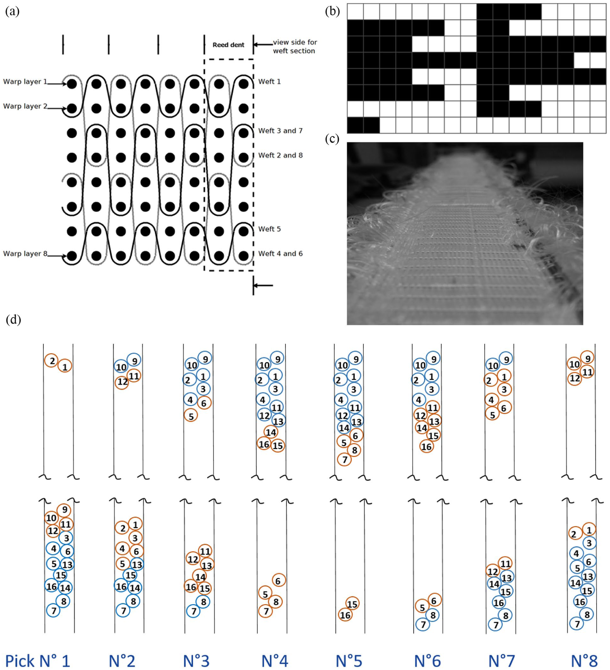
Height-layers weaving pattern and associated fabric: (a) fabric warp cross-section, (b) weave pattern corresponding to cross section, (a and c) resulting woven fabric, and (d) warp cross-section at reed stage for each pattern pick: at next shedding, moving yarns marked in orange, static yarns marked in blue.
A high warp density of 85 ends/cm (14.5 ktex/cm) was set on the loom, leaving small space in reed dents for yarns crossing and yarns positioning at bottom and top positions at opened shed stage. A major issue of our pattern design was the generation of specific, limited and chosen yarn-to-yarn interactions in order to have an easier comprehension of interaction phenomena. In this case, as shown in Figure 2(d) and thanks to the weave pattern, moving yarns are always at the nearest altitude from shed crossing plane. It results in the generation of only “crossing” interactions (moving yarns interacting on shed crossing plane during shedding) and “post-motion” interactions (moving yarn reaching static yarns at their motion ending). As a clarification work on understanding UNIVAL parameters impacts, the chosen pattern seems to be an easy way for a constant yarn-to-yarn interactions generation. The chosen material enables a clearer observation and classification of defects as it is not subject to filaments fragmentation like glass or carbon.
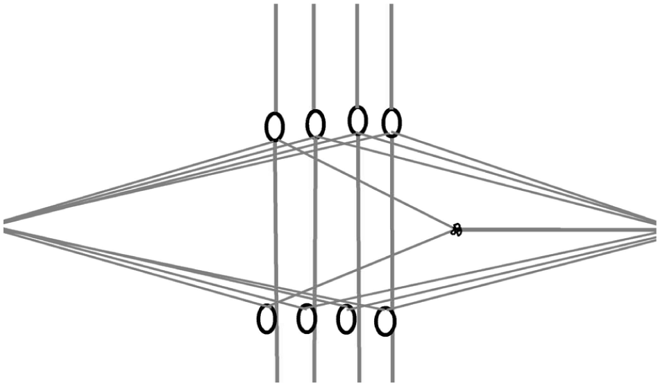
The devices, sketched in Figure 3, used are a motorised Jacquard shedding system and a multi-layer rapier weaving machine consisting of the following specifications:
– displacement according to the Z axis to keep the rapier levelled with the shed,
– linear take-off because of fabric depth,
– step-by-step weaving cycle (weft insertion, warp cutting, beat-up + shedding + take-up).

Illustration of weaving devices and warp geometry.
In the weaving cycle, yarn motion during shedding lasts 200 ms.
Shed geometry and parameters
The basis shed geometry set in this investigation is a clear shed. As described in Figure 4, front shed amplitude (

Basic clear shed geometry.
The shedding system is a UNIVAL 100 motorised Jacquard from Faverges, where stepper-motors replace traditional mechanical hooks for Jacquard string driving. A motorised technology offers more flexibility for UNIVAL – called profiles – movement kinematics and shed geometry (which is fixed with traditional Jacquard). 32 Other available parameters are close shed profile (yarns which should stay on the same positions for several picks are moving near the shed centre and coming back) and phase difference (setting a delay or a lead on movement beginning). The phase difference can be set continuously all over the yarns or over groups of yarns.
Shed profile and close shed profile effects were briefly studied previously. 20 Therefore, this paper focuses on shed geometry and phase difference.
One major interest of UNIVAL Jacquard, in addition to the motorisation of each yarn, is the gathering of the totality of very specific parameters associated to traditional mechanical shed motion systems. For instance shed geometry and geometry offset is in obvious correspondence to clamping loop setting on lever in frame weaving.
Geometry Offset consists in setting a regular amplitude offset all over yarn or in portions of the shed. Example in Figure 5 shows the setting chosen in this investigation, that is, a 1 or 10 mm offset for 1 yarn over 2 all over the shed. Figure 5(a) exhibits a continuous line which is the basic yarns position and a dotted line corresponding to the offset position for concerned yarns. In case of weft floats, this may present a crenellated aspect (Figure 5(b)). Offset value have been chosen as the smallest value available after 0 (offset = 1 mm) in the first case, and for the second the value is the eyelet height, that is to say a sufficient offset to prevent any static contact between neighbouring eyelets associated yarns.
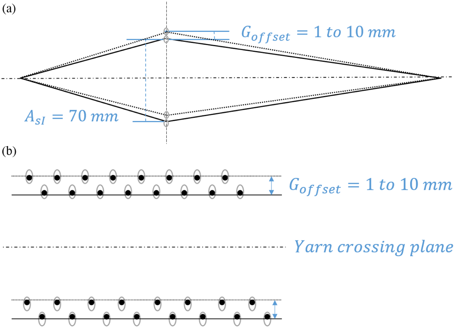
Impact of geometry offset UNIVAL parameter on a clear shed basis geometry: (a) side view of the shed at open shed stage and (b) cross-section of warp yarns at open shed stage (weaver side).
Shed phase difference here corresponds to virtual tagger indexes which are used for cams motion indexing. The UNIVAL parameter setting here is to be considered at the yarn scale instead of frame scale in cam motions.
Shed phase difference is the setting of a delay or an early departure of yarns all over the shed or for parts of the shed only. Phase difference can be homogeneous for groups of yarns (for instance yarn for 1 to i can leave at 0° and yarn from i + 1 to n can leave at 30°). It can also, as shown in Figure 6 change to a phase value to another linearly, enabling a progressive starting motion of yarns: at

Illustration of phase difference parameter on yarn position evolution, for a given shed profile, according to time at shed motion beginning.
Phase difference range is −45° (early start) to +45° (delayed start). Here a (0°; +45°) range with a linear evolution from yarn N°1 (0°) to yarn N°512 (+45°) has been chosen. This range is sufficiently wide for an easy visual observation.
Design of experiments
A design of experiments (DOE) was chosen with two levels per parameter to make a preliminary description of shed geometry and phase difference behaviour. As described in Table 1, two levels have been chosen for each studied parameter, which generates four experiments.
UNIVAL parameters used and their DOE levels for each experiment.

In the present case, phase differences have been set to make a 5° or 45° global progressive and continuous starting delay between the first and the last Jacquard string. An offset has been set over a clear shed geometry, where odd strings are 1 or 10 mm higher than even strings.
Defects description
As described in the introduction section, several events may occur on PET multifilament yarns: monofilament breakage, bonding errors, fibre clusters, etc. Events generally belong to one of the cases defined according to observations. They are described in Figures 7 to 12. As an event is detected, the weaving process is stopped and following a visual inspection and analysis, the event is classified according to the six categories described in Figures 7 to 12 and removed before weaving resumption. As the UNIVAL Jacquard has a motor for each yarn motion, Jacquard string tension and difference between yarn target and real position is measured during shedding. Over tension of yarn and position error may sometimes be detected, which is noted “U 100 detected” in Table 2.

Filament cluster behind heald.
Filament cluster ahead of heald.

Free filament linking yarn and heald.

Inaccurate position of yarn because of free filament.

Floating yarn because of density.

Inaccurate position because of density and string tubes.
General results – events in % over total and total per experiment.
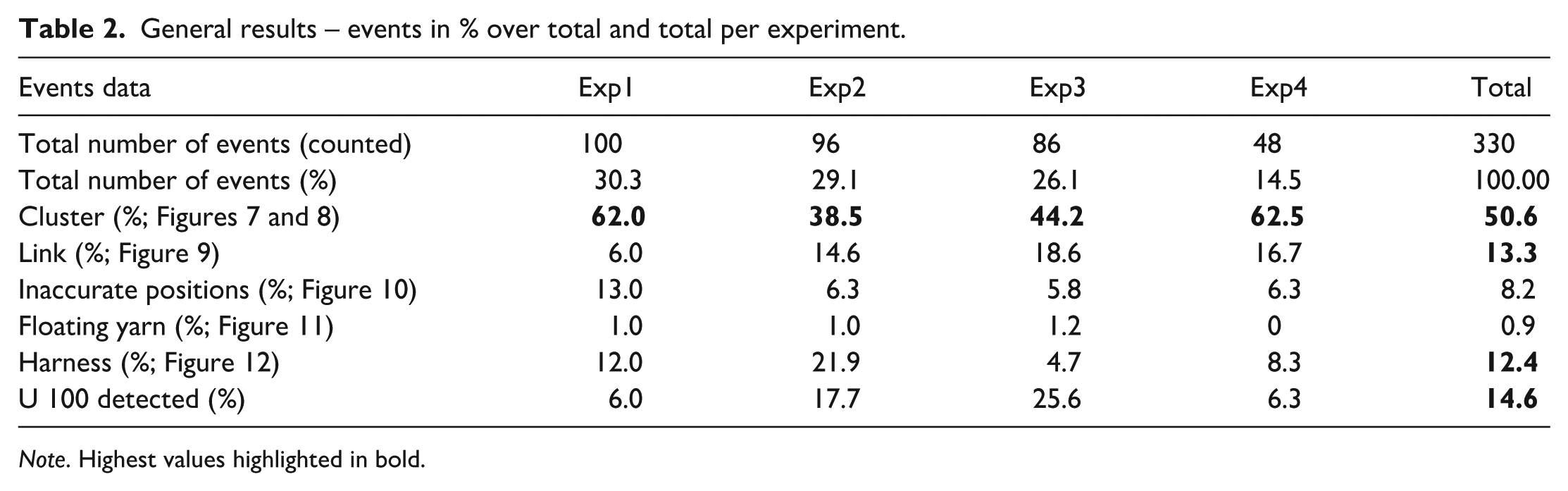
Note. Highest values highlighted in bold.
Data analysis
As explained previously, events, that is, defects our counted classified according to time into the described categories. The great observed regularity of events occurrence enables to point out linear tendencies of cumulative events, as it will be described in the results part. For categories having such tendencies, standard DOE tools are used to compare UNIVAL parameters weight, that is, impact on defect occurrences. 33
Results or answer of experiments are linked to factors by the general formulation in equation (1):

General formula of experiments results
which may be approximated by a Taylor-Mac Laurin DL in equation (2):

General formula approximation

As each experiment may be expressed with equation (2), a sufficient number of experiments enable solving the system and calculate coefficients
Parameters influence and relevance are also determined thanks an analysis of variance (ANOVA).
ANOVA aim is the dissociation of data variation attributable to studied parameters from global data variation. After the calculation of global and each parameters variance, Fischer-Snedecor-like random variables are built as the ratio of a given parameter variance over the global variance. Ratio proportion (here in %) of a parameter is an indicator of the part of data variation induced by the parameter level change, that is, a rough indicator of the parameter impact on the results.
Results
Weaving damage events which are observed during weaving w are classified and summed according to the pick number in one of the categories. General results are shown in Table 2 and Figure 13. Each specific event datum is expressed as a percentage of the global amount of events counted over one experiment. The last column shows each total specific event events counted over the four experiments, in percentage, over the total events.

Graph of general results. Events are classified according to categories for all experiments.
Filament clusters joining two yarns are predominant over the four experiments, representing 40%–60% of events in each experiment. Secondary cases are Jacquard strings linked by one or several broken free filaments, harness problems and UNIVAL over tension detections as any of them are over 10% of total events. Focus is made on the previous four cases (bold in Table 2). In comparison, other cases may not be considered as significant.
For a more accurate study of the significant cases, cumulative events are presented according to pick number. General trends of the effect of shedding parameters on weaving quality can be observed.
Figure 14 shows the cumulative events of all cases according to the pick number for the chosen shed geometry and phase difference parameters configurations. As events appear regularly, curves look quite linear and trends (number of event/pick) can be brought out. The importance of the influence of each parameter is shown in Table 3.

Global events counted for each experiment.
ANOVA: respective importance of phase difference and geometry offset parameters on total events.
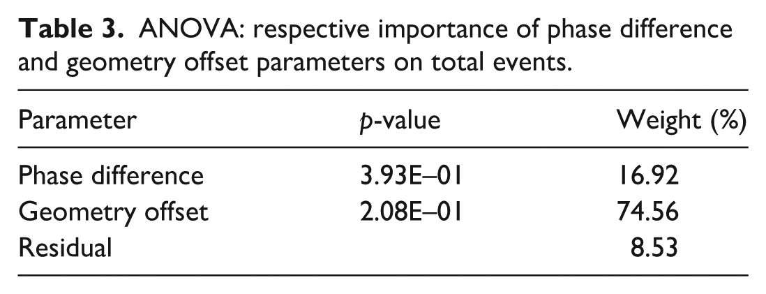
According to Table 3, geometry offset – all events taken into account – tends to have a major influence. In Figure 14, the two lower evolutions (exp 3 and 4) have a high offset level. Geometry offset’s main effect may be yarn starting movement simplification, as yarns density is halved.
Due to harness density, heat-shrinkable tubes used to protect Jacquard healds sometimes get blocked by neighbours and hampers a correct yarn position. Without offset, tubes form a dense layer difficult to cross. That can explain partly the amount of global events.
ANOVA first observations are confirmed in Figure 15 for geometry offset which has the highest coefficient value. Moreover

UNIVAL phase difference and geometry offset parameters coefficient values (
Figure 16 depicts cumulative filament clusters which have been observed during weaving. Even if linearity is not so obvious, global trends could be identified. According to Table 4, the influence of the offset parameter is as high as in the general results as the filaments cluster category represents half of total events. Here also damages are reduced with geometry offset (Figure 17).

Filament cluster counted for each experiment.
Respective importance of phase difference and geometry offset parameters on filaments cluster results.


UNIVAL phase difference and geometry offset parameters coefficient values (
Finally, this trend is confirmed in Figure 18 where fewer free filaments causing an inaccurate position are observed for a high level of geometry offset.

Yarn inaccurate position counted for each experiment.
As filaments clusters events represent more than 50% of defects (Table 2 and Figure 13), a fine study of coefficients seems also essential. The same conclusions may be hold here, with a higher and negative value of geometry offset
Phase difference effect seems globally more difficult to understand according to results in Figure 19,which presents the events detected with the help of UNIVAL 100 Jacquard (U 100), enlighten the influence of the phase difference: the lowest detections are observed with a low level of phase difference.

U 100 detected events counted for each experiment.
Discussion
A previous paper studied the two other UNIVAL parameters, that is, shed profile and close shed profile, 20 with the geometry offset and phase difference set to zero.
Figure 20 shows Decrette et al. results 20 with no phase difference and no geometry offset but the same shed profile and same close shed profile than the present study (Table 5).

Influence of shed profile and close shed profile parameters. Geometry offset and phase difference are set to 0.
Comparison of parameters level for Decrette et al. publication 20 and present investigation.

Note. Common parameters and highlighted in bold.
The results previously obtained in Decrette et al. were: (i) trends 1 and 2 (CSP 10%), corresponding to exp 1 and 2, are globally higher (0.081–0.1 event/pick), than trends 3 and 4 (0.03 and 0.06 events/pick); (ii) trends 1 and 3 (SP6) are also higher (0.1 and 0.06) tend to be higher than trends 2 and 4 (0.08 and 0.036). As conclusion was the positive impact of closed shed profile parameter on the weaving process, as well as a more sinusoidal-like shed profile.
By comparison with the present investigation, Decrette et al. events trends are tremendously higher than those found presently (0.02–0.04) with a geometry offset and phase difference parameter use. Both phase difference and geometry offset seem to have a positive and stronger impact on damage reduction, even with very low levels (respectively 5° and 1 mm), than shed and close shed profiles. As no phase difference was used by Decrette et al. in 2019, it may be conclude that phase difference do help reducing defects, but should be used for small values setting. As a matter of fact a high value of phase difference, instead of reducing local yarn density, may generate locally high amounts of friction between moving yarns.
Conclusion
This study shows yarn interactions during the weaving process are critical for multilayer fabrics. A methodology is proposed and adapted to identify and count events in the long term. Yarn damages needed to be described according to distinct categories corresponding to different observations and phenomena.
Damages may become very important and cause great damage to yarns because of bad parameter configurations. It becomes crucial in such cases to reduce it by using the right configuration. This preliminary investigation focussed on the shed phase difference and geometry offset. It was observed that their effects were significantly perceptible. From this study, an interesting configuration is emphasised, that is, a significant level of geometry offset combined to phase difference even if a lower level might be preferable. Phase difference trends and effects are not obvious and need to be more enlightened. Geometry seems to be a major parameter as density is decreased at shedding beginning.
The results which have been obtained require this study to be carried on especially with the geometry parameter.
Yet focussing on a material chosen for its easy defects observation and classification, the results can be considered as globally relevant for untwisted synthetic materials. Other materials, with dissimilar behaviour regarding to friction, will need to be used, in particular carbon or glass. A specific weave pattern was used but other patterns will also need to be designed for other specific yarn-to-yarn interactions generation.
Footnotes
Funding
The authors disclosed receipt of the following financial support for the research, authorship, and/or publication of this article: Authors acknowledge the French National Research Agency (ANR) for funding their work as part of ANR-19-CE10-0006 PREDICTISS -3D.
Declaration of conflicting interests
The authors declared no potential conflicts of interest with respect to the research, authorship, and/or publication of this article.