
Abstract
The contribution of Recycled Steel Wires (RSW) to the shear strength and behavior of pultruded glass fiber reinforced polymer (P-GFRP) hybrid composite beams with reinforced concrete infill, denoted as P-GFRP beams, was investigated experimentally and analytically in the current study. A total of six specimens with varying RSW ratio and stirrup spacing of the reinforced concrete (RC) core and a fixed shear span-to-beam depth ratio were tested to failure. The addition of RSW to concrete was established to have greater contribution to the beam strength with increasing stirrup spacing, that is, decreasing transverse reinforcement ratio. The contribution of RSW to energy dissipation capacity was found to be more pronounced in the elastic range of beam response as compared to the inelastic range. The theoretical calculations indicated that the RC core prevented the P-GFRP encasement from complete failure due to shear-induced material rupture at the initial stages of loading. By maintaining their integrity, the reinforced concrete-filled box beams (RCFB) were able to resist loading until complete failure associated with flexure-induced material rupture and web compression buckling. A strut-and-tie model providing accurate strength estimates for P-GFRP beams was also proposed.
Introduction
Effective material reuse has become very crucial as the earth’s resources are constantly depleting and the human population is growing quickly. Concrete trash makes up the majority of building waste in industrialized nations, with the European Union producing 150 million tons of it each year. In 2003, it was estimated that the United States produced 170 million tons of garbage.1,2 The utilization of material recovered from waste tires has emerged as the most environmentally friendly method for making investments in waste tire recycling financially viable following the introduction of numerous European Union laws. For both structural and non-structural uses, recycled steel wires (RSW), which are obtained from the tire recycling industry, can be a highly efficient concrete reinforcement material. The ability of RSW in Reinforced Concrete (RSWRC) to enhance the performance of the structures has been studied over the past three decades.3–5
Steel wires improve post-cracking strength and post-peak behavior in addition to strength and ductility, which are the concrete element’s most significant benefits from their addition. 6 Steel wires also produce a bridging mechanism on the fracture surfaces, increasing the concrete’s tensile strength. 7 In this method, the building element’s crack widths and displacement values under the same load drop while its energy absorption capacity, bending stiffness, and ductility all rise. The major drawbacks of concrete are its fragility and poor tensile strength. Small quantities of short fibers are added at random to a cementitious matrix to create a glass fiber-reinforced cementitious (GFRC) composite.
It possesses qualities like toughness, deformation capacity, splitting tensile, splitting compression, splitting, bending, shearing, impact resistance, fatigue resistance, and abrasion resistance. The literature has a number of experimental research that investigate the mechanical properties of concrete consisted of recycled fibers.8–10 According to the literature on the issue, RSF reinforcement can make cement-based materials much less brittle by increasing their toughness and post-cracking resistance. The RSW mechanisms (can be thought of as steel fiber) that span fracture surfaces in the concrete give crack opening restriction, which significantly boosts the ability of concrete buildings, particularly concrete structures, to transport loads and absorb energy. The RSW’s ability to redistribute strain allows for a far larger ultimate load than the breaking load.11,12 The characteristics of RSWRC have been studied and Mohammadi et al. 13 has observed increased tensile strength. Studies on the mechanical characteristics of FRCC were undertaken by Wang et al. 14 utilizing recycled fibers. They stated that a higher dose may be required to get the same effect, concrete that has recovered industrial fibers added to it may have mechanical properties that are close to those of conventional reinforced concretes. The flexural characteristics of RSWRC were assessed by Neocleous et al. 15 They claimed that recycled steel fibers from used tires significantly enhanced fiber reinforced concrete postpeak behavior. The characteristics of used fibers of various lengths in concrete were studied by Meddah and Bencheikh. 16 They claim that adding waste fibers of various lengths results in the best flexural characteristics and load-carrying capacity. After cracking, RC with RSW and industrial steel fibers was examined by Centonze et al. 17 The outcomes showed that RSW had equal favorable effects to industrial steel wires on the matrix toughness. Aiello et al. 18 discovered that the geometric irregularity of the steel fibers extracted from scrap tires improved the adhesion between the cement paste and fibers, but had no influence on the compressive strength of the concrete. Ahmadi et al. 19 examined at how recycled aggregates affected the concrete’s compressive, tensile, and flexural strengths. Natural coarse aggregates were substituted for these aggregates to varying degrees (between 0.50% and 100%), depending on the study.
Results from earlier research have demonstrated that shear behavior of plain concrete and RSWRC and industrial steel fibers is equivalent, and that a rise in maximum shear strength and deformation was predominantly detected with an increase in the concrete matrix toughness.20,21 This results from the well-known “bridging effect,” which is caused when fibers pass through fissures. The shear behavior of beams built from steel and polyethylene fibers has been studied by Alrefaei et al. 22 The steel and polyethylene fiber-based beams now have a significantly higher shear strength capability. Additionally, they have demonstrated that for beams produced with 1% fibers serves as a sufficient minimum stirrup. Additionally, Lim and Oh 23 discovered that using steel fibers can minimize the need for horizontal reinforcement and increase shear capacity of reinforced concrete beams. According to Zararis and Papadakis, 24 the diagonal shear failure in narrow beams is caused by concrete splitting in a specific area of the beam. It was discovered that the issue of the size impact on split-tensile failure may be decreased from the size effect on diagonal shear failure in this part. This advantageous impact is a result of the fibers’ shear resistance, which relies on a number of fiber characteristics including dose, aspect ratio, and dispersion inside the shear fractures.25,26
Pultruded fiber-reinforced polymer (PFRP) composites have significantly evolved in last 20 years. 27 They evolved into dependable structural construction materials in different purposes. Since the 1950s, pultrusion has been a popular production technique for creating polymer matrix composite profiles with set cross-sections. The pultrusion process produces profiles that are frequently utilized as support components to strengthen engineering applications. Assembling the reinforcing elements, wetting them in the prepared resin charge, guiding the wet reinforcing elements by the guides to have the desired shape and configuration, curing the oriented composite material components by passing them through a mold that has the geometry of the desired composite profile, preheating to a certain temperature, with the aid of various pullers, the cured and finished profile is removed from the mold, and the profile is then trimmed when it reaches the required length. 28 Profiles without a defined shape can also be manufactured using the pultrusion process, in addition to box, pipe, I, T, L, and U profiles. 29 In addition to GFRP material’s superior mechanical strength, other benefits include its light weight, corrosion resistance, low density, ease of production, ability to be cut easily, and rapid advancement toward becoming a replacement for many materials in the construction industry thanks to features like being machinable. Studies have continued to be applied to both smaller, less-exposed buildings in the beginning and larger, more complex ones thereafter. Particularly, concrete-filled P-GFRP profles became a common type of hybrid structural components in restoration or new construction. P-GFRP professional composites have been utilized to strengthen concrete members and it has been claimed in the literature that this has increased the efficacy of the reinforcement.30,31 The two materials work together to construct the design formed by pouring concrete into P-GFRP profiles, and the concrete’s strong compressive and tensile strengths are met by the P-GFRP profiles high tensile strengths. By using two-component hybrid material, it is therefore feasible to create pieces that are equally strong but have smaller cross-sections than both hollow profile and plain concrete. The behavior of box-shaped P-GFRP profle beams infused with hybrid reinforced concrete was explored experimentally, analytically, and statistically by Gemi et al. 32 Özkılıç et al. 33 investigated the load-displacement curve, load capacity, ductility, energy absorption capacity and stiffness values of P-GFRP-concrete hybrid beams with varying a/h ratio and with or without an additional GFRP wrap around the GFRP encasement. Madenci et al. describe the findings of many tests conducted on P-GFRP box section composite profile columns with varying lengths and geometrically comparable concrete cores and steel fiber contents (0%, 1%, 2%, and 3%). 34 When the studies on the standard concrete filled P-GFRP profile are examined, a significant rise has occurred in bearing capacities of hybrid beams compared to normal reinforced concrete beams. However, considering the damage analysis, the concrete cracks in the P-GFRP profile progressed rapidly and lost its strength before the concrete profile. Due to the fibers in the P-GFRP structure, migration could not be understood. An important and important issue in FRP composites is the reinforcement of the interlayer region. The properties of the regions between weak layers limit the overall performance of laminated FRP composite structures.
Although sufficient tests have been carried out on standard concrete filled P-GFRP profiles by authors, there is no information about the structural behavior of the components of RSW reinforced RC filled P-GFRP profiles in the published literature. Therefore, extensive experimental research is needed to increase the usability of these hybrid beams with recycled materials. Main objective of this study, to investigate how RSW reinforced RC filled P-GFRP beams respond to static loads, paying particular attention to shear effect, bending, shear delay, production irregularities and failure mechanisms. In this respect, RC infilled GFRP pultruded beams with different stirrup spacing and RSW ratio were tested to examine the contribution of RSW to the behavior of beams with different shear strengths. All experimental results were compared to analytical estimates to provide more meaningful and accurate conclusions. Different from the existing studies in the literature, the present study is a holistic and systematic attempt to shed light to the behavior of RC beams with RSW fibers and GFRP encasement by also accounting for the most influential test parameters, including the stirrup spacing and RSW ratio. In this way, the sustainable engineering practices through the valorization of waste material are also promoted by unfolding the mechanical behavior of these composite beams and exhibiting the efficiency of the use of these waste materials in structural members.
Materials and methods
Test specimens
A total of 6 specimens were examined to unfold the effects of recycled steel wire on the concrete and also to analyze the flexural performance of the P-GFRP beams with RC infill (Figure 1). The recycled wires were added to concrete in different volumetric ratios (Vf) of 1 and 2 CEM I 32.5 type of cement was used in the concrete mixture. Water-to-cement ratio of the mixture was 0.5, while the fine-to-coarse aggregate ratio was unity. In order to prevent aggregation, steel wires were added to the mixer in small amounts gradually over time. The specimens were in the form of reinforced concrete-filled pultruded glass box beams, also denoted as P-GFRP beams, with an overall height of 150 mm and overall width of 100 mm. The length of each specimen was 1 m. The thickness of the pultruded profile was 6 mm. The specimens had internal tension and compression reinforcement, consisting of 2ϕ10 and 2ϕ6 bars, respectively. The study mainly focused on two test parameters:
Stirrup spacing (100, 160, and 200 mm)
Volumetric ratio of the steel wires (0% and 1%)

Illustration of the reinforcement layout for stirrup spacing of 160 mm.
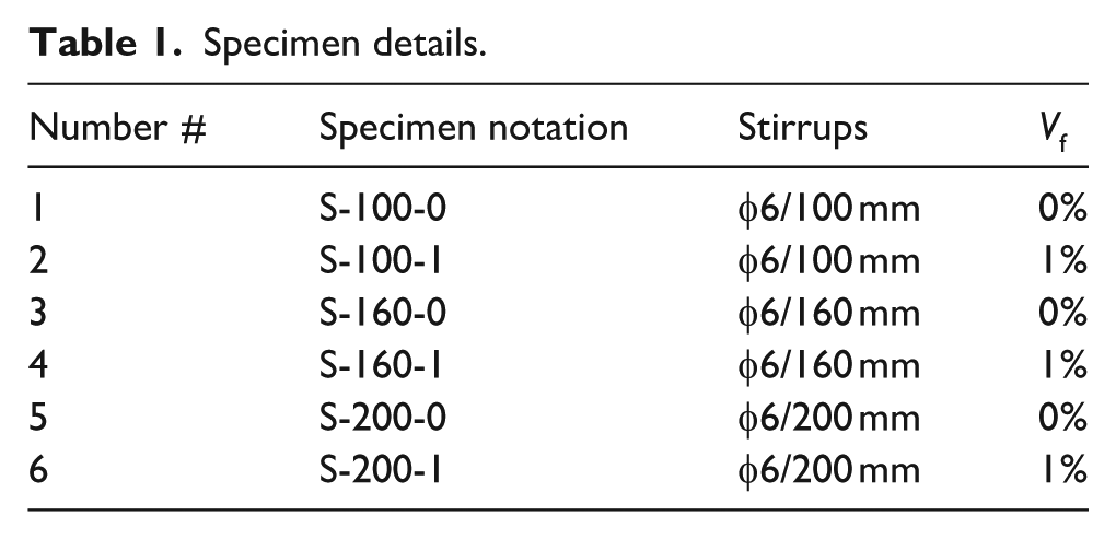
The details of hybrid beams are given in Table 1. The notations of the specimens were composed of the capital letter “S,” followed by two numbers. The first number corresponds to the stirrup specing in mm and the second one to the volumetric fraction of the steel wires in concrete mixture in per cent.
Specimen details.
Materials
The recycled steel wires (RSW) shown in Figure 2 were obtained from waste tires which are generally recycled using a variety of techniques, including the pyrolysis, cryogenic, and shredding processes. Through a succession of shearing and granulating processes, the shredding process lowers the tire to rubber granules and steel wires.
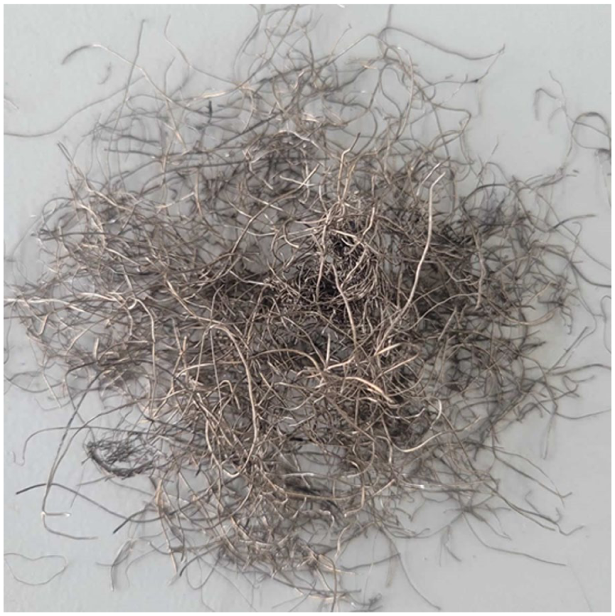
RSW.
The first stage of processing involves chopping or shredding a whole tire until it is divided into pieces that are between 50 and 150 mm in size. The steel containing rubber components are then sent into a second shredder, which separates them into smaller bits. Magnets are then employed to separate the steel from the rubber at the conclusion of this step. The view and mechanical properties of the P-GFRP beams are given in Figure 3 and Table 2. These values are considered catalog values. The aspect ratio of the RSWs used in the experiments was tried to be maintained in a controlled and repeatable manner at a level applicable with the following measures

P-GFRP box profile.
Mechanical properties of P-GFRP. 32

The wires were sieved according to certain length ranges with standard sieve sets, and only the wires remaining in the target range (50–150 mm length) were used (Figure 4).
Since the diameter of the wires is constant, the variability in the length/width aspect ratio stems mainly from the length difference.
All wires used in the experiments belong to the same production batch, and measurements were made on randomly selected wires.

Length ranges of RSW.
Scanning Electron Microscopy (SEM) analysis of the steel wire extracted from waste tires provided critical insights into both surface morphology and geometrical features of the material. The SEM images (Figure 5) revealed a generally even and rough surface texture. Moreover, dimensional analysis conducted on the SEM micrographs showed that the wire diameters varied slightly, typically ranging between 306 and 337 µm. This variation in diameter may stem from manufacturing tolerances or surface wear during usage and recovery. The accompanying Energy Dispersive X-ray Spectroscopy (EDS) analysis provided insight into the elemental composition of the wire (Figure 6). The dominant elements detected were carbon (40.33 wt.%), iron (37.55 wt.%), and oxygen (9.39 wt.%), suggesting the presence of steel as the primary material, with some degree of surface oxidation. The high atomic percentage of carbon (69.38 at.%) is characteristic of high-carbon steel, which is commonly used in tire reinforcements for its strength and rigidity. Minor amounts of copper (7.86 wt.%), zinc (3.88 wt.%), magnesium (0.80 wt.%), and silicon (0.19 wt.%) were also detected. These elements may originate from the manufacturing process or environmental exposure, possibly due to surface coatings or contamination. The presence of zinc and copper may indicate galvanization or other protective treatments, while silicon and magnesium could be linked to trace additions or adhered particles from rubber or road debris.

SEM analysis of RSW.

EDS analysis of RSW.
All beams in the same group (0%, 1% and 2% fiber content) were cast simultaneously to have identical mechanical properties of concrete. 100 × 200 mm cylindrical and 150 mm samples were tested to determine the compressive and splitting tensile strength values of the beams. The cylindrical and cubic compressive strength values were obtained as 25 and 29.5 MPa, respectively, for concrete without fiber content. The cylindrical and cubic compressive strength values were measured as 29 and 34.6 MPa for 1% fiber content, 32 and 38.6 MPa for 2% fiber content. The splitting tensile strength values of the samples with 0%, 1% and 2% fiber content were measured as 2.83, 3.24 and 3.54 MPa, respectively.
The reinforcing bars in the beams were of Grade B420C, which is commonly used in Turkey. The characteristic yield stress, minimum ultimate strength and minimum elongation ratio of this grade are given as 420 MPa, 500 MPa and 14%. To determine the mechanical properties of the reinforcing bars, 2 bar samples with a diameter of 6 mm and two samples with a diameter of 10 mm were tested under uniaxial tension. The experimental stress-strain curves of these bar samples are given in Figure 7. The mean yielding stress values of the φ6 and φ10 bars were obtained as 361 and 424 MPa, respectively, and the mean ultimate strength values as 393 and 520 MPa, respectively.
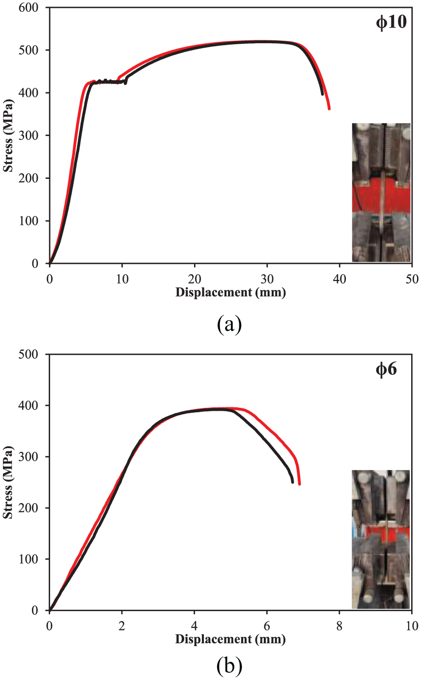
Experimental stress-strain curves of the bar samples.
Burnout Test
An experiment known as a burnout test was performed on the specimens made from the profiles to identify the fiber and matrix ratios impacting the mechanical performance of the P-GFRP beams (Figure 8). The specimen was weighed before testing-the total weight of the GFRP profile sample stood at 743.50 g (Figure 8(a)). Afterward, the sample was kept in an oven, at roughly 600°C, for a duration of about 2 h, so as to get rid of the resin and other organic substances. Such temperature and duration sufficiently degrade the composite matrix yet effectively retain the glass fiber structure. The mass of the inorganic glass fiber residue remaining after the incineration process was recorded as 461.50 g (Figure 8(b)). The tested GFRP profile was determined to contain 62.08% glass fiber.

Burn out test.
Experimental Setup
The hybrided beams were exposed to four-point bending. The shear span had a length of 400 mm, providing a shear span-to-effective depth (a/d) ratio of 2.87. Loading was applied using a servo-controlled hydraulic piston and the vertical deflections of the beams were measured by an LVDT at mid-span. The test setup is depicted in Figure 9.

Experimental setup.
Experimental observations and failure modes
Nine pultruded P-GFRP beam sections damage analysis were examined in the experimental program. The progressive failure damages of each specimen was recorded. The test result failure damage of each sample is shown in Figure 10.

Post-experiment images of damaged specimens to the stirrup spacing of 100 mm. (a) Concrete without reinforcement. (b) 1% steel wires in concrete. (c) 2% steel wires in concrete.
The American Prestandard for Pultruded Fiber Reinforced Polymer (FRP) Structures (ASCE 2020) presents three different modes of failure for pultruded GFRP beams, which are “material rupture,” “local instability” and “lateral torsional buckling.” The concrete infill inside the GFRP encasement prevented the test specimens from experiencing a global mode of buckling, namely the lateral torsional buckling. Furthermore, two distinct modes are defined in the same standard under the influence of shear forces, namely “material rupture” and “web shear buckling.” Finally, the concentrated loading on pultruded beams is stated to trigger four distinct modes of failure, namely “tensile rupture of the web,” “web crippling,” “web compression buckling,” and “flange flexural failure.”
Some of these modes were observed in the test specimens. In Specimen S-160-2, for instance, web local buckling was detected in the constant-moment (zero-shear) region of the beam (Figure 11). This failure might have been related to the “web compression buckling” mode under the influence of concentrated loading, since the buckled part of the web was located in the vicinity of the applied loads. The failure may have also been initiated or triggered by the flexural moments in the central part of the beam. In other words, the failure of the GFRP box of S-160-2 is also associated with the “local instability” modes under the influence of flexural failure.
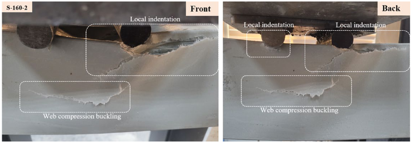
Web compression buckling of the GFRP box in specimen S-160-2.
In the majority of specimens, the failure of the GFRP encasement stems from material rupture. This rupture generally took place in the shear span, meaning that the shear forces are responsible for the final failure. The association of this failure with shear forces is meaningful on the ground of low a/d ratio (2.87) of the test specimens. In S-100-0, S-160-0 and S-200-1, the initial material rupture was observed at the junction between the compression flange and webs and later followed by the rupture at the junction between the tension flange and webs (Figure 12). In the remaining specimens (S-200-0, S-100-1, S-160-1, S-100-2 and S-200-2), on the other hand, the initial material rupture was observed at the tension flange-web junctions, mostly followed by compression flange-web junctions (Figure 13). The rupture at the tension flange-web junction initiated mostly in the central constant-moment region of the beam, implying that this rupture is caused by the flexural tensile stresses. Different from the other beams with sole material rupture, the rupture at the flange-web junctions of S-160-1 was accompanied by web compression buckling (Figure 11), similar to Specimen S-160-2.

Material rupture of the GFRP box in specimens S-100-0, S160-0, S200-1.

Material rupture of the GFRP box in specimen S-160-1, S-100-1, S-200-0, S200-2.
In all specimens, the excessive slip between the RC core and the outer GFRP shell prevented the P-GFRP beams to attain composite action. The waste wires (RSW) could not alter the failure modes of the beams and improve the composite action between the RC core and GFRP shell. The tests indicated that stirrup spacings had greater influence on the P-GFRP beam behavior as compared to the presence and fraction of RSW. Figure 14 shows the load-deflection curves of the specimens without RSW and with 1% RSW.
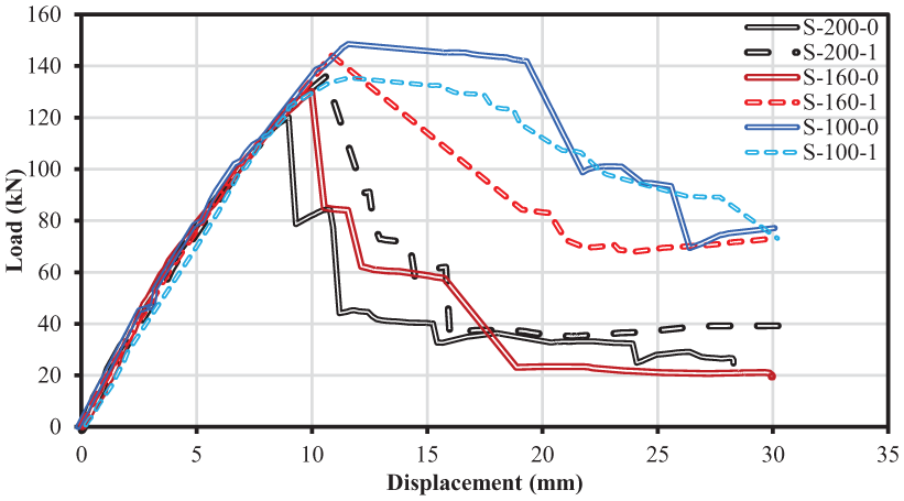
Load-deflection curves of test beams.
The test results of the specimens with 2% RSW were not included in the comparison of the test results and evaluation of the effects of RSW on beam behavior. The reason for excluding these specimens is the heavy levels of concrete segregation in the presence of 2% RSW in concrete mixture (Figure 15). The segregated areas played a key role in the final beam failure. In other words, the specimens with significant concrete segregation failed prematurely. For instance, the crushed portion of concrete compression zone and the diagonal cracks in Figure 15 propagated toward the segregated areas and resulted in the premature failure. Hence, reaching conclusions based on the results of the beams with 2% RSW was considered to be misleading by the authors.

Concrete segregation in some specimens.
The peak load values in Figure 14 correspond to the failure of the GFRP encasement. Upon reaching the ultimate load, the GFRP tube failed and ceased to contribute to the load-resisting capacity of the P-GFRP beam. Beyond the peak, a sudden and abrupt reduction took place in the applied load and a residual load capacity was retrieved after this reduction. The decrease in capacity due to the failure of the GFRP tube and the residual load capacity thereafter depend primarily on the stirrup spacing.
As depicted in Figure 14, the load capacity of the beams underwent a decrease of only 5%–10% in the presence of a stirrup spacing of 100 mm, while a reduction of about 75%–80% was observed with the failure of GFRP in the beams with a stirrup spacing of 200 mm. Independent from the failure type of the GFRP box, the RC beam inside the tube underwent shear-compression failure in all specimens. For the beams with identical stirrup spacing, on the other hand, the beam with RSW maintained a higher load capacity and was capable of undergoing greater deflections at the residual load capacity than the beam with plain concrete. For example, the residual load capacity of specimen S-160-1 was in the order of 50% of its peak load, while specimen S-160-0 maintained a residual load capacity of about only 15% of its peak load in the post-failure stage of the GFRP box. In specimens S-160-0 and S-200-0, the applied load experienced major stepwise reductions in the post-failure stage of the GFRP box, while the reductions of S-160-1 and S-200-1 were more gradual and smooth, implying the significant contribution of RSW in improving the ductile behavior of P-GFRP beams. The quantitative comparison of the test results is presented in the next section with more factual comments.
Independent from the final failure of the GFRP box, the RC core of all specimens underwent shear-compression type of failure (Figure 16). The failure was characterized by severe concrete crushing directly under the loading point, debonding cracks at the tension reinforcement level and diagonal tension cracks combining the two. The failure type clearly indicates that the load-carrying mechanism of the beams was composed of diagonal compression struts extending between the loading points and supports and a tension tie connection the bottom nodes of the struts. This mechanism represents the expected behavior type on account of the low a/d ratio of the beams.

Shear-compression failure in S-160-0.
Figure 14 shows that in beams with 100 mm stirrup spacing, crack control was largely provided by the stirrups since there was already a high amount of shear reinforcement. Therefore, the additional contribution of RSW was limited and no significant improvement was observed especially on the post-peak behavior. On the other hand, in wider stirrup spacing, such as 160 and 200 mm, the contribution of RSW to crack bridging and load transfer was greater due to the inadequacy of internal shear reinforcement. In the presence of insufficient amount of shear reinforcement, the addition of RSW to concrete increased the ductility and energy dissipation capacity in the post-peak region, thus achieving a better load-deflection behavior. In summary, the contribution of RSW becomes more effective in cases where the concrete is not sufficiently confined by the internal transverse and lateral reinforcement restraining effect (in the presence of low shear reinforcement). In the case of 100 mm stirrup spacing, the effect of RSW may have been undermined by the already dominant stirrup performance.
Comparison of test results
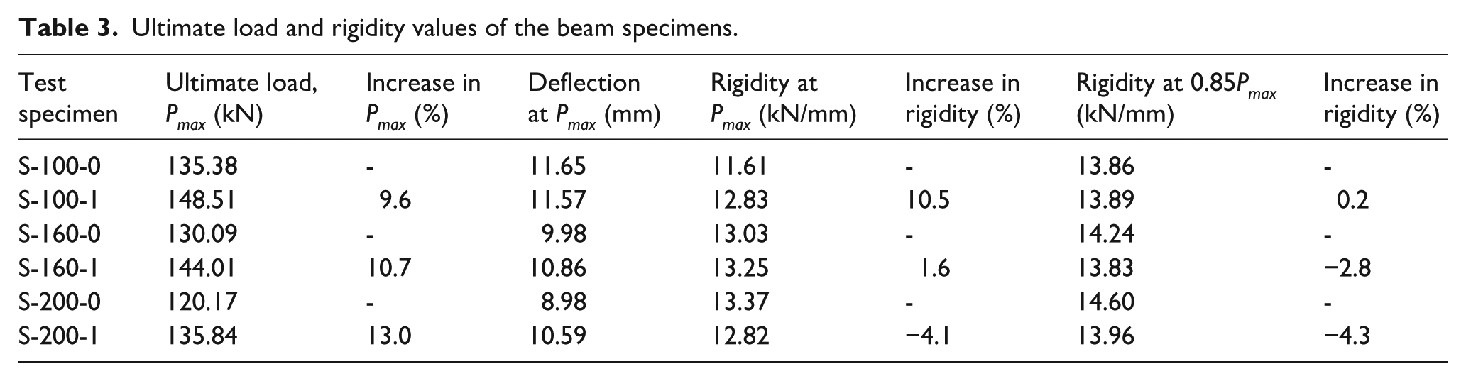
Table 3 tabulates the peak load values, the deflections at ultimate load and the rigidities of the beams. Two definitions of rigidity were adopted in the table. The first definition, denoted as the rigidity at Pmax, is the slope of the secant line connecting origin to the peak point in the load-deflection curve. The second definition, denoted as the rigidity at 0.85Pmax, is the slope of the secant line connection origin to the point corresponding to 85% of the peak load in the ascending branch of the load-deflection curve. Furthermore, the deformation ductility index (DDI) and energy absorption capacity values of the test specimens are tabulated in Table 4. DDI is the ratio of ultimate deflection to the deflection at 0.85Pmax. Three different definitions of the energy absorption capacity were adopted in the present study. The first two definitions (at Pmax and at 0.85Pmax) correspond to the areas under the load-deflection curve up to an applied load of 0.85Pmax in the ascending branch of the curve and up to the peak load value, respectively. The last definition, on the other hand, represents the total area under the load-deflection curve up to the complete failure.
Ultimate load and rigidity values of the beam specimens.
Ductility index and energy absorption capacity values of the specimens.

Deformation ductility index.
Increase in the energy value of each beam to the one of the reference beams with identical stirrup spacing.
By assuming that the longitudinal steel is expected to reach yielding at about a load value of 0.85Pmax, the energy absorption capacity at 0.85Pmax can also be referred to as the modulus of resilience, that is, the ability of a beam to absorb energy in the completely elastic state. Furthermore, the total absorbed energy, that is, the final definition, can also be denoted as the modulus of rupture, which indicates the amount of energy to be absorbed by the beam until failure (elastic energy + plastic energy).
As stated in the previous section, the test results of the specimens with 2% RSW were disregarded in the comparison due to the heavy degrees of segregation in the specimens. The concrete was not distributed evenly in the beams; therefore, there were some gaps, especially in the central portion of the beams. This led to a significant loss of strength due to local failure at segregated areas. In Tables 3 and 4, each specimen with 1% RSW was compared to the reference beam with no RSW content and with identical stirrup spacing. In this way, the contribution of RSW in concrete to the beam behavior could be unfolded for a variety of stirrup spacing values, that is, for different amounts of transverse reinforcement in the P-GFRP beams. The contribution of RSW to the load capacity was found to increase with increasing stirrup spacing, that is, decreasing shear reinforcement ratio. The contribution of adding RSW to concrete increased from about 10% to 13% as stirrup spacing increased from 100 to 200 mm. In terms of flexural rigidity, on the other hand, adding RSW to concrete had positive influence in the presence of closely-spaced stirrups (100 mm), while the presence of RSW in concrete mixture had a negative influence on the beam rigidity in the case of wide stirrup spacing (200 mm). The cracking at the wire-concrete interfaces at earlier stages of loading might be responsible for the adverse effect of RSW on the beam rigidity, since these cracks widen and propagate if the beam is not reinforced with closely-spaced stirrups in transverse and lateral directions. The closely-spaced stirrups prevent propagation of the interfacial cracks and allow the RSW to contribute to the beam behavior even at the later stages of loading.
The contribution of RSW to the energy absorption capacity of a beam does not follow a regular and well-defined pattern. But in general, the addition of RSW to concrete can be said to contribute to the amount of absorbed energy in the elastic state of material behavior, while this contribution is much less in the plastic state. The addition of 1% RSW resulted in an increase of about 64% in the modulus of resilience of the beam with 160 mm stirrup spacing, while this increase reached 72% in the modulus of rupture value. A direct relation of this increase with stirrup spacing could not be set based on the present test results. To be more specific, Figures 17 and 18 indicates that the addition of 1% RSW to concrete mixture had significant contributions to the absorbed energy in both elastic and plastic ranges of displacement in beams with widely-spaced stirrups (160 and 200 mm), while the addition of RSW contributes only to the energy absorption capacity in the elastic state of beam behavior (modulus of resilience) in the presence of closely-spaced stirrups (100 mm). As shown in Figure 18, the important confining effect from stirrups with a spacing of 100 mm results in the RSW to cease its significance after reaching the peak load and undergoing plastic deformations. This finding is in agreement with the experimental findings discussed in the previous section. The RSW content in concrete had no clear effect on the DDI value in the presence of closely-spaced stirrups (100 mm), while this content had negative effect on DDI value in the case of wide stirrup spacing (200 mm).
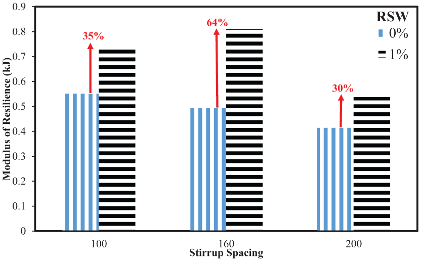
Change in Modulus of Resilience with the Addition of RSW.

Change in Modulus of Toughness with the Addition of RSW.
Analytical study
As explained in Section 2.4, the GFRP encasement parts of the test beams were observed to undergo two distinct modes of failure, namely material rupture and web compression buckling. In a majority of the specimens, material rupture initiated at the junction between top flange and webs in shear spans, meaning that this rupture was caused by shear forces. The American Prestandard for Pultruded Fiber Reinforced Polymer (FRP) Structures (ASCE 2020) presents the following equation for the limit state of material rupture under shear forces:

where FLT is the characteristic in-plane shear strength in MPa and As is the shear area in mm2. The concept of shear area is not clear in ASCE 2020 prestandard. For this reason, the definition of shear area in the American Specification for Structural Steel Buildings, AISC 360-16 (AISC 2016) was used in the present calculations:

where t is member thickness and h is width resisting the shear force, taken as the clear distance between the flanges less the inside corner radius on each side for box section in mm. As suggested by AISC 360-16 (AISC 2016), h was taken as the outside dimension minus 3 times the thickness.
In some of the specimens, material rupture initiated at the junction between the tension flange and the webs in the central constant-moment region of the beam. This type of rupture is clearly caused by the bending moments rather than shear forces since the central portion of the beam is subjected to the maximum bending moment and no shear force. ASCE Prestandard (ASCE 2020) presents the following strength equation for the limit state of material rupture from bending effect for the members that have longitudinal elastic moduli in the flanges and webs within 15% of each other:

where FL is the characteristic longitudinal strength (in tension or compression) of the member in MPa, y is the distance from the neutral axis to the extreme fiber of the member in mm and I is the moment of inertia of the member about the axis of bending in mm4. Based on the loading and support conditions of the test setup, the nominal load (Pn) corresponding to Mn can be calculated from the following equation:

where a is the shear span length, which is 400 mm in the present study.
Finally, the nominal strength of the beams for the limit state of web compression buckling can be obtained from the following equation (ASCE 2020):

where fcr is the critical stress, calculated from the following equation:

where tw is the web thickness in mm, EL,w and ET,w are the characteristic longitudinal and transverse elastic moduli of web in MPa, respectively, υLT is characteristic longitudinal Poisson’s ratio, GLT is the characteristic in-plane shear modulus in MPa. leff is the lesser of web depth and the distance between the vertical web stiffeners in mm. Since the beams did not have any web stiffeners in the present tests, leff was taken as beam depth. The effective area (Aeff) is calculated from the following equation:

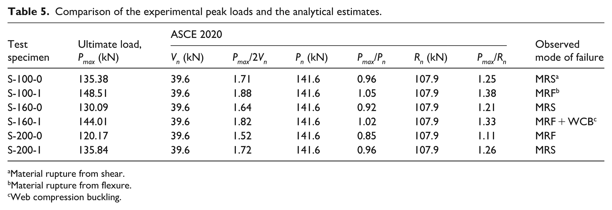
The analytical and experimental load values are tabulated in Table 5. The measured mechanical properties of the GFRP profiles, presented in Table 2, were used in the calculations. The time effect factor (λ) is assumed to be equal to unity in calculations since the test specimens were tested soon after being prepared and service life is not a matter of concern in the calculations. The nominal strength values from code formulations were not reduced with resistance factors and the experimental values were directly compared to the nominal values. In bending moment calculations, the characteristic longitudinal compressive strength was adopted instead of the characteristic longitudinal tensile strength, since FLc is lower than FLt.
Comparison of the experimental peak loads and the analytical estimates.
Material rupture from shear.
Material rupture from flexure.
Web compression buckling.
The tabulated values in Table 5 indicate that the most critical limit state for all beams is the material rupture from shear forces. The nominal strength (Vn) for this limit state was calculated as 39.6 kN. Due to the application of the load at two loading points with the help of a load-spreader beam, the maximum shear force in the beam at peak load (Pmax) was equal to Pmax/2. Hence, Vn was compared to Pmax/2 in the table. The ratio of Pmax/2 to Vn ranged between 1.52 and 1.88.
In other words, the nominal capacity for material rupture under shear forces was well exceeded at the time of failure of the GFRP box. This conclusion is in parallel with the experimental observations. In almost all specimens, the first material rupture took place in the shear spans at the compression flange-web junctions. However, this rupture did not cause the complete failure of the P-GFRP beam, since the RC core started resisting the additional shear forces after this rupture.
The ratio of the experimental peak load (Pmax) to the nominal strength corresponding to material rupture under bending (Pn) varied between 0.85 and 1.05. Moreover, the ratio of the experimental peak load (Pmax) to the concentrated load strength for web compression buckling (Rn) ranged between 1.11 and 1.38. The fact that the nominal strength values for material rupture under bending were in much closer agreement with the experimental peak load values implies that the final failure of the GFRP encasement stems from bending-related material rupture. This finding was also substantiated by the experimental observations. In the majority of specimens, the RC core resisted a greater portion of the shear forces in the beam after the initial shear-related material rupture in shear spans. After a great deal of deformations, the box beam reached its nominal strength under the limit state of material rupture from bending. At this load level, the junctions between the bottom flange and webs ruptured in the vicinity of mid-span due to major bending moments. Beyond this point, the GFRP box lost it load-carrying capacity completely and the reserve load capacity was provided by the RC core. In some of the beams, web compression buckling accompanied the material rupture before complete failure of the GFRP box since the nominal strength for web compression buckling mode was rather close to the experimental ultimate load values of the specimens.
Since the P-GFRP beams showed a clear strut-and-tie type of behavior along the course of loading, the load estimates from strut-and-tie models are expected to be in close agreement with the experimental values. Previously, Shawkat et al. 35 proposed a detailed strut-and-tie model for GFRP box beams with concrete or reinforced concrete infill. By adopting this model to present experimental setup (two loading points on the span), the load capacity can be calculated from the following equation:

where Z is the depth of the truss model, n is the shear span-to-depth ratio of the beam, h is the full depth of the box section, T is the force in the tension tie, obtained from the following equation:

where EL is the characteristic longitudinal elastic modulus of GFRP, Af is half of the cross-sectional area of the GFRP box,

In the original equation developed by Shawkat et al., 35 Ef, denoted as the elastic modulus of FRP, was used instead of EL. However, EL (the characteristic value) is prefered in the present text to render the equation more compliant with the standards. To set the relationship between ε and the shear span-to-depth ratio (a/h) of the beam, Shawkat et al. 35 proposed the following empirical equation:
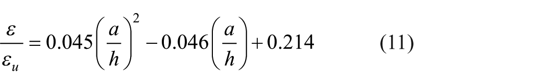
εu is the rupture strain of FRP. The estimates from this formulation are compared to the experimental peak load values in Table 6.
Analytical estimates from strut-and-tie model.

As shown in the table, the theoretical load capacity of the GFRP box beam with RC infill (147.44 kN) is slightly above the load capacity of GFRP box itself (141.6 kN) from material rupture limit state. In other words, the contribution of the RC core seems to be approximately 4% theoretically. But, one should also state that the RC core prevents complete failure of the GFRP box due to the material rupture from shear stresses at a much lower load level (39.6 kN) and helps the box to resist higher loads without losing its integrity until reaching the flexure-induced material rupture and web compression buckling. The small contribution of the GFRP box to the load capacity of the RC core agrees with the findings of Özkılıç et al., 33 who found out that the contribution of the GFRP encasement reduces as the shear span-to-depth ratio of the beam increases and a more-flexure dominated behavior is encountered in the beam.
The ratio of the experimental peak load to the analytical estimate from the strut-and-tie model ranged between 0.88 and 1.01 with a mean value of 0.92 and a percent coefficient of variation of 6.76. Accordingly, the present model provides quite accurate and conservative estimates in the sense that only one of the experimental results exceeded the analytical estimate by only 1%.
Conclusions
The present study deals with the contribution of the RSW to the flexural and shear behavior of P-GFRP beams with RC infill, also denoted as reinforced concrete-filled P-GFRP box beams. The amount of RSW in the concrete mixture and the stirrup spacing of the RC core were adopted as test parameters. A total of nine test specimens with three different RSW ratios (0%, 1% and 2%) and three different stirrup spacing values (100, 160, and 200 mm) were tested within the scope of the experimental program. The longitudinal reinforcement ratio of RC core (1.4% tension and 0.5% compression reinforcement), the dimensions of the P-GFRP encasement (100 × 150 mm box section and 6 mm thickness) and the RC core, the mechanical properties of the constituent materials (P-GFRP box, concrete and steel reinforcement) and the shear depth-to-span ratio of the beams (2.87) were kept identical in all test specimens. The test specimens were compared and the test results were discussed in terms of load capacity, flexural rigidity, deformation ductility and energy absorption capacity criterion. Finally, the experimental ultimate load values of the specimens were compared to the analytical estimates from a strut-and-tie model proposed by Shawkat et al. and the strength equations for the limit states of material rupture and web compression buckling in the American Prestandard for Pultruded Fiber Reinforced Polymer (FRP) Structures (ASCE 2010), since these two modes were observed in the experiments. The following conclusions were drawn from the experimental and analytical stages of the present study:
An RSW ratio of 2% in the concrete mixture is not feasible since the concrete core inside the GFRP encasement is subject to significant segregation for high amounts of fiber in concrete. For this reason, the maximum amount of RSW should be in the order of 1% for proper placement of concrete.
The effect of presence and amount of RSW in the concrete mixture on the flexural and shear behavior of P-GFRP beams was found to increase with decreasing ratio of stirrups in the concrete core. In the present tests, the addition of 1% RSW increased the load capacity of the beam with a stirrup spacing of 100 mm by 10%, while this increased reached 13% in the presence of a stirrup spacing of 200 mm in the concrete core. As the stirrup spacing rises, a smaller amount of diagonal tension cracks are crossed by stirrups and the crack widths increase for this reason. The steel wires play a more crucial role in limiting crack widths and contributing to the integrity of the beam as wider and longer diagonal cracks develop, that is, the spacing between stirrups increase.
Unlike the load capacity, the contribution of RSW to beam rigidity was shown to be more emphasized in the case of closely-spaced stirrups. In beams with wide stirrup spacing, the addition of RSW resulted in reductions in beam flexural rigidity rather than increasing it. The diagonal shear cracks widen and propagate to a greater extent in beams with widely-spaced stirrups. The negative influence of the early-age cracks at the wire-concrete interfaces on these diagonal cracks exacerbate in the case of low stirrup ratios. Adversely, the interfacial cracks are crossed by stirrups and the RSW begins to increase the beam rigidity rather than decreasing it in beams with closely-spaced stirrups.
The presence of RSW in concrete mixture has a greater contribution to the energy dissipation capacity of a P-GFRP beam in the elastic state as compared to the plastic range of material response. In other words, the increase in the modulus of resilience of a beam significantly exceeds the increase in the modulus of toughness with the inclusion of RSW. The present tests indicated that the contribution of 1% RSW to the modulus of resilience and modulus of toughness values were in the order of 130% and 70% for a stirrup spacing of 160 mm.
The deformation ductility decreased with the addition of RSW to concrete in the case of widely-spaced stirrups (200 mm), while the effect of presence of RSW to concrete on deformation ductility was not clear in the case of close-stirrup spacing (100 mm).
The load-displacement curves of P-GFRP hybrid beams can be generally categorized by two main regions. The curve reaches a peak point at the end of an approximately elastic region. At this peak point, the P-GFRP encasement fails and ceases to contribute to the beam capacity and rigidity. The excessive slip between the RC core and the P-GFRP encasement prevents a composite beam behavior to develop beyond the peak point. Immediately after the failure of P-GFRP box, the load capacity suddenly drops to a second capacity and a plateu is followed at this second load capacity. The sudden drop in the load capacity can be as low as 5%–10% in the presence of closely-spaced stirrups (100 mm), yet as high as 75%–80% for wide stirrup spacing (200 mm).
The final failure of the RC core is directly dependent on the shear span-to-effective depth ratio of the core. This failure type could not be altered by the P-GFRP encasement as a result of the relative slip between the two layers, that is, the core and outer box. In the present study, the core of each and every specimen underwent shear-compression failure, characterized by major diagonal cracking between the loading point and the closest support, concrete crushing directly beneath the loading point and debonding cracking in the vicinity of supports at the tension reinforcement level. The formation of two diagonal compression struts, each of which extends between the loading point and the supporting point in the same half-span, and a tension tie extending between the bottom nodes (supporting points) of the compression struts were clearly observed in the experiments. The plateau in the load-displacement curve and residual capacity of beams after failure of P-GFRP encasement correspond to the shear strength of the RC core and plateau ends with shear-compression failure of the RC core.
The theoretical calculations and comparison of the analytical estimates with the experimental ones indicated that all of the specimens experienced material rupture from shear stresses long before the complete failure of the P-GFRP box. However, the RC core prevented the complete failure of the P-GFRP box and helped the pultruded beam to maintain integrity until reaching the material rupture limit state from flexure and accompanying web compression buckling under the influence of concentrated loading. The failure loads of the P-GFRP box beams were in rather close agreement with nominal strength values corresponding to flexure-induced material rupture.
The analytical estimates from strut-and-tie model, which is modified version of the original equation of Shawkat et al., 33 were in rather close agreement with the experimental failure loads of the specimens. The mean ratio of the experimental-to-analytical failure load was calculated as 0.92 and the percent coefficient of variation as 6.79.
The reported effects of the RSW fibers on the beam behavior depend primarily on the quality and mechanical features of the RSW fibers. In case of using these fibers in the concrete mixture in the construction industry, the authors strongly suggest the determination of the flexural tensile strength and compressive strength of concrete by regularly testing concrete samples. These tests should be conducted for each concrete mixture produced from a new delivery of RSW cycles from the recycling facility to safeguard the negative effects of the reduction in the quality of recycled materials.
The present study was designed as a preliminary study and aimed to observe the effects of the parameters comparatively in the first stage. Further experimental studies with full-scale beams are needed to verify the findings of the present study, based on a limited number of specimens, and to strengthen the statistical analyses and reach more specific conclusions. The future studies are also encouraged to contain reference RC beams without GFRP encasement to uncover the contribution of this encasement to the beam behavior.
The interface friction between the GFRP encasement and RC core has a deep influence on the experimental behavior of the test specimens of the present study. However, measuring this interface friction is rather cumbersome, if not impossible. Furthermore, all of the test specimens had comparable and close values of GFRP-concrete interface friction, since the GFRP encasement had a rough inner surface and no slippage took place in the experiments along the interfaces. For all these reasons, the interface friction was not considered as an individual test parameter. In future studies, shear tests or interface stress measurements to quantitatively determine the interface behavior between GFRP encasement and concrete core may be rather helpful in drawing more specific conclusions.
Footnotes
Acknowledgements
The authors are thankful for the financial support provided for this research by the Deanship of Scientific Research at King Khalid University, Abha, Saudi Arabia, through Large Groups RGP2/539/46.
Funding
The authors disclosed receipt of the following financial support for the research, authorship, and/or publication of this article: The study was supported by Ministry of Science and Higher Education of the Russian Federation as part of the World-Class Research Center program, Advanced Digital Technologies (contract No. 075-15-2022-312 dated 20/04/2022).
Declaration of conflicting interests
The authors declared no potential conflicts of interest with respect to the research, authorship, and/or publication of this article.