
Abstract
This study has compared numerical simulations of plain concrete (PC) and mixed steel fiber-reinforced concrete (MSFRC) impact loading results with experimental findings regarding blows needed and impact energy at first crack and ultimate failure. These experimental testing findings were based on a testing protocol that was recommended by ACI committee 544. Hooked end steel fibers of 25 and 50 mm length with 1 mm constant diameter at various volume fraction were combine systematically to get synergistic effect. The findings of an experimental and the computational analyses suggested that raising fiber volume fraction increased an impact resistance of concrete significantly. The numerical simulation replicated experimental data, suggesting that a numerical technique may accurately predict test findings.
Keywords
Introduction
With an increase in strength, the brittleness of normal strength concrete (NSC) becomes more pronounced. Many researchers believe that adding fiber to the cement mixture of high strength concrete (HSC) improves their ductility.1,2 Fiber-reinforced concrete (FRC) is playing essential role in construction and military industries due to its increased application against impact loads. A concrete reinforced with fibers is more resilient to dynamic and impact loads, 3 as well as more ductile in its tensile and flexural properties. 4 Fiber reinforcing also prevents fracture propagation, spallation, and expands concrete matrix’s softening area. Steel and polypropylene fibers are most useful. 5 In FRC, volume fraction (Vf) and aspect ratio (L/d) are significant. FRC fibers bear loads as cracks occur. Fibers often transfer matrix stresses to fibers when load increases. 6
Through mixing, material selection, and structural design, Steel Fiber-Reinforced Concrete (SFRC) has enhanced impact resistance during the previous decade. 7 These innovations benefit dynamic loads in protective barriers, pavements, and industrial floors. Short and long steel fibers synergistically improve SFRC’s impact resistance, making them a research topic. 8 Recent concrete mixing methods improve steel fiber dispersion and orientation. 9 Traditional mixing methods’ poor fiber dispersion generated isolated weak spots and unpredictable impact performance. Recent innovations like high-shear mixers and centrifugal casting evenly distribute fibers, improving concrete homogeneity. 10 Superplasticizers and modified wet-mix processes make the mix workable enough to insert fibers without impacting strength or flowability. 11 Nano-silica strengthens the steel fiber-cement matrix connection, increasing the composite’s energy absorption capacity upon impact. 12 This tight control over fiber orientation and the matrix-fiber interface makes MSFRC a more reliable impact-resistant material. MSFRC steel fibers have altered kind and geometry to improve impact resistance. 13 Research shows that fiber length and aspect ratio affect energy absorption and crack propagation under dynamic loads. 14 Long strands boost load-carrying capacity and fracture bridging at high-velocity impact, while short fibers prevent early-stage cracks and improve post-crack toughness. 15 Hybrid fiber systems perform effectively because they blend short and long fibers. 16 Short fibers prevent cracks, whereas long fibers control crack propagation, improving impact resistance. Through fiber contact, hybrid fiber systems optimize energy dissipation and endurance. 17 This makes MSFRC ideal for blast-resistant walls and machinery coatings. Performance has improved with advanced fiber coating methods. Steel fiber corrosion resistance is improved by zinc, epoxy, and polymer coatings, extending MSFRC structural life in harsh situations. 18 High-impact forces and corrosion are important for maritime impact applications.
MSFRC improvements have improved structural integrity and design flexibility. MSFRC can now be improved for a variety of impact-resistant applications by adapting mix design and fiber arrangement to structural needs. 19 MSFRC’s crack control mechanisms and hybrid fiber systems’ toughness strengthen high-energy-impacted concrete. 20 Impact energy absorption and dissipation limit damage propagation, lengthening concrete structures’ dynamic stress life. MSFRC is suited for bridge decks and industrial floors because short and long fibers synergize to improve impact and fatigue resistance. 21 These developments have offered engineers and architects more design flexibility to build more efficient and optimized concrete structures that meet performance specifications without excess material. 22 Weight and space are important in lightweight protective shells and thin-walled impact-resistant elements. These numerical modeling advances have improved MSFRC design. Impact load-induced hybrid fiber effects and structural reactions are better simulated and predicted. 23 Advanced finite element models (FEM) that recreate matrix and fiber behavior and are validated against experimental data enable precise design predictions without expensive and time-consuming full-scale testing.
Smart innovations in building materials are revolutionizing the construction industry. 24 As research into advanced composites like Steel Fiber-Reinforced Concrete (SFRC) improves, sensors, data-driven monitoring systems, and adaptive materials that respond to dynamic environmental conditions and structural loads become viable. 25 These smart technologies enhance concrete structure impact resistance, sustainability, safety, and efficiency. 26 SFRC, especially when researching the synergistic effects of short and long steel fibers, demands real-time material performance monitoring under different stress conditions. 27 SFRC structural health is monitored via fiber-optic sensors and piezoelectric devices. 28 These sensors measure stress, strain, temperature, and fractures. 29 As concrete experiences impact forces during load-bearing testing or in real-world applications, these sensors provide real-time structural integrity insights. 30 Experimental and numerical investigations like SFRC increase simulation model accuracy. These impact resistance and stress dispersion simulations are improved by smart sensor networks in real life. 31 Future smart cementitious composites like SFRC could collect real-time data to self-sense stress and impact. 32 Self-healing or self-monitoring concrete could detect and respond to cracks or structural deformations, revolutionizing the industry with real-time performance data. 33 These materials evaluate compressive strength, impact resistance, and other mechanical properties automatically. Fiber dispersion, impact absorption efficiency, and localized stress responses can be revealed via steel fibers and implanted sensors. Machine learning can also discover performance and maintenance issues before severe breakdowns in smart SFRC data. 34 This predictive method could create materials that adjust to temperature and humidity, which considerably affect SFRC performance. 35 Future smart cementitious composites will monitor and respond to environmental circumstances. Intelligent SFRC with shape memory alloys (SMAs) or thermoresponsive polymers could dynamically adapt mechanical properties to environmental stimuli. The material may self-heal or harden using embedded materials that change in real time to boost impact resistance in high-stress or impact situations. In seismic or harsh weather constructions, the concrete matrix adapts to stress. 36 This adaptive nature will considerably improve concrete structure longevity, especially in changing environments or with many loading cycles. 37 Structure performance, safety, maintenance, and lifecycle management will increase using smart construction materials like SFRC.38 –41 Concrete monitoring can alert structural engineers to stress levels in real time. Bridges, highways, and high-rise buildings need this early-warning system to avoid catastrophic failures. Smart technologies can test SFRC’s performance under various impact scenarios using numerical simulation techniques like those used to analyze mixed short and long steel fibers, confirming its reliability and efficacy under diverse dynamic loading circumstances.
Recent investigations on Steel Fiber-Reinforced Concrete (SFRC) have improved impact resistance, fracture toughness, and post-cracking behavior employing innovative fiber arrangements and hybrid short-long fiber designs.42,43 These fibers increase tensile strength, ductility, and impact resistance under dynamic loading.40,44 SFRC is increasingly used in applications that need great performance under severe loads, hence experimental methods to analyze its behavior have developed. Studies on synergistic effects show that short and long steel fibers generate a composite material with enhanced impact resistance. 45 SFRC energy absorption, residual strength, and post-impact performance are tested using drop weights, projectile impacts, and high-velocity simulations. 46 Digital Image Correlation (DIC), Acoustic Emission (AE), X-ray Computed Tomography (CT), strain gauges, and infrared thermography are also utilized to monitor damage evolution and detect cracks, fiber-matrix interactions, and stress distributions in real time. 47 These strategies clarify SFRC effect behavior. To reproduce SFRC’s dynamic performance and confirm experimental results, numerical models, especially FEM simulations, are being improved. 48 These mixed fiber model simulations accurately reflect the material’s impact resistance and fracture mechanisms, illustrate the fibers’ synergistic effects, and offer a comprehensive approach to creating more durable SFRC structures. 49
After mechanical testing, cementitious specimen microstructure fracture characteristics are critical to understanding concrete damage distribution and crack propagation. Fiber-reinforced concrete (FRC) fracture surfaces responded differently after impact, showing how short and long steel fibers work together to prevent cracks. Fiber bridging reinforced crack passageways to prevent expansion. Mixed fiber length specimens demonstrated a more complex fracture pattern, with longer fibers enhancing pullout resistance and shorter fibers uniformly dispersing cracks. These findings support experimentally increased impact resistance and energy absorption. Short fibers affect crack course and reduce brittle fracture, as fiber-matrix debonding was more apparent in specimens with a higher volume proportion of short fibers. These fracture characteristics disclose FRC damage distribution methods under dynamic loading circumstances, optimizing fiber designs for impact resistance. Nondestructive methods that account for fracture energy scattering inside the microstructure are essential for understanding crack propagation and damage distribution on the fracture surface. Due to the synergistic effects of short and long fibers, this technique is crucial for analyzing steel fiber-reinforced concrete impact resistance and fracture behavior.
According to tests, concrete with 0.1% to 2.1% polypropylene fibers showed improved impact strength compared to plain concrete into ultimate fracture and initial crack. 50 Samples with higher fiber content (in all aspect ratios) had a higher impact strength, and samples with a higher percentage of hooked-end steel fibers (0.5%/1%/1.5%/2%) had a 38, 55, and 74-fold increase in absorbed energy, respectively, in FRCs with 60, 75, and 83 aspect ratios. 51 In their study, Nataraja et al. 52 employed a drop hammer to assess an impact resistance of SFRC. The concrete had an aspect ratio of 40 and was divided into two strength categories. The initial crack and ultimate fracture impact strength of all samples exhibited an increase in correlation with the volume proportion of fibers. At early cracking and final breakage, the FRC sample had three and four times the impact resistance of normal concrete. For 50 MPa concrete, these values were 7 and 10. Song et al. 53 assessed the properties of HSC and HSFRC using 1% volume fraction of hooked-end steel fibers measuring 3.5 mm in length and having an aspect ratio of 48. The compressive strengths of the fiber-reinforced and reference specimens were 66 and 76 MPa, respectively. Data shows HSFRC and HSC impact resistance enhanced by 10% and 3%, respectively. Bindiganavile 54 examined loading rate and FRC performance. Polypropylene concrete strands exhibited superior impact resistance compared to steel fibers, particularly at higher loading levels. Chen et al. 55 used hybrid BFRP minibars and micro fibers to increase concrete’s mechanical qualities. The hybrid fibers considerably increased concrete’s impact resistance, compressive strength, and splitting tensile strength. Due to their small size, micro fibers commonly broke during microcrack growth. Under a 30% failure probability, the concrete reinforced with hybrid 1.5% BFRP minibars and 0.75% micro steel fibers exhibited the highest splitting tensile strength, compressive strength, and final-fracturing impact life. Ramakrishna and Sundararajan 56 found that steel-fiber FRCs had six times the impact resistance of normal concrete. Studies suggest that fibers, especially steel fiber, improve concrete’s impact resistance. 57 Concrete’s brittleness increases with its strength, which reduces its impact resistance. Fibers in concrete mixtures have been studied to improve ductility, durability, fracture toughness and impact strength, heat and shock strength, and resistance to impact, fatigue, and dynamic loads.58,59 Concrete’s impact resistance can be measured using explosive, drop weight, and projectile impact tests.60,61
Although previous research has investigated the impact of fiber length and volume fraction on the impact resistance of concrete, our research introduces several significant innovations that set it apart from the existing work. 62 There were scarcity of the study on the impact resistance of FRC which include silica fume. 63 Our study explores the synergistic effects of incorporating both short (25 mm) and long (50 mm) hooked-end steel fibers into a single concrete mix, in contrast to the majority of studies that focus on either short or long fibers in isolation. Steel fiber with different length and an 80:1 aspect ratio was employed in current study. Silica fume and Steel fiber were shown toward boost concrete’s energy absorption capacity and ductility.63,64 Specifically, this research has aimed to investigate the impact resistance characteristics of mixed steel fiber reinforced concrete that includes both mono and binary combinations of steel fibers. Fibers dosage varies from 0% to 1.5% by volume to determine the influence of dose and fiber length with use of mixed steel fibers on impact resistance. A comparative evaluation of mono and binary fiber concrete is made on the basis of impact resistance. A numerical simulation was constructed by Alavi Nia et al. 65 to examine the impact strength of different volume fractions of polypropylene fiber and hooked end steel. Drop weight test was used using six cylindrical samples with a diameter of 150 mm and a height of 64 mm. There was a high correlation between numerical simulation and experimental data, and it was found that steel fibers with hooked ends performed better than polypropylene fibers. Deng et al. 66 investigates the two-dimensional microscopic finite element models and mesoscopic numerical simulations to analyze multi-scale polypropylene fiber-reinforced concrete’s mechanical properties. It shows how PF length and dosage affect concrete properties, providing technical applications. Taner Yildirim et al. 67 conducted an experiment where they subjected concrete cubes (100 mm) reinforced with steel, glass, and polypropylene fibers to repeated impact loads. They then assessed the decrease in strength of the cubes using ultrasonic pulse velocity. According to test results, hybrid steel FRC fared well under impact loads. Numerous investigations have shown that steel fibers increase concrete impact resistance.68 –70 In general, explicit methodologies are found more suitable for a dynamic events simulation using the finite element analysis. Nevertheless, they may become computationally expensive if the analysis is prolonged. Then an implicit methodology may be better, and LS-DYNA can specify an alternative integration method. The integration of both experimental and numerical investigations is a unique aspect of the present research. This dual approach enhances the reliability of the findings obtained by the study and also offers valuable insights of numerical simulations for future material design.
In the current study, both experimental and computational methods were utilized to explore the impact resistances of specimens made with and without steel fibers. In addition, it is proposed that empirical model relates impact resistance and hybrid fiber coefficient based on experimental data.
Experimentation: Materials and methods
Mixing proportion
Materials confirming to Indian Standard Specification are used for the non-fibrous control concrete mixture. The construction material used is 53 grade Ordinary Portland cement, which adheres to the specifications of IS 12269:2013. 71 It has a compressive strength of 53 MPa after 28 days. Local river sand with a specific gravity of 2.6 and a fineness modulus of 2.64 is employed as the fine aggregate. Crushed stone aggregate, conforming to IS 383:1970 72 and with a specific gravity of 2.8, is utilized as the coarse aggregate. Conplast SP430 DIS super plasticizer is incorporated into FRC as per specifications of IS 9103: 1999 in order to enhance its workability across all combinations. 73 The steel fibers used in this investigation are hooked end that has a tensile strength of 1020 and 1062 MPa, procured from Stewols India (p) ltd., Nagpur, Maharashtra, India. Two sizes of hooked end steel fibers with an average length of 25 and 50 mm with constant diameter of 1 mm are investigated; their shapes and geometry are shown in Figure 1. Their equivalent aspect ratios are 25 & 50 for separate fibers. The material’s density is shown in Table 1. Table 2 has exhibited the characteristics of steel fiber.

Steel fiber used.
Material used for concrete preparation.

Characteristics of steel fiber utilized.

Methodology for experimentation
Mix design of MSFRC
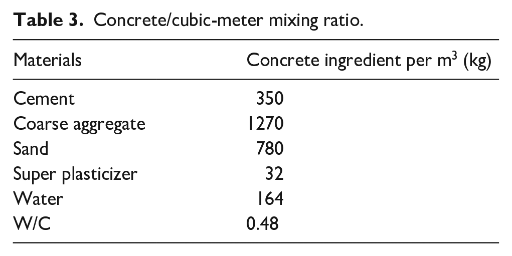
The plain concrete meets IS 10262:2009 74 and 80–100 mm workability. Admixture doses are kept constant throughout the investigation to achieve the desired workability and negotiate the effect of admixture on concrete strength. The detailed proportions of the mixture for the investigations are presented in Table 3. Sixteen series of concrete mixes are used in the experimentation. Concrete composition is identical for all mixtures as shown in Table 4
Concrete/cubic-meter mixing ratio.
Long and short fiber mixed proportion.

C: cement; CA: coarse aggregate; N-S: normal sand; W: water; SP: superplasticizer; LSF: long steel fiber; SSF: short steel fiber.
Table 4 is a list of a MSFRC mixes that are produced. The fiber content of the typical standard FRC mix is around 0.5% by volume of concrete. In MSFRC, this number often rises when the percentage composition of the group grows. As a result, to explore influence of mixed fibers upon the characteristics of MSFRC, steel fibers are added to a mixture in amounts ranging from 0.5% to 1.5% that has a proportion of LSF and SSF indicated in Table 3. In equation (1), Yu et al. introduce the “hybrid fiber coefficient,” which measures the proportion of SSF in fiber. 75

Where: Vs- volumetric amount of SSF, Vl- Volumetric amount of LSF, and Kf- hybrid fiber coefficient.
Mixture method identification
This study thoroughly mixes steel fibers with concrete. A total production time is about to 9 min and 25 s. Furthermore, mixing is carried out using dried and tempered particles in a laboratory. At the time of mixing and testing, the room temperature is maintained at roughly 27°C.
In this experiment, potable water was utilized to mix and cure concrete per Indian Standard IS: 456-2000. 76 The concrete was mixed with 0.5%, 1%, and 1.5% hooked end fiber (short and long length) at a water-cement ratio of 0.48. Their constituents and code parameters are presented in Table 4 for the 16-combination series that were created.
Impact resistance test
Impact tests have been performed on plain concrete and steel fibrous concrete containing varying volume fractions of fibers, with each volume fraction comprising a variable proportion of steel fibers with hooked ends. Each specimen tested was subjected to drop weight impact testing, and the number of blows of the impact hammer required to create the first crack and eventual failure was recorded. The outcomes are presented in the form of tables and graphs. The specimens’ impact resistance was tested as per ACI committee 544 77 recommended protocol. Six cylinders with a diameter of 150 mm and a thickness of 63.5 mm were tested under impact stresses for each mixture. The 13.5 kg hammer consistently struck the specimen on the base plate of the impact testing machine from a distance of 413 mm. Failure strength was measured by the number of hits needed to break the specimen in each test. Each specimen’s impact energy was determined mathematically.
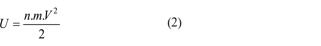


where V is velocity of the hammer at impact; U is impact energy per blow of the hammer; t is time taken by the hammer to fall a height of 457 mm; g is acceleration due to gravity; H is height of fall; m is mass of the hammer and n is a number of blows, m is a mass of hammer.
Results and discussion
Impact energy results and analysis
MSFRC 28-day impact energy is shown in Figures 2 and 3. A designed MSFRC may have better impact strength with steel fibers. The additional steel fibers may slow propagation and bridge fractures. Furthermore, the impact energy characteristics of the specimen are highly influenced by the proportions of LSF and SSF in the overall fiber quantity. The 28-day initial impact energy of concrete having 1.5 volume percent of SSF and LSF (with a Kf value of 0.25) is 325.55 kN-mm, which is the highest recorded for the occurrence of the initial fracture. Short steel fibers (0.5, 1, and 1.5 vol. %) (Kf = 1) have initial impact energies of 94.36, 165.13, and 254.78 kN-mm at 28 days. Maximum impact energy of concrete having a volume percentage of 1.5%, containing SSF and LSF (Kf = 0.25), is 1042.70 kN-mm after 28 days. Short steel fibers (0.5, 1, and 1.5 vol. %) (Kf = 1) have final impact energies of 273.65, 533.14, and 816.23 kN-mm at 28 days. This is explained by the following two factors: (1) Because of SSF are extremely thin and have a significant greater density, they can bridge micro-cracks more influentially. (2) LSF becomes extra energetic in crack bridging when micro-cracks expand and combine in bigger macro-cracks.

MSFRC initial impact energy and hybrid fiber coefficient.
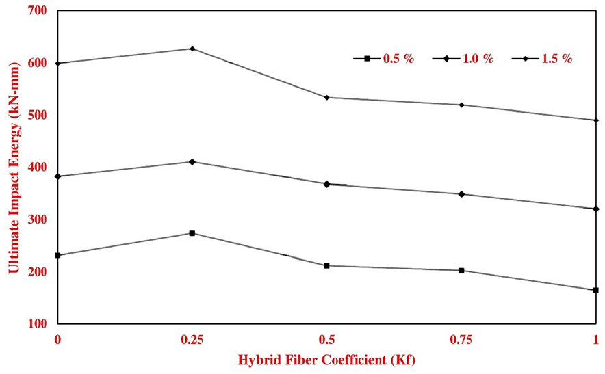
MSFRC ultimate impact energy and hybrid fiber coefficient.
This method may boost ductility and, to a lesser degree, impact strength. LSF may consequently provide a uniform post-peak response. As the fracture width increases, SSF will consequently exhibit reduced energy, although they are increasingly elongated; LSF remain consistently and appropriately aligned between two hypothetical limits when a concrete layer is employed. LSF serves as a barrier for SSF in certain locations, constraining their capacity for evolution. SSF will exhibit improved orientation when combined with LSF compared to its solitary use. Consequently, an increased number of fibers align parallel to the force direction during the impact test, potentially significantly improving mechanical properties. Moreover, it is significant that stress diminishes swiftly following its peak in the sample exhibiting the highest ultimate impact strength. SSF exhibit reduced efficacy in bridging macro-cracks and fail to provide a consistent post-peak response. The impact properties of MSFRC are significantly affected by the ratios of long to short steel fibers.
With the increase in fiber content, the impact strengths of FRC compared to PC for both ultimate fracture and first crack samples improved. Both conventional and high-strength concrete exhibit this result, although ordinary concrete is more pronounced. Steel fibers exhibit enhanced tensile strength and length compared to other fibers. Steel fibers demonstrated a superior improvement in impact strength relative to other fiber types.
Impact strength
Mono steel fiber reinforced concrete
After 28 days of curing, mono steel fiber combinations have 42.86% and 85.72% higher initial impact energy and 44.88% and 88.37% final energy at 0.5% volume fraction. During a 28-day curing period, the initial impact energy of the mono steel fiber with volume percentage of 1.0% grows by 150% and 200%. The ultimate impact energy increases by 211.62% and 162.79% for 100% 50 mm and 100% 25 mm fibers, respectively, in the plain concrete mixture mentioned above. When a volume percentage of 1.5% is added to plain concrete, the impact energy is increased by 285.73% and 357.17% when 100% of 25 and 50 mm fibers are added, respectively. By incorporating 100% 25 mm and 100% 50 mm fibers into plain concrete at a volume fraction of 1.5%, the ultimate impact energy is enhanced by 302.32% and 390.69% respectively.
The initial impact energy required to initiate the first crack in the mono steel fiber is increased by 42.86%, 150%, and 285.73% after adding 100% 25 mm SSF at fiber contents of 0.5, 1, and 1.5% respectively, succeeding a curing period of 28 days. After 28 days of curing, 100% 50 mm LSF increases initial blows by 85.72%, 200%, and 357.17% for fiber content of 0.5%, 1.0%, and 1.5%. Mono steel fiber adding 100% 25 mm SSF increased ultimate impact energy by 44.88%, 168.79%, and 302.32% for fiber content 0.5%, 1.0%, and 1.5% on identical curing days. After 28 days of curing, 100% 50 mm LSF increases initial blows by 88.37%, 211.62%, and 390.69% for fiber content of 0.5%, 1.0%, and 1.5%. The optimal fiber dose for maximal impact strength is determined by MSFRC.
Influence of mixed hybridization
Figures 4 and 5 shows the results of MSFRC mixtures to incorporate binary steel fiber combinations for initial and final impact energy.

Initial impact energy and mixed steel fibers.
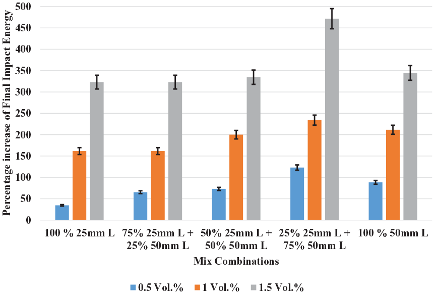
Ultimate impact energy and mixed steel fibers.
After a curing period of 28 days, a mixture of 75% 25 mm and 25% 50mm LSF enhances the impact energy for the initial fracture by 64.29%, 185.73%, and 300% compared to plain concrete for fiber contents of 0.5%, 1%, and 1.5%, respectively. After 28 days of curing, the impact strength of the MSFRC mixture, comprising 50% 25mm and 50% 50mm LSF, increases by 71.44%, 192.87%, and 314.31% for volume fractions of 0.5%, 1%, and 1.5%, respectively, compared to the plain concrete mixture. Figures 4 and 5 illustrate the typical impact strength trends of mixes containing mono steel fibers at different fiber volume fractions over a 28-day period. Comparable patterns are evident in a mixture consisting of 25% 25mm and 75% 50 mm, along with the enhancement in impact strength. The aforementioned plain concrete mixture exhibits percentages of 121.44%, 221.44%, and 392.88% after 28 days of curing for fiber contents of 0.5%, 1.0%, and 1.5%.
Following a 28-day curing period, a mixture including 75% of 25 mm LSF and 25% of 50 mm LSF enhances the impact energy for the initial fracture by 64.29%, 185.73%, and 300% compared to plain concrete, at fiber contents of 0.5%, 1%, and 1.5%, respectively. After 28 days of curing, the impact strength of the MSFRC mixture, comprising 50% 25mm and 50% 50mm LSF, increases by 71.44%, 192.87%, and 314.31% for volume fractions of 0.5%, 1%, and 1.5%, respectively, compared to the plain concrete mixture. Figures 4 and 5 illustrate the typical impact strength trends of mixes containing mono steel fibers at different fiber volume fractions over a 28-day period. Comparable patterns are evident in a mixture consisting of 25% 25 mm and 75% 50 mm, along with the enhancement in impact strength. The aforementioned plain concrete mixture exhibits percentages of 121.44%, 221.44%, and 392.88% following 28 days of curing for fiber contents of 0.5%, 1.0%, and 1.5%.
Numerical simulation of impact resistance
The numerical simulation used the actual dimensions of the spherical steel bar, holder steel ring, and cylindrical concrete specimen. A prismatic bar with a hammer-mass drop weight was envisaged (Figure 6a,b). A hexagonal solid model was used for the specimen and hammer. The sample had 88,652 elements. Since the spherical ball and hammer were firm, their element sizes did not affect the answer. The best number of elements was determined by solving the problem for various mesh elements and counting blows until the initial crack. As the value neared a stable state, the mesh size became optimal. Figure 7 shows the results of plain concrete element size optimization procedures. The sample’s ideal number of elements was 88,562, as shown.

(a and b) Realistic model for FRC concrete in LS-DYNA.

Grid independency for normal concrete.
Material model for concrete
LS-DYNA explicit software version 971 was used for numerical simulations. There are numerous concrete material models in this software. Type 84 Winfrith concrete material model, incorporates impact resistance, is utilized as per CEB’s suggestion. This material model can simulate impact and impulsive loads. 78
Damage criterion
The concrete samples in the simulation were modeled using the Winfrith concrete material model. The modulus of elasticity and Poisson’s ratio of FRCs with volume fractions of fibers were calculated using equations (5) and (6) respectively. An alternative method for calculating elastic modulus and Poisson’s ratio is described in ACI committee 318 77 :


Where EC is a young’s modulus of elasticity,
For the concrete matrix, the failure criterion was the Add Erosion option because there is no realistic model for FRC in LS-DYNA. 78 This option contains various failure criteria, each of which is appropriate for a particular material. Similar to Refs.,79,80 maximum primary strain was employed like concrete failure criterion in this study. Steel fibers in concrete advances tensile deformation performance as well as critical fracture opening. 81 Teng et al. 80 and Tai 79 discovered 0.037 and 0.076 maximum primary strain in plain concrete and FRC. Gu et al. 82 say SFRC can have four times the primary strain of PC. In this impact studies, test was ended once sample’s peripheral surface made contact with a neighboring base, with a maximum displacement of 3 mm.
Boundary and initial conditions
The model employed two types of circumstances: boundary conditions and beginning conditions. Each lower base node must limit Z-axis mobility. Weight was the first condition; the drop must impact the sphere at 3 m/s. See Figure 8 for circumstances.

Boundary condition applied in LS-dyna.
Numerical simulation results
Plain concrete and FRC (mono and mixed fibers) samples with 0.5%, 1.0%, and 1.5% steel fibers were simulated. Figures 9(a-d) to 12(a-d) shows the number of impacts needed to start the crack and finish the fracture for plain and MSFRC. Different steel fiber reinforced concrete types require different strikes. As shown, the first crack occurred at the bottom surface because the number of blows needed to initiate a fracture was generally smaller than at the top surface.

Von-Mises Stresses in non-fibrous Concrete at 4, 6, 9, and 11 number of blows for top and bottom surface: (a) 4 number of blows, (b) 6 number of blows, (c) 9 number of blows, and (d) 11 number of blows.

Von-Mises Stresses in 0.5% SF at 8, 19, 28, and 56 number of blows having Kf = 0.25 for top and bottom surface: (a) 8 number of blows, (b) 19 number of blows, (c) 28 number of blows, and (d) 56 number of blows.

Von-Mises Stresses in 1.0% mixed steel fiber at 15, 34, 79, and 90 number of blows having kf = 0.25 for top and bottom surface: (a) 15 number of blow, (b) 34 number of blows, (c) 79 number of blows, and (d) 90 number of blows.

Von-Mises Stresses in 1.5% mixed steel fiber at 22, 42, 106, and 139 number of blows for kf = 0.25 for top and bottom surface: (a) 22 number of blows, (b) 42 number of blows, (c) 106 number of blows, and (d) 139 number of blows.
On the upper and lower surfaces of the PC and FRC samples, the progression of cracks and fractures to which they led is depicted in Figures 9 to 12. After putting the samples through four impacts with a mixed hybrid coefficient of 0.25, these observations were made after the processes were completed. In addition, these numbers demonstrate that the crack was the initial source of the fracture. Due to the absence of any instrumentation during the experiment, it was not feasible to ascertain the location where the initial fracture began. One of the benefits of using numerical simulation was that it allowed for the identification of the initial crack. There is a connection between this kind of failure and the fact that the FEM 3D mesh does not have axial symmetry. When compared to the other samples, the 1.5% steel fiber sample requires a greater number of blows than the other samples.
Comparison of results
Figure 13(a-b) shows experimental and calculated impact energy at the beginning and end of MSFRC specimen fracture. The specimens were tested for these values. This figure clearly shows that impact energies are little lower than experiments. This is because experiments only identify cracks once they have grown wide enough, but numerical simulations notice them earlier. However, this would have yielded numerical energies lower than those obtained by experiments.

Comparison between experimental and simulation impact energy (kN-mm) (a) initial and (b) ultimate.
Figure 14 illustrates the impact that the total number of blows has on the amounts of stress and strain that are experienced by the simulation. The graph illustrates that an increase in the total number of blows also results in an increase in the amounts of strain and stress that are experienced. In addition, steel fibers, which are distinguished by a hooked end and a higher tensile strength in comparison to plain concrete, demonstrate a higher level of efficiency than the latter component. Both the findings of the simulation and the experimental data showed that the regression coefficient for the beginning crack was 0.9652, and the regression coefficient for the ultimate crack was 0.9982. This indicates that the simulation’s conclusions were in good agreement with the experimental data.
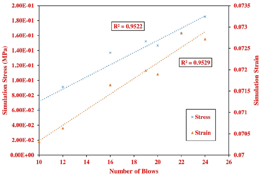
Effect of number of blows on stress and strain of MSFRC.
The simulation’s homogeneity assumption explains the fracture mode differences between tested and simulated specimens. Material sizes and quality can influence the fracture direction as it progresses through the specimens as illustrated in the Figure 15.

Experimental and numerical comparison of concrete specimen fracture modes.
Conclusions
Experiments and numerical simulations were conducted to determine the impact strength effects of various steel fiber volume fractions added to a concrete matrix. ACI committee 544-based drop hammer testing equipment was utilized, and LS-DYNA software was utilized for simulations. Important findings from this study are as follows:
i. Combining short and long hooked end steel fibers in concrete enhances its impact resistance through synergy. 1.5% volume fraction of 25% SF and 75% LF maximizes initial and ultimate impact strength.
ii. Mixed steel fiber reinforcement converts brittleness to ductility in impact failure patterns.
iii. Mixed steel fiber reinforced concrete (MSFRC) is more impact-resistant than single steel fiber reinforced concrete, both at the initial crack and final break. This improves MSFRC energy absorption.
iv. Fragile plain concrete cracked fast, requiring approximately the same amount of strikes for the first and final cracks.
v. For impact loading simulation of FRC and MSFRC, a Winfrith concrete material and Concrete Damage Model with erosion was effective.
vi. Numerical simulation findings matched experimental data, suggesting the approach accurately predicts test results.
The numerical simulations accurately replicate experimental data for several circumstances, although the model’s assumptions and simplifications may impair its accuracy, especially in real-world applications. Simulated conditions like homogeneous fiber distribution and material quality don’t accurately represent concrete mixtures’ complexity.
The results of present investigation, particularly the synergistic effects of short and long steel fibers in mixed steel fiber-reinforced concrete (MSFRC), have the potential of enhancing an impact resistance of concrete in practical applications. For dynamic or impact-loaded structural sections like pavements, bridges, and protective barriers, steel fiber volume fraction increases impact resistance. For varied concrete constructions, present results recommend a mix of short and long fibers in specified amounts to balance impact resistance and cost-effectiveness. Concrete is used in highways, airport runways, military structures, and industrial floors due to frequent or severe impact forces. This study offers insights for various industries.
The efficacy of MSFRC may be influenced by environmental factors and long-term loading conditions in practice, despite the fact that the study does not address these factors. Various prospective research avenues are recommended to address these constraints. Future studies may use more advanced material models that account for concrete matrix moisture, temperature, and aging.
Footnotes
Acknowledgements
The authors extend their appreciation to the Deanship of Scientific Research at King Khalid University (KKU) through the Research Group Program Under the Grant Number: (R.G.P.2/552/45). Additionally, the author expresses heartfelt gratitude to “Stewols India (p) ltd., Nagpur, Maharashtra, India” for supplying hooked end steel fibers for use in the experimental phase of this study.
Ethical Considerations
Not applicable.
Consent to participate
Not applicable.
Consent for Publication
All authors have read and approved this manuscript. All the characterizations, analysis, testing’s related work and testing’s has solely been responsible by Vikrant S Vairagade. Additionally, the raw data can be obtained on request from one of the corresponding authors, Vikrant S Vairagade.
Author Contributions
Conceptualization, VSV, SAD, PB, Sagar Shelare (SS); methodology, VSV, SAD, PB, Sagar Shelare (SS); formal analysis, VSV, SAD, PB, Sagar Shelare (SS), Shubham Sharma (SS); investigation, VSV, SAD, PB, Sagar Shelare (SS); writing – original draft preparation, VSV, SAD, PB, Sagar Shelare (SS); writing – review and editing, Shubham Sharma (SS), MS, AK, DK, MA, JL; supervision, MS, AK, DK, MA, JL; project administration, MS, AK, DK, MA, JL; funding acquisition, MS, AK, DK, MA, JL. All authors have read and agreed to the published version of the manuscript.
Funding
The author(s) disclosed receipt of the following financial support for the research, authorship, and/or publication of this article: The authors extend their appreciation to the Deanship of Scientific Research at King Khalid University (KKU) through the Research Group Program Under the Grant Number: (R.G.P.2/552/45).
Declaration of Conflicting Interests
The author(s) declared no potential conflicts of interest with respect to the research, authorship, and/or publication of this article.
Data availability statement
All the characterizations, analysis, testing’s related work and testing’s has solely been responsible by Vikrant S Vairagade. Additionally, the raw data can be obtained on request from one of the corresponding authors, Vikrant S Vairagade.