
Abstract
Warp preparation is a process prior to weaving that brings all the ends side by side and then winding them on a warp beam with the same tension and length at a predetermined width, density and length. Modern warp preparation machines employ feedback control systems controlling total or individual warp tension. Older warping machines in industry mostly do not have a precise feedback tension control systems and do not match with the quality requirements of today’s market expectations. This paper presents a research in which an individual section beam warp tension control system is explained for converting older beam-assembling machines to a new technology in a direct warping process. The total warp tension of each section warp beam was measured and breaking torque of the magnetic powder brake was adjusted when a deviation occured from the set tension value. It was shown that average loom efficiency increased by 5.65% despite an increase in average loom speed from 663 to 733 rpm in an air jet loom factory. The fabric fault ratio decreased from 3.45% to 1.04% per 100 m of fabric and warp waste decreased from 0.5% to below 0.2% with the new individual section warp beam tension control system adapted to an older version of the assembling machine having total tension control and section warp beam pneumatic brake system.
Introduction
Warp preparation is an important weaving preparation process as it directly affects woven fabric quality and weaving machine efficiency. Three different methods, in addition to ball warping for denim weaving, are used in warp preparation (namely, sectional warping, direct warping and sample warping) depending on the length and color repeat of the warp prepared. Direct warping is used in the preparation of warps with high length and single or only limited color pattern as in terry fabric production. Direct warp preparation, widely used in home-textile, terry and denim weaving industries, is a two step process and has its own machines. These are direct warping process and its machine which prepares section warp beams at high lengths and low warp densities and the assembling process and machine used for joining section warp beams to obtain the warp beam at the required density (weaver’s beam) for the fabric to be produced. If, for example, 40 ends/cm weaver’s beam is required and section beams are wound with 5 ends/cm density, a total of eight section beams is required to join and produce weaver’s beams. A much longer warp is wound on section warp beams and hence a certain number of weaver’s beams (like 5–6) is prepared from these (8) eight-section warp beams. In some applications, warp-on-section beams are sized, dried and then joined on assembling machines.
For a good quality warp preparation, all ends need to be wound at the same length and the same tension. As the direct warp preparation process is completed in two steps, the same length and the same tension conditions should be satisfied at both process steps. Even when the same length is wound to all section warp beams, a change in tension with diminishing bobbin diameter can cause winding of section warp beams with differing diameters. If total warp sheet tension is measured and the same control signal is sent to all the section warp beam breaking units of the assembling machine, there might be tension differences between the warp yarns of different section beams. These tension differences are caused by diameter differences and also by differences in the coefficient of friction in breaking mechanisms. Feeding warp yarns from section warp beams with different tensions in assembling machine ends up with some beams exhausting earlier than the others. The remnant warp on section warp beams cannot be used and becomes warp waste. Depending on the level of tension differences between section warp beams in an assembling machine, fabric quality and weaving machine efficiency are adversely affected, too. Individual tension control of all section warp beams on an assembling machine improves tension control system performance and minimizes the tension differences between section warp beams. Therefore, fabric quality and weaving machine efficiency are increased while warp waste is minimized despite the higher cost of individual section beam warp tension control. Assembling machines manufactured today have individual tension control systems for all its section warp beams. Total warp tension of each section warp beam is measured by a load cell and each section warp beam is braked by an electric motor or a magnetic brake.1,2 But there are many assembling machines running in industry which do not have individual tension control for section-beams. These are relatively older machines. Replacing the older technology assembling machines with the new technological ones requires a costly investment. Alternatively, the older assembling machines can be converted to the new technology by developing individual tension control systems for section warp beams. When the literature was reviewed, no specific research was found regarding tension control systems on assembling machines. There are, however, some publications on tension control of warp drawn from a creel and its mathematical analysis and also tension control in unwinding and winding units of film and web roll-to-roll transfer systems.
Çeli̇k et al 3 investigated the performance of a step motor driven tension control system for warp yarns supplied from bobbins in a creel. After explaining the design detail of the tension control system, they concluded that the tension control system eliminated the tension increase due to diminishing bobbin diameter. Fernando and Kuruppu 4 developed a mathematical model to investigate the tension at different points on a creel from balloon breaker to creel exit. After carrying out the calculations, they concluded that warp tension increased by around 12.65 and 21 cN for 20 and 40 tex yarns respectively at 400 m/min unwinding speed and stressed the importance of using a feedback tension control system to keep it at the desired level. Su and Zhang 5 developed a tension control system for unwinding roller of cylindrical filament winding. The unwinding roller motor was driven as a brake and resisted the rotation of the unwinding roller. Dynamic motion equations were derived and parameters were expressed with respect to the changing radius of the unwinding roller. They investigated the performance of the feedback tension control system using a dynamical integral PID controller and showed that the tension control system performed shorter transition period and smaller overshoots. A better steady-state performance compared to traditional PID controller was also reported. Stoyanov and Nyagolov 6 developed analytical equations for winding to and unwinding from rolls. They could calculate the running (or actual) roll diameter, band or web stretching and linear velocity. These calculations were included in the control algorithms to regulate linear velocity and tension of the running band.
There is some research work on tension control systems in the web, band or film winding/unwinding systems using modern control approaches like adaptive, self-tuning, fuzzy logic and adaptive H∞ robust control. Some of them are reviewed for the benefit of developing tension control systems of warp-assembling machines. Wei et al 7 developed a tension and linear velocity control system for two rolls unwinding and rewinding systems. They used two servomotors for driving unwinding and rewinding rollers and the latest technology controller. They adopted a parameter tuning method for PID tension and PID velocity controllers and concluded that linear velocity and tension were controlled by ±0.2 mm/min and ±2 N deviations from the desired values. This control system performance was found to be sufficient for industrial systems. Kadik and Wang 8 explained the performance of a web winding/unwinding tension control system based on a novel control strategy. The proposed adaptive H∞ control system effectiveness was verified with experimental test results. It was shown that the developed new adaptive controller accommodated parameter variations in the system and improved tension control system performance. Zhang et al 9 developed a new control system technology for composite tape winding. They used a robust extended Kalman filter (REKF) based fuzzy PID controller in addition to the conventional fuzzy PID controller. They concluded that simulation and experimental results showed around 40%–42% increase in the precision of tension control system performance. Chen et al 10 explained the performance of nonlinear web tension control system for a roll-to-roll printed electronic system. The nonlinear dynamic matrix control (NDMC) based on an autoregressive and moving average (ARMA) model is introduced to eliminate the tension disturbance. To evaluate the effectiveness of the proposed control method, the tension control using the traditional (PID), fuzzy PID and proposed NDMC were simulated with MATLAB for performance comparisons. A prototype was also built for performance tests. It was concluded that the experimental results validated the effectiveness of the proposed control scheme.
Design, construction and manufacture of an individual section beam tension control system are explained in this paper for warp assembling machines. Its tension control performance and outcomes are discussed by considering tension variations from full to empty section beam, weaving machine efficiency, warp yarn waste and fabric quality data. Tension control system was adapted to an older assembling machine having pneumatically controlled brake system and total warp tension control. The machine was already in operation in the factory and had 16 section beam units. Therefore, a total of 16 independent section warp beam tension control systems were installed. All the performance data were collected under industrial conditions in the factory.
Working principle of an assembling machine
As shown schematically in Figure 1, an assembling machine consists of a beam stand (

A warp assembling machine main units (
Design of individual section warp beam tension control system
Figure 2 shows pneumatically controlled brakes in assembling machine warp beam stand which was in use in the factory warp preparation department. The machine had a total warp tension control system and pneumatically controlled band brakes (
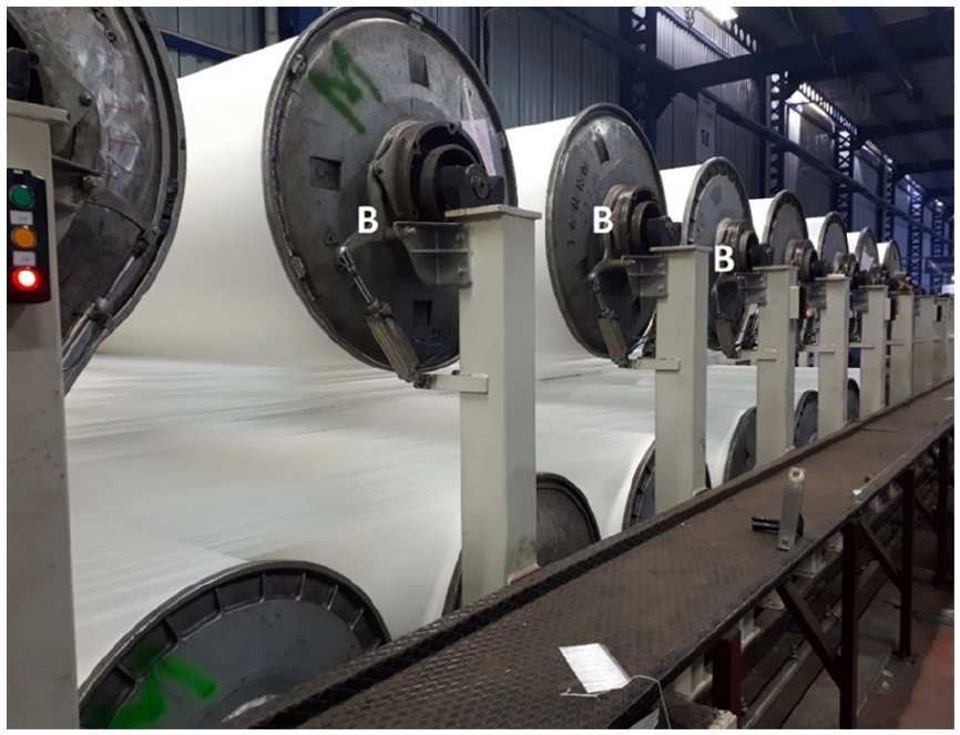
Section beam breaking unit with pneumatically controlled band brake (Picture taken in the factory,
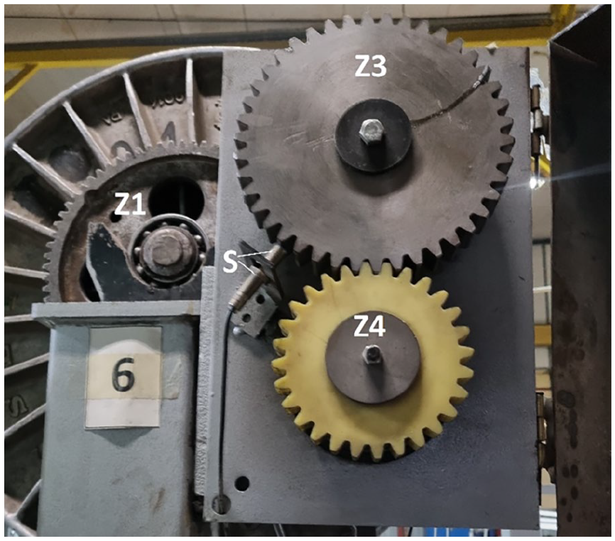
In the design of new tension control system, pneumatically controlled band brake systems were removed from all the section warp beam units and new magnetic powder brakes (

Where,

Magnetic powder brake on the machine and motion transmission mechanism between section warp beam and magnetic powder brake (Picture taken in the factory,
Angular velocity of magnetic powder brake shaft is increased due to the gear ratio (i) and therefore the reflected torque (MT) at the brake shaft decreases at the same ratio. As the warp beam diameter (r) decreases during operation, it is necessary to adjust the required braking torque generated by magnetic powder brake to keep warp tension constant or at its desired value.
A magnetic powder brake consists of a stator which accommodates a winding, a rotor and fine metal particles (powder) having magnetic property. When current flows through the stator windings, magnetic field is produced and magnetic powder particles are aligned between the stator and rotor in the direction of the magnetic field (in radial direction). Hence a strong magnetic coupling is formed between the stator and rotor. This magnetic coupling acts against the rotation of rotor and forms a resistance or brake to the rotation of the section warp beam. The amount of magnetic brake is dependent on the stator current and the magnetic brake torque-current characteristic. For choosing the correct magnetic powder brake, its maximum torque capacity is determined firstly. The machine installed in the factory had a maximum 2000 mm beam width and 5 ends/cm warp density upper limit was considered. Each end was assumed to have a maximum 50 cN (0.5 N) operation tension as the thickest warp in the company was 300 denier. Maximum section beam diameter was taken as 1000 mm and the gear ratio from the beam to the magnetic break was 4.56. In this case, the reflected torque at the magnetic powder-brake shaft was calculated as follows:


According to a maximum 200 m/min winding speed, the angular speed of the section warp beam changes between 63.7 and 318.3 rpm during warp beam diameter change from 1000 to 200 mm. With 4.56:1 gear ratio, this is reflected to the magnetic powder brake shaft as 290.5–1451.5 rpm. Therefore it is expected that magnetic powder brake should be able to run up to 1500 rpm speeds and to produce maximum torque of 55 Nm. Based on these technical parameters, Mitsibushi type ZKB-5HBN magnetic powder brake was selected. A picture and the torque-current characteristic of the selected magnetic powder brake are given in Figure 4. As seen from the curve presented, the powder brake can produce 50 Nm torque with 1.4 A current and 70 Nm torque with 2.0 A current. The tolerable rotational speed for the magnetic powder brake is given as 1800 rpm. 11

The chosen magnetic powder brake and its torque-current characteristic. 11
It is necessary to measure section warp beam tension and warp diameter for each section beam continuously during the warp assembling process to realize individual tension control for all section beams. Diameter measurement of section beams must be monitored to adjust the required braking torque for the desired section beam total warp tension. An inductive switch (


where,
Section beam angular velocity measurement system and pulses produced by inductive switch (Picture taken in the factory,
Winding speed is adjusted by the winding unit and it is kept constant from empty to full beam under a speed control system already existing on the machine.
Tension measurement in each section warp beam was carried out using “S” type load cell (

Section warp beam tension measurement by “S” type load cell (Picture taken in the factory, B: Magnetic powder brake,
A PLC was used as the control and monitoring unit for the warp assembling machine. A PLC software was developed to execute feedback control algorithms as well as other machine functions. Figure 7 shows block diagram of feedback tension control system for each section warp beam. Tension signal measured by the load cell (Vout) is transmitted to the PLC and compared continuously with the set or desired tension signal (Vin). The difference (error signal, e) is sent to PI (proportional + integral) controller in the PLC. The controller output is the control signal (Vc) applied to the magnetic powder brake driver. The control signal is amplified in the driver circuit and converted to the output current. The magnetic powder brake produces the torque (Mb) corresponding to this current according to the curve in Figure 4. Final block in the diagram is the sectional warp beam and warp tension is determined based on the torque applied by the magnetic powder brake and the measured beam diameter. This feedback circle continues until the section beams get exhausted. Trials were conducted with different proportional and integral coefficients and optimum values were determined. The parameters seen on the block diagram are defined below.
Vin: Set tension signal (volt)
Vout: Measured tension signal (volt)
e: Error signal (difference between the set and measured tension signals) (volt)
Vc: Control signal applied to the amplifier of magnetic powder brake (volt)
Mb: Magnetic braking torque (Nm)
MT: Warp tension drive torque (Nm)
MN: Net torque (=MT − Mb) applied to section warp beam (Nm)
T : Total section beam warp tension (N), f: Encoder output frequency (Hz)
K: Conversion coefficient and R: Section warp beam radius (m)

Tension feedback control system block diagram.
Parameters, like warp tension and winding speed, are set and monitored from the PLC screen as seen in Figure 8. In addition, section warp beam diameters, breaking percentage (which is the percent ratio of the running current to the brake maximum current), total number of ends, warp yarn linear density, tension of all sections and average tension per end are displayed. During unwinding, these data are updated with small time intervals such as 5 s. A mobile phone camera was used for video recording of PLC screen to obtain the warp tension change during start up and stop periods of the machine and the data were recorded manually by freezing the camera screen with a desired time intervals like 1 s. For long term tension change, picture of PLC screen was taken with a larger time intervals corresponding to like 5 mm change in section beam diameters. Subsequently, the data were recorded from the pictured screens and the curves were plotted.

PLC screen and displayed parameter for 20 section beams.
Performance analysis of the new tension control system
Performance of the new tension control system is explained below by considering
- Tension change from full to empty section beam for all sections,
- Tension change in all sections during the machine start up period,
- Loom stop rate and efficiency and fabric quality analysis,
- Warp yarns remaining on section warp beams at the end of the warp assembling process,
Tension measurements from full to empty section beams were carried out during warp preparation with polyester yarn. Warp parameters are given in Table 1.
Warp parameters used in performance tests.

Tension change from full to empty section beam for all sections
In the assembling machine, the diameters are measured along with warp tensions in all section beams. As the measured diameters of all section beams are very close to each other, an average diameter was calculated and the corresponding warp tension of each section beam was recorded. During warp assembling, the winding process stops because of end breaks and during weaver’s beam change after every winding completion. During stop periods, the warp tension changes in all section beams. The latter was not included in long term tension variation analysis and the measured warp tensions of all section beams were plotted with respect to the averaged section warp beam diameter (Figure 9). The set warp tension is 17 cN/end and as seen from the curve, warp tension per end remains within ±1 cN of the set value from 66 cm (full) to 32 cm (empty) diameters for all section beams. This indicates a good feedback tension control system performance. The control system performance was obtained for all the section beams and the difference between them remained also within ±1 cN. This is shown in Figure 9 with 10 different curves of 10 section beams positioned mainly on top of each other.

Warp tension-section beam diameter relation for 68/24 polyester warp.
Tension change in all sections during the machine start-up period
It is expected in an assembling machine that warp tension deviates at a minimum level from the set value during stop and start up periods. As it is essential to keep the stopping period as short as possible after an end break, special algorithms for tension control should be applied to prevent excess tension reduction due to the inertia of section warp beams. Similarly, special tension control algorithms are required during start up of the machine after a warp break or weaver’s beam change. Therefore, in contrast to the steady state period in which PI control algorithm is applied, mathematically defined specific control algorithms were used for start up and stop periods. During the start up period, the breaking moment applied to section warp beams was set to the value just before stopping. Subsequently, the control algorithm was shifted to PI control after the set winding speed was reached. During the stop period, much higher braking moment than that of normal running was applied initially, followed by a decrease as the section warp beam was slowed down. Figure 10(a) and (b) show winding speed curve and tension change curves during the start-up period. Already available speed control system on the assembling machine was used in such a way that the set winding speed was reached within 90 s. As Figure 10 shows, the winding speed increased almost linearly with respect to time and tension in all section beams reached at the set value (17 cN/end) within 5 s approximately. The tension curves showed more variation within the first 80 s of the speed transition period, followed by lower variation when stable operation was reached. The transition period of tension curves is much shorter when compared to the speed transition period.

Winding speed and tension change during start-up period of the assembling machine: (a) winding speed change and (b) tension change.
Loom stop number, efficiency, and fabric quality analysis
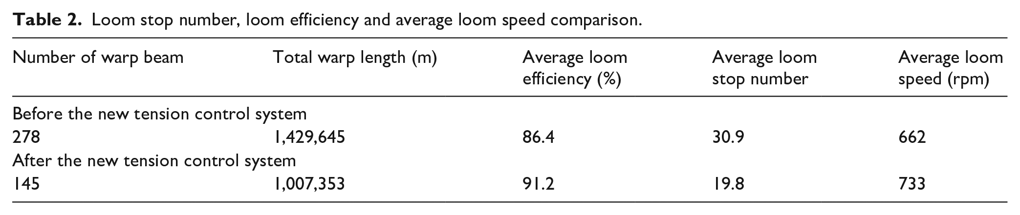
The new tension control system performance was also tested by recording loom stop number and efficiency as well as fabric quality data. All the looms in the company were equipped with an online loom data monitoring system and loom stop numbers and stop periods, type of loom stops due to warp or weft yarns, position of warp stops due to the selvedge and ground warps were continuously recorded and monitored online. Hence, loom efficiencies in percentage were calculated based on total stop period and total running time. Efficiencies and total loom stop data in all looms were taken for the fabrics woven with old and new warps. For this purpose, warps were prepared with the older assembling machine and the stop number and efficiency of the loom running this warp were recorded. At the same time, the number of fabric faults was collected from the fabrics woven with this warp. Data collection was repeated for 278 different warp beams in the factory running with air-jet looms. The total warp length in 278 warp beams amounted to 1,429,645 m. The same fabric with plain weave was woven with all these warp beams. After converting the assembling machine with the new tension control system, 145 warp was prepared with a total amount of 1,007,353 m in length and the same fabric was woven in the same group of air-jet looms. In the same way, loom stop number and efficiency along with the number of fabric faults were recorded and the results are presented in Table 2. As seen from the table, the air-jet looms could run at 662 rpm with an average efficiency of 86.4% and an average loom stop number of 30.9. Average loom efficiency and average loom stop number were calculated as the average values of 278 warp beams. As higher loom speeds increased the loom stop number and reduced the efficiency, an average 662 rpm loom speed was taken as a compromise between loom efficiency and loom production rate in the factory for this fabric. A total of 145 warp beams were prepared with the new tension control system and fabrics were woven with the same group of air-jet looms. The recorded loom running data are given at the bottom line of Table 2. Despite 10.7% increase in average loom speed, the average loom stop number decreased from 30.9 to 19.8 (35.9%) and average loom efficiency increased from 86.4 to 91.2 (5.6%). As air-jet looms are the most sensitive weaving machines to tension differences between warp ends, the individual warp beam tension control system minimized tension differences between section warp beams, as seen in Figure 9, and as a result, reduced number of loom stops and increased loom efficiency. At the same time, the production rate increased about 11.0% in addition to 5.6% increase in loom efficiency.
Loom stop number, loom efficiency and average loom speed comparison.
Quality inspection was carried out for fabrics woven with the above-mentioned two groups of warps in fabric quality inspection machines installed in the company. During inspection, defect type and fabric length at which defect occured were recorded. Fabric quality classification was decided in terms of number of defects per 100 m. About 1,209,507 m of fabric woven with warp prepared by the warp assembling machine having the older tension control system. About 42,782 fabric faults were counted which amounted to 3.45 faults per 100 m of fabric. In the second group of fabrics woven with warp prepared by the same assembling machine with the new tension control system, 821,179 m of fabrics were inspected and 8510 fabric faults were recorded. This amounted to 1.04 fabric faults per 100 m. Hence, a very significant amount of increase (around 70%) in fabric quality was achieved with the new tension control system.
Warp yarn remaining on section beams at the end of the assembling process
It is required that the warps remaining on section beams at the end of the assembling process are kept at a minimum level. Remnant warps are treated as waste material for the company. Tension differences between section warp beams are mainly responsible for the remnant warps left on the other section beams when the first section warp beam gets exhausted. Waste warp materials were recorded over a year period before the warp assembling machine was converted to the new tension control system. This was calculated as around 0.5%. After the new tension control system, average waste was reduced to below 0.2% level. This constitutes a significant gain for the company. Average waste was even lower, nearing 0.1% when warp was prepared with full section warp beams. Table 3 shows the amount of waste warp material on section warp beams for a warp preparation example. Each section of the warp beam had 802 ends and 29,873 m of warp.
Waste warp remaining on section warp beams.

Conclusion
A new individual section warp beam warp tension control system was developed for direct warp preparation assembling machines and adapted to a warp assembling machine already having total warp tension control and pneumatically controlled brake system. Pneumatic brakes were replaced with magnetic powder brakes and tension of all section warp beams was measured by separate load cells. A PI controller was adopted for steady state running of the warp assembling machine. Proportional and integral gains were determined for minimum deviation from the set tension value during regular running. During the start-up period, magnetic powder brakes are set to constant braking torque calculated from the desired total tension and beam radius. When the assembling machine reaches its set speed, PI control algorithm takes control of the process with proportional and integral gain values used before the machine stop. During the stopping period, a higher braking torque is applied to oppose to the inertial moment of section warp beams as well as the torque of total section beam tension. The assembling machine with the new tension control system run mostly within ±1 cN deviation during regular running and without slack and excess tension during stop and start-up periods. Hence, the assembling machine equipped with the new tension control system started serial production in the factory and good quality warps have been prepared with yarns from 40 to 330 denier. The following gains were recorded in the factory with the new tension control system.
- Average loom efficiency increased from 86.4% to 91.2% by 5.65% despite an increase in the average loom speed from 663 to 733 rpm in air-jet looms running in the factory.
- Fabric inspection records showed a significant decrease in the number of fabric faults from 3.45% to 1.04% per 100 m of fabrics as new tension control system minimized tension differences between section beams.
- The amount of warp yarn remaining on section warp beams (waste warp) decreased from around 0.5% to 0.2%. These ratios decreased toward 0.1% when all the section beams ran with full diameters.
This research results showed that adapting individual section warp beam tension control system to older version warp assembling machines increased the economy of the warp preparation process at a significant degree, as was listed above. These quality and economic advantages were gained with a lower investment compared to investing in a new warp assembling machines.
Footnotes
Acknowledgements
Authors would like to thank TÜBİTAK for the support of this research. Authors also thank KARESİ POLYESTER VE PETROKİMYA A.Ş. for their support of the research and covering publication charge.
Declaration of conflicting interests
The author(s) declared no potential conflicts of interest with respect to the research, authorship, and/or publication of this article.
Funding
The author(s) disclosed receipt of the following financial support for the research, authorship, and/or publication of this article: This research was carried out in KARESİ POLYESTER VE PETROKİMYA SANAYİ A.Ş. with the support of TÜBİTAK (TEYDEB 1501 project, project no: 1313609).