
Abstract
At the microscale, a unit cell model of axially-reinforced three-dimensional five-directional (3D5D) circular woven composite materials was established based on the spatial topology of the unit cell. This model considers the changes in cross-sectional shape of the yarns due to mutual compression and incorporates periodic boundary conditions for the circular unit cell. Combining this unit cell model with an progressive damage approach and failure models for the yarn bundles, a strength prediction model for the axially-reinforced 3D5D circular woven composite materials was developed. The model was used to simulate the damage evolution of the fibers and matrix under progressively increasing tensile loads. The tensile strength predicted by the strength prediction model is 420 MPa, with a deviation of 5.12% compared to the experimental value. The failure modes of the axially-reinforced 3D5D circular woven composites are predominantly fiber tensile failure and fiber-matrix interfacial cracking. The damage evolution sequence shows that matrix failure occurs first, followed by fiber-matrix interfacial cracking, and finally fiber tensile failure.
Keywords
Introduction
3D5D circular braided composites with axial yarn addition represent a novel type of circular braided composite material that enhances the axial strength by adding yarn in the axial direction. The equipment used to produce the 3D circular braided fabric is a circular braiding machine. 1 The braiding process for the 3D circular fabric is quite similar to the classical 3D rectangular braiding process, employing the same four-step method. 2 However, in the 3D circular braiding process, the longitudinal movement in rectangular braiding is replaced by radial movement, while the transverse movement is transformed into circumferential movement. The 3D5D circular braided composite material is an extension of the 3D4D circular braiding process, achieved by introducing a fifth directional yarn (axial yarn) that remains straight and stationary along the braiding and forming direction. Compared to laminated composites, the yarns in these 3D5D circular braided composites interweave not only within the plane but also in the thickness direction, thereby offering superior transverse, interlaminar, and shear properties. 3 In comparison to three-dimensional (3D) rectangular braided composites, circular braided composites are easier to form in a single step for circular components, minimizing or eliminating fiber damage caused by mechanical machining. As a result, 3D5D circular braided composites with axial yarn addition exhibit better and more stable mechanical properties, making them highly promising for applications in aerospace, marine engineering, energy, and other fields. 4 Due to the complex structure of 3D circular braided composites and the various stress states and damage modes they exhibit under load, it is essential to conduct research on the mechanical performance prediction of these materials. Establishing a reliable strength prediction model will facilitate an accurate understanding of the mechanical properties of 3D5D circular braided composites with axial yarn addition. This will aid in their application in load-bearing components and in the optimization of structural designs, 5 while also advancing theoretical development related to novel composite materials. Consequently, theoretical prediction work on the mechanical properties of 3D5D circular braided composites with axial yarn addition is of significant theoretical and practical importance.
Currently, both domestic and international research primarily focuses on plate-like specimens, with theoretical studies conducted at macro and meso scales using unit cell finite element methods to investigate the mechanical properties of 3D braided composites. Researchers such as Zuo et al., 6 Zhang et al., 7 Fang and Liang, 8 Zhang and Liu, 9 and Song and Li 10 have employed the Tsai-Wu criterion, Hashin failure criterion, and Mises criterion to predict the strength of 3D4D rectangular braided composite structures. The findings suggest that the Tsai-Wu tensor criterion is an ideal strength criterion for assessing damage in braided fiber bundles, while the Hashin criterion is unsuitable for this purpose, particularly for larger braiding angles. Different braiding angles exhibit varying damage mechanisms: composites with small braiding angles primarily experience fiber tensile failure, resulting in brittle fracture and high strength. In composites with larger braiding angles, fiber bundles are under non-uniform tensile stress, and the tensile strength is predominantly governed by the matrix strength and the transverse strength of the fiber bundles, leading to lower tensile strength. Tian et al., 11 Du et al., 12 Xie et al., 13 and Zhu et al 14 have predicted the strength of 3D5D rectangular braided composites and studied failure modes for different braiding angles. For smaller braiding angles, the primary failure modes are tensile failures of braided and axial yarns. For larger braiding angles, the primary failure mode shifts to tensile shear failure of the braided yarns. Juraszek 15 and Liu et al. 16 using the orthotropic composite cylindrical shell theory, applied the principles of calculating 3D effective elastic moduli of composite laminates, damage mechanics theory, and multi-layer solid elements to develop a finite element model for composites. This model was used to study the occurrence and development of strength and damage, examining the impact of winding angles on performance. Fu et al 17 and Lu et al 18 investigated the progressive damage of 2.5D layer-to-layer angle-interlock woven composites under quasi-static tensile loading. They developed representative volume elements to predict the strength of 2.5D woven composites. The tensile stress-strain curves and damage evolution patterns of woven composites were predicted based on damage failure criteria for fibers, matrix, and fiber-matrix interface. The numerical model’s accuracy was validated through typical experiments, showing that the damage characteristics of the fiber-matrix interface significantly influence tensile strength. Wang et al 19 investigated the mechanical properties of 3D woven composite materials for subsea pressure hulls. Using a multiscale finite element method (FEM) and theoretical approaches, they studied the effects of the radius-to-thickness ratio and initial defects on the 3D woven composite spherical shells under external hydrostatic pressure. Two typical 3D woven structures were selected: 2.5D shallow interlaced bending and 2.5D shallow interlaced straight connections. The results demonstrated that the proposed multiscale finite element method can accurately predict the strength and buckling behavior of 3D woven composite spherical shells under external pressure loads, and the results were compared with theoretical predictions.
In the existing literature, research on the strength of 3D braided composites primarily focuses on 2.5D woven composites, 3D braided plate-like composites, and laminated cylindrical composites. Due to the complex internal structure of 3D circular braided composites, there have been few reports on strength prediction methods and related failure mechanisms for these materials. Therefore, it is necessary to establish a strength prediction model specifically for 3D circular braided composites. This study focuses on 3D5D circular braided composites with axial yarn addition. From the perspective of micromechanics, a unit cell model that considers the mesostructure of the components is established. Based on the progressive damage analysis method, a damage and failure criterion for 3D5D circular braided composites with axial yarn addition is developed. Finally, a strength prediction model for these composites is established. Through simulation, the tensile strength of carbon fiber/resin matrix 3D5D circular braided composites with axial yarn addition is predicted, and the damage evolution behavior of braided yarns, axial yarns, and the matrix during the failure process is described.
Materials and methods
Materials
The motion patterns of yarns in 3D circular braided composites
The carriers in 3D circular braided composites are arranged in an mÕn configuration, where m represents the number of carriers arranged circumferentially (i.e. the number of layers), and n represents the number of carriers arranged radially (i.e. the number of columns). The additional carriers only move within the inner and outer layers of the circumference. During the braiding process, the main carriers that hold the braided yarns alternate their movement in both the circumferential and radial directions, with adjacent layers or columns moving in opposite directions. In contrast, the carriers that hold the axial yarns move only in the radial direction, with no movement in the circumferential direction. The motion pattern of the 3D5D circular braided composite is similar to that of the 3D5D rectangular braided structure. The difference lies in the use of a polar coordinate system for the 3D5D circular braided composite and the circumferential arrangement of yarn carriers on the braiding machine.
The braiding process for 3D circular braided composites employs a four-step method. The main carriers, which hold the braided yarns, move in an interlaced pattern both circumferentially and radially, as illustrated in Figure 1. Here, “∘” represents the braided yarn, and “•” represents the axial yarn. The motion trajectory of these carriers resembles a zigzag line, with the carriers oscillating back and forth between the internal region and boundary regions (i.e. each layer) based on the direction of the trajectory. Typically, the carriers pause for one step upon reaching a boundary region before reversing direction and returning to the internal area. In this repeated back-and-forth movement, the carriers pass through all the boundary regions (i.e. all layers) and, after a certain sequence of movements, return to their starting position. The carriers holding the axial yarns move along an arc from point A to point B. Upon reaching point B, the carriers pause for one step before moving from B back to A. Similarly, they pause for one step upon reaching A before repeating the cycle. The motion trajectory forms the arc AB, and after completing four steps, the carriers holding the axial yarns return to their initial positions.

Kinematic behavior of 3D circular woven preforms.
The horizontal projection of the trajectory for 3D circular braided composites is shown in Figure 2. In this figure, the curves represent the in-plane motion trajectories of the braided yarns, while the axial yarns are positioned straight along the cylindrical axis 20 and arranged circumferentially. Based on the corresponding motion patterns, it is possible to define representative volume elements and further delineate these representative volume elements into inner surface regions, internal regions, and outer surface regions. The yarn trajectories on the surface regions are connected with the yarn motion trajectories in the internal regions, providing a basis for establishing the unit cell model.

Horizontal projection trajectory of the braiding pattern in 3D circular woven composites.
The preform of the 3D5D circular braided composite specimen was fabricated through braiding and subsequently impregnated with resin using the RTM process. The 3D5D circular braided composite specimen is shown in Figure 3. The testing machine used was an MTS 370 (with a maximum load capacity of ±100 kN for the force sensor), and the corresponding extensometer was an MTS 634.12F-24. The gauge length between the two clamps of the extensometer was 25 mm, as illustrated in Figure 4.

Physical photograph of the 3D5D circular braided composite specimen.

Experimental setup photograph of the 3D5D circular braided composite specimen.
Strength prediction model for axially yarn-increased 3D5D circular braided composites
Basic assumptions of the meso-scale model
Assumptions for the unit cell geometric structure
As shown in Figure 5, the horizontal projection of the unit cell for axially yarn-increased 3D5D circular braided composites can be approximated as a sector-shaped cross-section. To enhance computational efficiency and convergence, the sector-shaped cross-section is simplified to an isosceles trapezoidal cross-section. As demonstrated by equations (1) and (2), the overall volume of the unit cell remains unchanged before and after the simplification. 21

Comparison of the fan-shaped cross-section area and the simplified trapezoidal cross-section area of the unit cell.
Cross-sectional area of the sector:

Cross-sectional area of the trapezoid:

The simplified model facilitates easier computation and is advantageous for further studying the mechanical properties of 3D circular braided composites.
(i) The braiding process is stable, and the braided structure is uniform,
(ii) The braided fiber bundles maintain a straight trajectory in space due to the selection of smaller elements,
(iii) Although the actual cross-section of the braided yarn is elliptical, its complexity in finite element modeling and high computational cost lead to simplifying the cross-section to a polygon, specifically assumed to be hexagonal in this context.
Topological structure of the unit cell model
The unit cell of the axially yarn-increased 3D circular braided composite can be divided into four sub-regions. The height of the unit cell, known as the flower length, is denoted as h, and the wall thickness of each sub-region is Wh. The internal structure of the axially yarn-increased 3D circular braid consists of a spatial network formed by fibers oriented in different directions and axial yarns along the radial direction. The arrangement of the yarns in the four sub-regions of the unit cell is illustrated in Figure 6. The angle between the braided yarns and the braiding direction is referred to as the internal braiding angle, is denoted as

Four subdomains of the unit cell model of 3D5D circular braiding of axial yarn.
The axial yarns in the unit cell of the 3D5D circular braiding with axial yarns distributed at the corners of the four subdomains and aligned parallel to the forming direction. The angle between the motion trajectory of the braiding yarns in the horizontal plane and the radial line of the preform is given by equation (3).

Where
The distance from the position point of the braiding yarn at the

Where
The relation for determining the position of the braiding yarn at the innermost layer of the preform is given by equation (5).

Where
Since the unit cell is simplified from a fan shape to an isosceles trapezoid, the cross-sectional width of the unit cell is given by equation (6).

Where
The thickness of the unit cell is given by equation (7).

The internal braiding angle of the unit cell is given by equation (8).

Where

Cross-sectional shape of the unit cell model
The cross-sectional shape of the woven fibers in axially reinforced 3D5D circular woven composites is generally elliptical before tightening. After tightening, the shape transitions between a sector and a triangle. 22 Post-tightening, the cross-sectional shape of the woven fibers becomes an inscribed hexagon within the original elliptical shape, while the axial fibers exhibit a triangular cross-section, as illustrated in Figure 7(a) for the woven fiber cross-section and (b) for the axial fiber cross-section.

Cross-sectional shapes of the braiding yarns and axial yarns. (a) the woven fiber cross-section, (b) the axial fiber cross-section.
The semi-major and semi-minor axes of the ellipse are denoted as
The equation of the line corresponding to the inclined edge of the inscribed hexagon is given by equation (10).

The fiber cross-sectional areas of the woven yarn bundles and the axial yarns, denoted as S3 and S4 respectively is given by equations (11) and (12).


Where
The cross-sectional dimensions of the microscopic unit cell geometry model for the axially reinforced 3D5D circular woven composite material can be obtained using equations (11) and (12).
Establishment of the unit cell geometry model
A unit cell model for the axially reinforced 3D5D circular woven composite material has been established, with a fiber volume fraction of 46% and a braiding angle

Geometric model of the unit cell for 3D circular braiding composites: (a) unit cell model, (b) unit cell fiber bundle model, and (c) unit cell matrix model.
Meshing
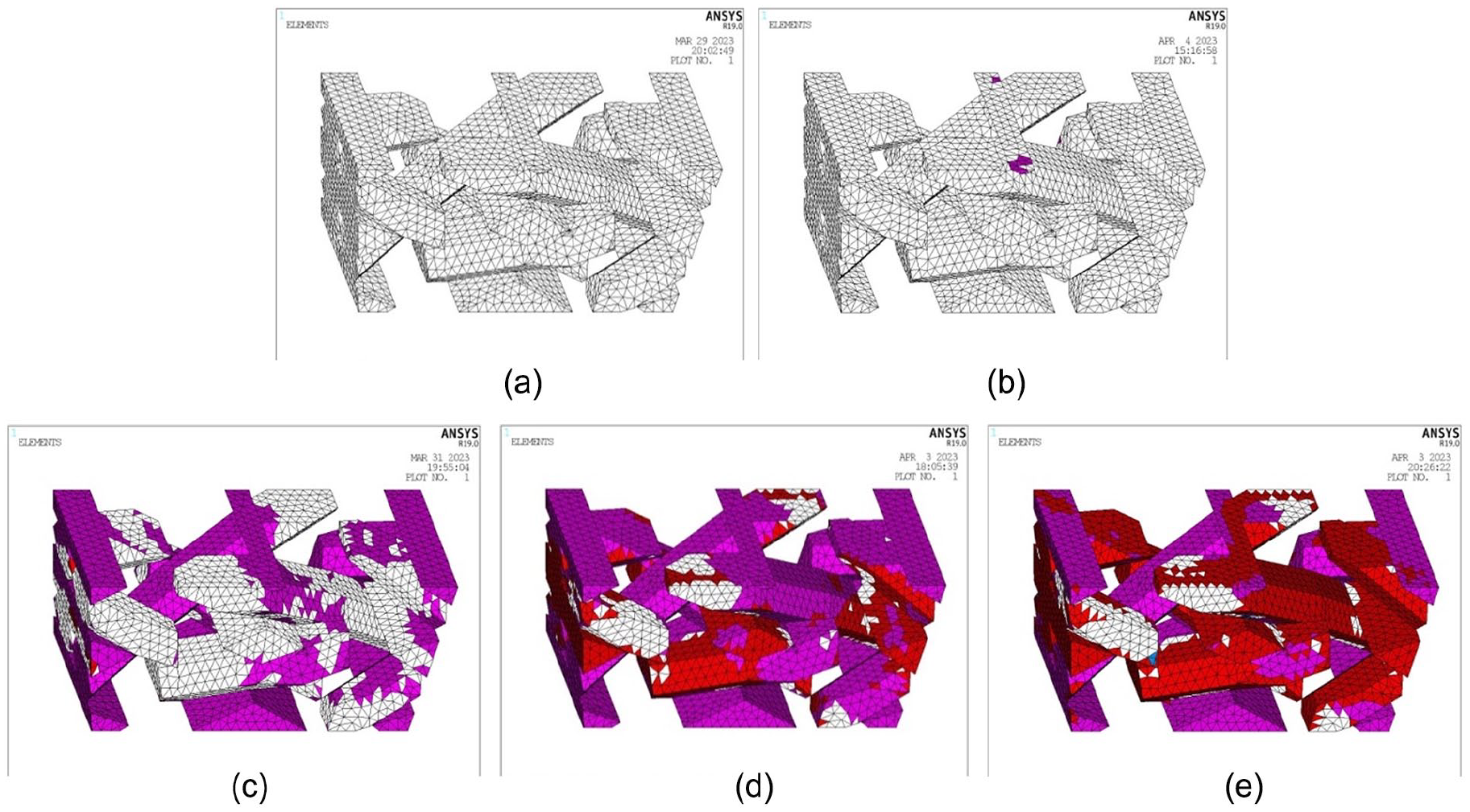
A tetrahedral 10-node element was employed to discretize the unit cell model, with a mesh size of 0.05 mm. The resulting mesh model for the 3D circular woven composite is shown in Figure 9.

Mesh model of the unit cell for axial reinforced 3D5D circular braiding composite materials.
Boundary condition handling
The internal structure of the axially reinforced 3D5D circular woven composite exhibits periodicity. To ensure that the unit cell model accurately reflects this periodicity, appropriate boundary conditions must be applied to the finite element model. These conditions ensure stress and displacement continuity across the boundaries of the unit cell model. Typically, these conditions consider the relationship between the average strain of the unit cell structure and the nodal displacements. They are particularly applicable to periodic unit cells with parallel and paired boundaries, thereby ensuring consistent deformation and stress across the model. 24 The expression for these boundary conditions is given by equation (13).

Where
Considering that the unit cell model of the axially reinforced 3D5D circular woven composite has a trapezoidal structure, the periodic boundary conditions for the unit cell are applied as shown in Figure 10.
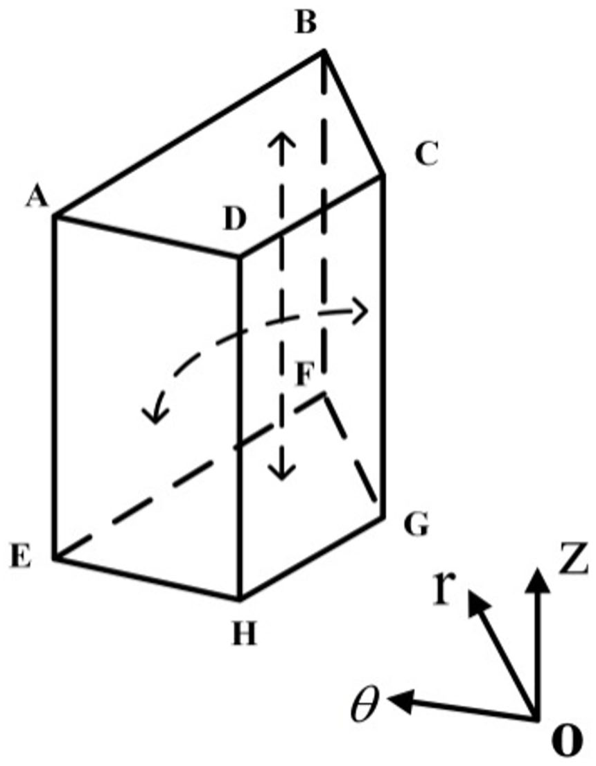
Schematic diagram of periodic boundary conditions for the unit cell model.
As shown in Figure 8, the boundary conditions for the planes ABCD and EFGH in the unit cell model are given by equation (14).

For the boundary conditions of the planes ADEH and BCFG are given by equation (15).

Where
Failure criteria
Fiber bundle failure criteria
Under tensile loading, the axially reinforced 3D5D circular woven composite material exhibits various failure modes. The Hashin failure criterion accurately describes the failure modes of the components within the composite material. Based on the unit cell model established in this study, the Hashin failure criterion is further refined to determine the failure modes of the different components in the composite material. The specific forms are as follows.
(i) Fiber bundle tensile failure (

(ii) Fiber bundle-matrix interfacial cracking failure (

(iii) Fiber bundle-matrix shear failure (

Where
Matrix failure criteria
In the case of axial-reinforced 3D5D circular woven composites, the matrix is generally considered as isotropic material. The failure of the matrix can be assessed using the Von Mises criterion. The specific expression for this criterion is given by equation (19).

Where
Stiffness degradation during the damage process
During the progressive damage process, the initiation of failure is caused by the increase in the applied load. Consequently, in the established micromechanical unit cell finite element model, the corresponding elements undergo stiffness degradation. The degradation mechanisms for each material component in the model are implemented as follows.
(i) Tensile failure of individual elements in the fiber bundle: the performance parameters
(ii) Cracking failure of fiber-matrix interface elements: the performance parameters
(iii) Shear failure of fiber-matrix interface elements: the performance parameters
(iv) Tensile failure of individual elements in the pure matrix: the parameters
Final failure criteria for 3D circular woven composites
Based on the failure characteristics of the axial reinforcement 3D5D circular woven composites, the criteria for final failure determination are defined as follows: the average stress in the unit cell cross-section no longer changes with increasing load, or the fiber bundles have completely penetrated through the entire cross-section of the unit cell.
Strength prediction methods and calculation procedures
The computational process for predicting the strength of the axial reinforcement 3D5D circular woven composites is illustrated in Figure 11. Initially, the geometric model of the unit cell is determined using the topological structure and cross-sectional shape formulas, followed by mesh discretization. Periodic boundary conditions are then applied, and loads are introduced to perform stress analysis of the unit cell model. Subsequently, the load is incrementally increased while evaluating the failure of the unit cell elements according to the established damage failure criteria. Finally, the strength of the axial reinforcement 3D5D circular woven composites is determined based on the material’s ultimate failure criteria.

Flowchart for strength prediction calculation.
Strength prediction and results analysis
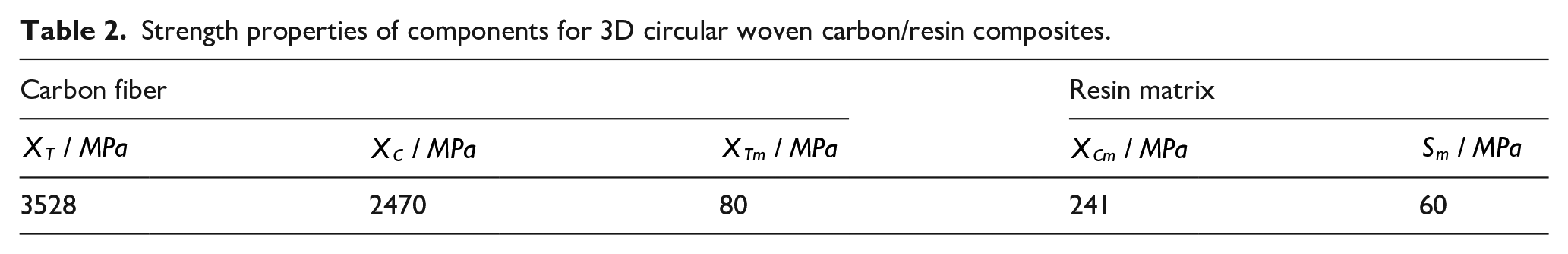
The mechanical properties of carbon fibers and resin matrices are summarized in Tables 1 and 2.
Elastic properties of components.

Strength properties of components for 3D circular woven carbon/resin composites.
The stress of the fiber and matrix models within the unit cell of the axial reinforced 3D5D circular woven composite material was calculated, and the stress distribution within the unit cell was analyzed. The stress distribution for the fiber and matrix models is illustrated in Figure 12. As shown in Figure 12, the majority of the stress is concentrated on the axial fibers, with relatively less stress distributed across the matrix. Stress tends to concentrate at the intersections between the woven fibers and the axial fibers.

Stress distribution contour map of the unit cell: (a) overall view of the unit cell, (b) fiber bundles within the unit cell, and (c) matrix within the unit cell.
Based on the computational flow outlined in Figure 11 and the parameters provided in Tables 1 and 2, the tensile strength of the carbon fiber/resin matrix axial reinforced 3D5D circular woven composite material was predicted. The predicted results and experimental results are compared in Table 3. The component damage propagation is illustrated in Figures 13 and 14.
Comparison of simulated strength predictions and experimental values for axial reinforced 3D five-axis circular woven composites.

Damage progression in the fiber bundle region during tensile testing of carbon fiber/resin-based axial-fiber-reinforced 3D five-axis circular braided composite material: (a)

Damage evolution in the matrix region during the tensile process of carbon fiber/resin-based axial-flux 3D5D circular woven composite: (a)
Figure 13 illustrates the damage progression in the fiber bundle region of the carbon fiber/resin matrix axial reinforced 3D5D circular woven composite material. As shown in Figure 13, at strain level
Figure 15 illustrates the damage progression and proportion of different components (fiber and matrix) in the carbon fiber/resin matrix axial reinforced 3D5D circular woven composite material. Figure 15 shows the proportion of damage to each component of the axial fibers as it progresses. The rate of damage expansion in the pure matrix is faster compared to that in the fiber bundle. At a strain of 0.012, the pure matrix reaches complete failure. Initially, damage in the fiber bundle progresses slowly; however, as the tensile load increases, the damage in the fiber bundle expands rapidly. By the time the material experiences complete failure, matrix damage within the fiber bundle reaches 70%, and fiber damage within the bundle reaches 43%. Once the damage reaches a certain level, the rate of damage expansion slows down. Additionally, when fiber rupture occurs, the composite material is considered to have reached complete failure.

Changes in the proportion of fiber and matrix damage in carbon fiber/resin-based axial fiber-reinforced 3D5D circular braiding composites.
In Table 3, it can be observed that the error between the predicted values obtained from the proposed prediction model and the experimental results is 5.12%. The primary reasons for this error are as follows: (a) the spatial configuration of yarns in the 3D5D circular braided composite specimens exhibits a certain degree of curvature, whereas the prediction model in this study assumes the yarn structure to be straight, neglecting these curvatures; (b) the cross-sectional shape of the yarns in the 3D5D circular braided composite specimens is altered due to mutual compression, leading to discrepancies compared to the hexagonal cross-section assumed in the model.
Conclusion
The conclusions drawn from this study are as follows:
(i) The tensile strength of 3D5D circular braided carbon fiber/resin composites was predicted using the established strength prediction model. The predicted tensile strength showed a relative error of 5.12% compared to the experimental results, indicating the high accuracy of the prediction model. In the simulated damage progression, damage to the pure matrix occurred at strain
(ii) According to the damage proportion diagram, it can be observed that the damage propagation of carbon fiber/resin-based 3D circular braided composites intensifies as the applied load increases. Among the components, the matrix exhibits a faster damage propagation rate, while the damage rate of the fiber bundles remains relatively stable. The proportion of shear damage is minimal, and the tensile failure of the fiber bundles is identified as the primary cause of the material’s ultimate failure.
Footnotes
Declaration of conflicting interests
The author(s) declared no potential conflicts of interest with respect to the research, authorship, and/or publication of this article.
Funding
The author(s) received no financial support for the research, authorship, and/or publication of this article.