
Abstract
In the interest of reducing the weight and also cost of blade skins, various automatic preform manufacturing processes were developed including tape laying, filament winding and braiding. Among them, the circular braiding process was found to be an efficient method in producing seamless preforms on mandrels with various geometries. In this regard, an attempt was made to produce a carbon fiber reinforced composite with the shape of NACA 23018 airfoil using a circular braiding machine. Thus, suitable wooden mandrels were manufactured using NACA 23018 airfoil coordinates, which were obtained by assuming the perimeter of 20 cm. Furthermore, both biaxially and triaxially braided preforms were produced and subsequently impregnated with epoxy resin through an appropriate fabrication method. To assess their performance, four-point bending test was carried out on samples. Ultimately, the elastic response of braided composite airfoils was predicted using a meso-scale finite element modeling and was validated with experimental results.
Keywords
Introduction
For the first time, aircraft structures were made of fiber reinforced composites in large-scale back in the 1960s due to the intrinsic and unique properties of composites including lightweight, tailorable properties, and high specific mechanical properties [1–3]. With the ever-growing development of new production techniques such as tape laying, filament winding and braiding, fiber reinforced composites have found applications in various industries [4]. McCarthy et al. [5] assessed these three mentioned production techniques while manufacturing blade skins. They concluded that braiding technique was more efficient than the others in terms of production rate, the woven structure, no slippage during braiding and exhibiting better resistivity against impact. In braiding technique, there are two distinctive classes named as two dimensional and three dimensional braiding. The former can produce biaxially/triaxially tubular or flat braided preforms. The circular braiding machine, which forms the tubular ones, can produce near-the-net shaped performs with high rate of production compared to conventional methods (prepregs and automatic tape laying).
In the early 1980s, NASA, National Aeronautics and Space Administration, as a pioneer company in developing composite materials with the perspective of aerospace based applications, embarked on some research programs with the aim of assessing the capability of textile based composites as an efficient way to construct aerospace related structural parts. The low out-of-plane properties and also high manufacturing cost of conventional methods made NASA to focus more on available automated textile techniques including weaving, braiding, knitting and stitching [6]. One of their most important programs named as ACT, Advanced Composites Technology, started in the late 1980, aiming at developing composite production methods [7]. In this respect, NASA made some contracts with companies to develop new composite production methods which would meet the requirements demanded by the industries [8]. Composite parts reinforced with braided preforms, which were taken into consideration in both Boeing (ATCAS or “the Advanced Technology Composite Aircraft Structures”) and NASA (ACT or “Advanced Composite Technology”) programs, were found to be promising alternatives to their counterparts [9]. One of the prime advantages of circular braiding process is its high formability, even complex geometries can be braided near-the-net shape without any necessary trimming or stitching, which led to lower manufacturing cost and time in comparison to conventional methods. Numerous commercial applications have been reported to date for braided composite structures including fuselage structural elements [9], lightweight hybrid gears for drive systems, rods as concrete reinforcement, fan casings, shafts and so on [10–12]. In following, some of the published reports on the application of braiding process are briefly discussed. For instance, four aerostructural parts were fabricated by Jackson [13] using different preform types, in which among them braided process was also considered. However, based on the findings, the advanced tow placement were found to meet the required goals including lowering the cost and weight. In ATCAS program, Fedro et al. [14] conducted series of mechanical tests to characterize the performance of braided composite parts. As a next step, they manufactured a 3 ft. fuselage circumferential hoop frames using braiding techniques [10]. Larry et al. [15] manufactured a 7 ft. by 10 ft. crown panel out of 8 ft. braided/RTM J-frames. Blade skin was manufactured by McCarthy [5] through braiding process. Schneider et al. [16] stated that with the help of robot as the take-up phase in braiding machine, complex geometries can be automatically braided as well as near-the-net shaped preforms. With the help of robot-assisted braiding, they could fabricate J-shaped fuselage and in comparison to conventional method (prepregs) which resulted in saving more than 80% labor time. Jerry et al. [17] conducted a series of compression test, before and after impact test, on three types of braided stiffener structures and compared the results with the stitched one. They concluded that by considering the compression after impact strength and cost evaluations, the braided stiffener could be a promising alternative to the stitched counterpart. Skolnik et al. [18] could successfully fabricate a braided window frame using a circular braiding machine containing 300 carriers. A composite based program “AST”, Advanced Subsonic Technology, under NASA contract was performed by Karal [19]. In this program 2D triaxially tubular braided preforms (
Besides the experimental assessing, various analytical and numerical models were developed to predict the mechanical properties of braided parts under various loadings. These developed models could be a handful tool in providing an insight from the performance of the braided part prior to manufacturing. There are numerous studies dealt with the predicting elastic constants and also strength of all types of braided composites, few of them are solely addressed in following. Several analytical modelling with the aim of predicting the stiffness of textile composites were carried out under one of the NASA’s program named “ACT”. The proposed models were based on finite element method, averaging by considering iso-strain or iso-stress assumptions and beam theory [20–26]. As a further work, Pochiraju and Chou [27] predicted the elastic properties of woven and braided composites by considering the manufacturing methods and its variables. Naik [24] proposed a comprehensive program code named as TEXCAD to predict the elastic constants of textile composites including braided ones. Then, Naik developed it to be capable of predicting the strength of textile composites [28,29]. Pickett et al. [30] simulated the 2D biaxially and triaxially braiding process to obtain the simulated tubular braided preforms with the aim of predicting the elastic properties under various loadings. Xu et al. [31] performed periodic boundary conditions on the unit cell of four types of braid preforms via finite element modelling. A multi-scale finite element approach was proposed by Wang et al. [32] to predict the tensile properties of braided composites. A meso-scale finite element modeling was proposed by Hajrasouliha et al. [33,34] to predict the elastic constants of non-circular braided parts considering the inequality of braid angles over the non-circular cross-section. In their study, they reported that the stiffness matrix alters over the non-circular cross-section due to the variation of braid angles induced by the variation of curvature. Their derived geometrical relations and subsequent stiffness matrix were based on considering the representative unit cell (RUC) as parallelogram.
Based on the literature review above, the capability of braiding machine in manufacturing composite structural parts with complex geometries was noticed. Thus, in this regard, an attempt was made herein to produce a braided composite airfoil skin using a circular braiding machine with the aim of assessing this procedure for fabricating blades. For this aim, an airfoil shape was selected initially, then a mandrel resembling the shape of an airfoil was constructed. Afterwards, biaxially and triaxially braided preforms were formed on the mandrel and the braided composites were fabricated through hand lay-up technique using epoxy resin. Four-point bending test was conducted on samples to assess their performance under bending. Finally, the validated and verified meso-scale finite element modeling (MSFE) [34] was utilized to predict the elastic response of braided composite airfoil part.
Experimental procedure
Selection of airfoil profile
The cross-sectional shape of an airfoil have a unique shape resembling a dolphin flipper fin. That is, the leading edge, also known as foremost edge, is rounded and the rear edge has a sharp shape [35]. The upper and lower surfaces of common airfoils could be symmetrical or unsymmetrical in terms of curvature. The NACA airfoils, which were developed by National Advisory Committee for Aeronautics, were chosen as the cross-sectional shape, based on the previous published literatures [36–38]. Among the NACA airfoils, a profile with five digit series named as NACA 23018 was selected which describes an airfoil with the design lift coefficient of 0.3, the point of maximum camber locates at 15% chord and maximum thickness of 18% of chord length. The upper surface of the current profile was obtained from a combination of cubic polynomial function and a linear one. A schematic of the selected NACA airfoil profile is shown in Figure 1. To obtain the geometrical characteristics of this type of profile, the perimeter was assumed to be
The schematic of NACA 23018 profile.
Materials
In this study, T300-12K carbon roving was provided as axial and braiding yarns and two-part EP411 epoxy resin was utilized as matrix part. A single fiber tensile test was carried out on carbon fibers using Zwick universal testing machine (model 1446-60) based on ASTM D4018-17 [39] to obtain its properties. The essential mechanical properties of carbon fibers are presented in Table 1. The presented mechanical properties of carbon fibers are

a1: along the fiber direction, 2 and 3: transverse to the fiber direction, f: fiber
The mechanical properties of EP411.

NACA 23018 composite fabrication
Prior to braiding process, four wooden mandrels with NACA 23018 profile was provided (Figure 2(a)). This should be mentioned that the cross-section is constant along the length. A releasing agent was utilized to cover the surface of the mandrels to avoid the composite part from adhering to the mandrel and ease of removal while keeping the specimen intact (Figure 2(b)). Four wooden mandrels were prepared for braiding process, in which two of them were braided biaxially and the two others triaxially. Both biaxially and triaxially braiding process were performed on prepared mandrels to obtain a uniform and high cover factor of braided preforms (Figure 2(c) and (d)). The specifications of circular braiding machine employed to achieve a braided preform with high cover factor is tabulated in Table 3. The braided preform on NACA 23018 mandrel is shown graphically in Figure 2(e).

(a) four wooden mandrels with the shape of NACA 23018, (b) covered mandrels with release agent, (c) circular braiding machine, (d) the braiding process of NACA 23018, (e) braided preform on mandrel, (f) NACA 23018 airfoil braided composite sample.
General specifications of circular braiding machine.
Afterwards, the prepared preforms were impregnated with epoxy resin evenly through hand lay-up technique. It was tried to maintain the fiber volume fraction (FVF) of all composite specimens near 0.5. Therefore, to this aim, a heat shrink plastic film was wrapped tightly around the specimens and was heated using a heat blower. This process also led to curing the composite part under a constant pressure in room conditions for seven days. At last, after removing the plastic film from the surface, the specimens were removed from the mandrel, as shown in Figure 2(e). Table 4 presents the characteristics of biaxially and triaxially braided NACA 23018 composite.
Characteristics of prepared biaxially and triaxially braided NACA 23018 composite.

Four-point bending test
As an experimental test to assess the performance of biaxially and triaxially braided airfoil composite, four-point bending test was conducted according to ASTM D6272-17 [43].The four-point bending test was performed on Hounsfield testing machine containing a 50 kN load cell with the displacement rate of 10
The braided NACA 23018 composite sample under four-point loading.

Force-deflection diagrams of (a) 2AxNACA and (b) 3AxNACA.
Meso-scale finite element modelling procedure
It is well known that the in-plane elastic properties of 2D braided composites are highly affected by the braid angle. Since, as was proved in earlier study [33], the braid angle varies over the non-circular mandrels due to the variation of curvature, the elastic properties also alter. In this section, the proposed MSFE model to predict the elastic constants over the non-circular mandrels is briefly explained for the readers, for more details refer to the following reference [34].
Determining the braid angle of NACA 23018
A theoretical model was developed in our previous study to predict the braid angle of non-circular braided composite based on kinematic parameters of braiding apparatus [33]. It was found that, unlike circular cross-section, the braiding angles (
(a) the plot of predicted braid angles for NACA 23018 (solid red line) and experimental values (blue squares), (b) braided NACA 23018.
Meso-scale finite element modelling
A general and key step to implement the finite element modelling is initially to define an appropriate geometry. In previous study [34], the undulation of yarns was considered for both biaxially and triaxially braided preforms. The pattern weaves of biaxially/triaxially braided preforms were
The mechanical properties of impregnated carbon fiber with epoxy resin.
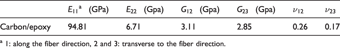
a 1: along the fiber direction, 2 and 3: transverse to the fiber direction.
Since the braid angle is not equal over the non-circular cross-section, the braid angle in each material points of NACA 23018 is required to gain the stiffness matrix of each point. In this regard, the variation of braid angles over the NACA 23018 profile was obtained from the proposed theoretical model [33]. A VUMAT subroutine script was written based on derived relations which calculates the stiffness matrix of each point by calling the predicted braid angles as inputs. Then, to simulate the exact condition of four-point bending test in ABAQUS, the four-point bending loading configuration was modeled as rigid half cylinders (analytical rigid) with the length and diameter of 130 mm and 45 mm, respectively. A three-dimensional deformable part with the cross-section shape of NACA 23018 was designed. Then, through implementing the VUMAT subroutine, the stiffness matrix of each point is calculated and assigned to the defined sections on NACA 23018 part. After assigning the elastic properties of each point, all parts were placed on their exact location, the same as experimental procedure (Figure 6). A penalty based surface contact was defined between the surfaces with the friction coefficient of 0.1. Based on the observations during the four-point bending test, no apparent slippage occurred between the sample and fixture. However, based on the published studies, a friction coefficient (0.1) was considered in the simulation to avoid slippage. The displacement and rotational degrees of freedom of supporting cylinders were fixed and the applied displacement on the loading cylinders was 40 mm along the Y-direction. Composite part was discretized through seeding four elements along the thickness direction and generating a total number of 8640 meshes (average mesh size of 0.8 mm) using C3D8R element type. The ABAQUS explicit solver was employed to perform the MSFE model.

The assembly of simulated braided composite sample with NACA-23018 cross-section under four-point bending.
Results and discussion
In following, the experimental results obtained for biaxially and triaxially braided composite samples are reported and compared. Then, the MSFE modeling results are discussed and compared to experimental ones.
From the results of the four-point bending test, which were recorded as bending force-deflection curves, the stiffness (
Comparing the results obtained from experimental and MSFE modeling.

The elastic regions of bending force-deflection diagrams obtained by the experimental procedure and also predicted by the MSFE modeling are shown in Figure 7. Bending responses were plotted until the onset of non-linear manner due to matrix cracking. A good agreement between the diagrams obtained by the experimental and MSFE modeling approaches can be seen in the elastic region. The verification of MSFE modeling in the elastic region by experimental values confirms the accuracy of the proposed MSFE modeling [34] in predicting the elastic constants of braided NACA 23018 composite.

Force-deflection curves obtained from experimental and MSFE modeling for (a) biaxially and (b) triaxially braided NACA 23018 composite.
As mentioned earlier, the material stiffness matrix alters from point to point over the braided NACA 23018 airfoil composite due to the inequality of the braid angles. The braid angles variation predicted by the proposed theoretical modeling [33], the same as shown in Figure 5, which were being used by the MSFE modeling as inputs are shown in Figure 8. One can notice the equality of braid angle along the longitudinal direction due to the consistency of cross-section geometry along the length of sample.

Variation of braid angle around the cross-section of braided NACA 23018 composite samples.
The von Mises stress distribution in biaxially and triaxially braided NACA 23018 composite is shown in Figure 9. In addition, the deformed braided NACA 23018 composite sample under four-point bending loading observed in the experimental procedure and obtained in the MSFE modeling are shown in Figure 10. In overall, based on the findings herein, blade skins with the shape of airfoil were successfully fabricated (biaxially and triaxially) using a circular braiding machine. The triaxially braided airfoil composite part exhibited superior performance over the biaxially counterpart. In addition, a verified MSFE modeling was implemented to predict the elastic response of fabricated airfoil composite samples. The obtained results agreeably conformed to the experimental data.

von Mises stress contour for (a) biaxially and (b) triaxially braided NACA 23018 composites.

The deformation of braided composite airfoil under four point bending, (a) FE analysis and (b) experimental.
Conclusion
The main goal of the current study was to fabricate a carbon/epoxy airfoil composite skin circular braiding machine for employing as blade skin. To this end, appropriate wooden mandrels with the cross-sectional shape of NACA 23018 airfoil were manufactured. In further, the mandrels were braided biaxially and triaxially to obtain a uniform braided preform followed by epoxy resin impregnation using a suitable fabrication approach. After curing the carbon fiber reinforced composite airfoil skin, four-point bending test was carried out on fabricated samples. Test results indicated the superior performance of triaxially braided composite airfoils over the biaxially braided ones. This was due to the presence of axial carbon rovings in longitudinal direction. In addition, a validated meso-scale finite element modeling was utilized to predict the elastic response of composite airfoils under four-point bending loading. In this regard, the braid angle variation over the NACA 23018 airfoil is required to predict the stiffness constants of each segment. It is noteworthy that the angle braid variation is caused by the alteration of radii of curvature. Thus, a validated theoretical model was employed to predict the braid angle in each segment of NACA 23018 airfoil cross-section. Finally, the predicted bending load-deflection in elastic region was acceptably in agreement with the experimental results.
Footnotes
Declaration of conflicting interests
The author(s) declared no potential conflicts of interest with respect to the research, authorship, and/or publication of this article.
Funding
The author(s) received no financial support for the research, authorship, and/or publication of this article.