
Abstract
PET (Polyethylene Terephthalate) fabric, as one of the airbag materials, has good viscoelasticity and permeability. The surface treatment of airbag fabrics often comes in two types (coated and uncoated) depending on their type and cost. In this study, two fabrics of the automobile airbag material PET was used in the presence and absence of surface coating with PVC (polyvinyl chloride). Three different types of experimental tests including off-axial uniaxial tension, biaxial cyclic loading and picture-frame shear cyclic loading were used depending on the fabric’s load state during the airbag inflatable deployment and folding process. The two materials’ uniaxial tensile modulus and the biaxial tensile modulus were successfully obtained. According to the experimental results of the two materials, the coated material was found to have superior elastic properties than the uncoated material. However, the stress-strain change path was consistent, allowing for a more accurate definition of the material properties of automobile airbag fabric and stronger technical support for the development of automobile airbag safety.
Keywords
Introduction
As an important part of the passive safety system for the protection of automobile occupants, automobile airbag has become a vital safety component required by national laws to be installed by automobile manufacturers. The accurate characteristic state of the airbag, when it is folded and deployed, must be obtained during the early research and development process of the vehicle in order to verify the protection capability of the airbag. Therefore, it is necessary to accurately evaluate the performance of the airbag fabric material, so as to apply it to the early research and development process of the vehicle. At present, as a kind of woven products, many researchers have conducted a lot of in-depth research on similar woven fabrics and their structural products, and have achieved relatively fruitful results.
Some researchers used the uniaxial tensile test to analyze the material properties of woven fabrics since it can easily reflect numerous material characteristics. Penava et al. investigated Young’s moduli of different fabrics in seven angles and reported maximum elastic moduli in warp and weft directions with minimum value in the 45° direction. 1 Ambroziak et al 2 reported technical testing methods of different woven fabrics and represented the results of these tests. Ambroziak et al. presented a method of laboratory tests and concluded that it was necessary to assess the influence of temperature on the mechanical properties of polyvinylidene fluoride-coated polyester fabric in order to identify the mechanical properties of coated fabric.3,4 Raftenberg and Mulkern 5 investigated single-ply specimens of plain-woven Kevlar KM2 fabric using uniaxial tension tests and established the fabric stress-crosshead displacement curve by the least-square-error fits method. Hu et al6 –8 performed numerical simulation and uniaxial tensile tests using the triaxial tensile machine for a three-dimensional membrane composite.
Colman et al 9 designed a novel picture frame shear test and reported its associated test protocol that intended to provide a practical solution for the accurate determination of the in-situ shear stiffness of architectural fabrics. Chen et al 10 presented a new test method to determine the shear properties of architectural coated fabric. It relied on the biaxial pretension of cruciform specimens where warp and weft yarns are oriented at 45° with respect to the loading directions while developing an advanced biaxial tensile test system to implement biaxial loading by either displacement or force control strategy. Xu et al 11 investigated the off-axis mechanical behaviors, ratcheting behaviors and strain decomposition of PVC-coated fabrics under cyclic loading with different off-axis angles, stress amplitude and loading rate. Shi et al 12 employed two approaches to investigate the shear stress-strain characteristics and to understand the shear properties of two typical architectural coated fabrics, that is, PVDF-coated polyester fabrics and PTFE-coated glass-fiber fabrics.
Due to the interaction between warp and weft yarns in two-dimensional woven fabrics, it is essential to define biaxial mechanical properties despite them being more complex in terms of equipment, specimen and test methods compared to uniaxial ones. To characterize the nonlinear anisotropic material properties under large shear deformation and to obtain the difference between neat and silica nanoparticle-impregnated fabrics, Dong et al 13 performed and compared uniaxial and off-axis tensile tests on five styles of Kevlar fabrics. Chen et al 14 investigated the envelope fabric Uretek321A under both uniaxial and biaxial tests and reported the tensile properties. Ansell et al 15 presented a different structure of several commercial PTFE-coated fabric systems and compared their performances by using mechanical testing, scanning electron microscopy and weathering in artificial and natural environments. Glaser and Caccese16,17 presented an experimental method and obtained the mechanical properties including tensile strength, stiffness, and shear properties of orthotropic polyurethane-coated nylon fabric. Mott et al 18 developed an experimental method and encoded software to effectively evaluate the material behavior characteristic of coated glass fabrics for applications in large roof structures. Guitton et al 19 carried out novel multiaxial loading tests for investigating the mechanical behavior of polymers. Reinhardt 20 investigated polyester fabrics coated with PVC and discovered that both the biaxial and uniaxial tensile strength outcomes were equal. Shi et al 21 performed biaxial tensile tests to investigate the material behavior of architectural fabric membranes.
Automotive safety airbag fabrics are generally divided into two categories (coated and uncoated) based on vehicle models and cost differences. This is different from the application scenarios of previous fabric research objects such as aerospace high-strength fabrics and construction engineering fabrics. Considering the current application status of airbag products, there are adhesive-coated materials with good elasticity but poor breathability. To comprehensively obtain the accurate characteristic state of an airbag deployment, it is necessary to accurately evaluate the mechanical properties, compare the mechanical properties of materials with or without coatings and verify the protective effect of car airbags on passengers’ body.
Considering previous research results and evaluation of the mechanical properties of the airbag material PA66, this study considered two types of materials as the research objects formed by the common airbag fabric PET coated/uncoated PVC material. Based on the application scenarios of airbag fabric materials and the characteristics of multiple folding and unfolding, three fabric experiments including multi-angle uniaxial tension, biaxial tension cyclic loading and picture-frame shear cyclic loading were conducted. The mechanical behavior (elastic modulus, stress-strain relationship curves) of the two fabric materials under three experimental conditions was obtained. The accurate performance of automotive airbag fabric materials was defined while providing strong technical support for the development of automotive airbag safety.
Experimentation
Materials and specimens
In this study, conventional PET material (Polyethylene Terephthalate) was conducted using a plain weave of 7 × 7 yarns (per linear millimeter in weft and warp) for the automobile airbag fabric experiment. Two types of experimental materials were used depending on whether the coating material PVC (polyvinyl chloride) was added to the surface or not. Due to the high material manufacturing level, there was relatively uniform rectangle in the woven fabric cross-section in the manufacturing process. The thickness of the coated material was 0.42 mm and the density parameter (plane density) was 438 g/m2. The corresponding parameters of the uncoated material were 0.34 mm and 357 g/m2, respectively. As known, airbags are multiply folded and deployed while impacting occurrence, which is similar to the process of cyclic loading state. In this study, two cyclic loading methods were developed based on the specifications of MSAJ and ISO fabric standards.22,23 The detailed loading processes and fabric experiments are presented in Table 1.
Test materials and load conditions.

Uniaxial tension test
The specimen sample was a strip with 300 mm length, 50 mm width, and 200 mm gage length. As shown in Figure 1(a), the strip was obtained by cutting the samples with off-axis angles of 0°, 30°, 45°, 60°, and 90° from the warp direction to analyze the tensile properties of different fiber angles. To ensure the integrity of the middle fibers, 5 mm wide fiber filaments were removed from both sides of the sample in contrast to the laser cutting fabric scheme in the shear and the biaxial tensile experiment. The sample fabric was divided into a 10 mm by 10 mm grid to facilitate deformation observation during the stretching process (Figure 1(b)). The uniaxial tensile test was conducted on a 100 KN ZWICK testing machine. A special fixture with wave shape was designed for sample clamping, where one M8 screw was tightened to each end of the fixture to ensure uniform pressure and prevent any fabric slippage (Figure 1(c)). Moreover, a 1 mm thick EPDM rubber pad was added to the upper and lower sides of the fabric. When the bolts were tightened, the fabric got tightly fixed without lateral sliding or stress concentration.

Diagrams with off-axis dimensions of the uniaxial specimen: (a) picture of uniaxial specimen with off-axis dimension, (b) schematic diagram of uniaxial test grip, and (c) schematic diagram of uniaxial test setup.
In this study, three sets of experiments including a tensile test, single cyclic loading and four cyclic loading were designed. The three sets of tensile experiment processes were as follows:
The first test type was to break the specimen at a loading speed of 100 mm/min. The force-displacement curves during the loading processes were recorded. When the loading speed was 100 mm/min, the second cycle recorded a loading displacement of 40 mm while reaching an elongation of 20%. It returned to the initial position at the same speed (Figure 2). The third type of four cycles, which has a loading speed of 100 mm/min, sequentially loaded and unloaded displacement of 10, 20, 30, and 40 mm and unloaded displacement to zero in each cycle (Figure 2). According to the method recommended by the Membrane Structures Association of Japan (MSAJ 2003),22,23 the test temperature was 23 ± 2°C and the relative humidity was 65% ± 3%.

Loading processes of uniaxial tension test.
Picture-frame shear test
Similar to the uniaxial test, the picture-frame shear experiment was also completed on the testing equipment ZWICK Z100. The size of the shear specimen frame designed in this project was the same as that of the biaxial tensile experiment (Figure 3 and Wang et al 24 ), except having 10 mm by 10 mm grid lines in the deformation area to facilitate displaying the deformation characteristics of the fabric. However, the experiment was a frame shear process. The schematic diagram of the picture frame is shown in Figure 4. The picture frame consists of five basic parts including a shaft, clamping plate, rubber pad, multiplier hinges, a long plate with a slot and crosshead mounts for connecting the top and bottom hydraulic grips. The frame length and fabric application length are 100 and 80 mm, respectively. As shown in Figure 4(b), each constraint quadrant is designed with a wavy tooth pattern pressure block similar to the fixture used in the uniaxial tensile experiment, which is fixed and clamped with three M8 bolts. The four quadrants are interactively connected by hinges.
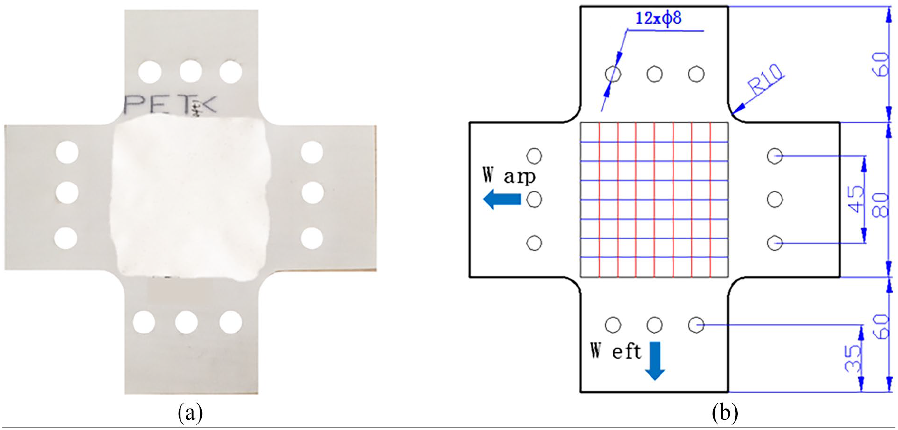
Picture-frame shear specimen (a) before test and (b) diagram with dimensions.

Schematic diagram of picture-frame shear test setup: (a) schematic diagram of grip end assembly with specimen, (b) cross section of clamping plate, and (c) schematic diagram of gage.
According to the experimental specifications,22,23 two loading methods were defined for the picture-frame shear experiment. The first method was intended to tensile 20 mm displacement at a rate of 5 mm/min after preloading with a displacement of 0.5 mm during the experimental process, and then unload to the initial position at the same rate (Figure 5(a)). Under the second loading condition, the specimen was stretched for 20 mm at a tensile rate of 5 mm/min and unloaded to the initial position at the same rate while completing the first loading cycle. The specimen was then stretched for 40 mm displacement at the tensile rate of 5 mm/min and unloaded to the initial position at the same rate while completing the double cycle loading test (Figure 5(b)).
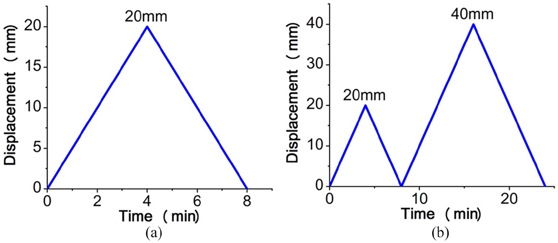
Loading processes of picture-frame shear test: (a) single cycle loading process, (b) double cycle loading process.
Biaxial tension test
According to the test standard for airbag fabric, the PET fabric in this study was also required to complete the biaxial tensile test including single-cycle and double-cycle experiments. We did not include an in-depth discussion in this paper as the biaxial tensile test process, experimental equipment and sample size as shown in Figure 3 were described in detail in the published research paper. 24 Corresponding experimental results are included in the discussion part of this paper.
Results and discussion
Uniaxial tensile behavior
The fabric tensile process is approximately equivalent to a plane stress state. The tensile stress and strain can be directly calculated using the following definitions of tensile stress and logarithmic strain.


Where the term
Because PET fabrics’ cyclic loading curves clearly exhibited nonlinear characteristics, a reference method was used to obtain elastic modulus, which reflected the material’s deformation resistance ability. The loading and unloading curves for each cycle were evenly divided into several parts. Every part was considered as linearity and the secant slope was obtained by the least square fitting method. As shown in Shi et al., 12 the elastic modulus was equal to the average slope of each part.
The elastic modulus of the loading was largest in the 0° direction, followed by the 90° direction and finally the 60°, 30°, and 45° directions (Table 2 and Figures 6, 7). This was mainly related to the weave structure of PVC-coated fabrics. As the crimp levels in the warp and weft directions were not identical, the yarn in the 0° direction had the largest stiffness. Moreover, as the yarn was mainly subjected to shear stress in the 45° direction, the stiffness was the smallest. During material fracture testing, the tensile strength of coated PET fabric in the 0° direction reached 22.58 MPa, while it was only 20.84 MPa in the 90° direction. However, the tensile strength of uncoated PET fabric in both directions was slightly smaller (19.76 and 18.37 MPa).
Summary of uniaxial tensile properties of tested fabric.


Young’s modules at single cycle loading process

Tensile strength at single cycle loading process.
Under single cycle loading, for coated fabric materials, there is 10/20 MPa in the warp/weft direction at 0°/90° respectively. The fabric material performance decreased by about 20% at a 30°/60° angle. However, the tensile strength was the smallest (3 MPa) at 45°. The stress was small for uncoated PET fabric materials. This was because the material could not have entire fibers for deformation resistance under 45° cutting conditions. The PET fabric retained fibers to resist deformation at 30°/60° conditions.
The material loading force slightly decreased due to the creep characteristics exhibited by the woven fabrics under four loading conditions (Figure 8). However, due to the same loading path and displacement, the PVC coating material has a weak protection effect on the woven fabric, resulting in little impact on the four-cycle loading results.

Stress-strain curves in warp and weft directions under different loading cycles: (a) coated fabric, single cycle in warp direction, (b) coated fabric, single cycle in weft direction, (c) coated fabric, four cycles in warp direction, (d) coated fabric, four cycles in weft direction, (e) uncoated fabric, single cycle in warp direction, (f) uncoated fabric, single cycle in weft direction, (g) uncoated fabric, four cycles in warp direction, and (h) uncoated fabric, four cycles in weft direction.
Picture-shear behavior
Due to the special woven structure of PET fabric, there was a significant difference between metals or other homogeneous sheets in material shear response behavior. The two yarn families in warp and weft directions rotated relatively having shear behavior, which resulted in the in-plane shear material behavior during the in-plane shear test process (Figure 9). The grid pattern printed on the cruciform specimen was measured and obvious deformation characteristics were monitored. At this stage, the yarn families were orthogonal to one another and had undergone fairly uniform shear deformation in center areas and shear stress concentration in four corner positions during DIC (Digital Image Correlation) testing (Figure 10).

Deformation process of picture-shear test setup assembling specimen.

Strain distributions at loading peak obtained by DIC: (a) fabric coated single cycle, (b) fabric coated double cycles at first loading peak, (c) fabric coated double cycles at second loading peak, (d) fabric uncoated single cycle, (e) fabric uncoated double cycles at first loading peak, and (f) fabric uncoated double cycles at second loading peak.
Based on the deformation process of the hinge frame during the frame shear experiment, the shear strain and shear stress were defined. Detailed explanations were shown in Figure 11. When the quadrilateral shape of the hinge frame was stretched and deformed, the four edges of the picture frame were constrained by hinges and underwent induced deformation.
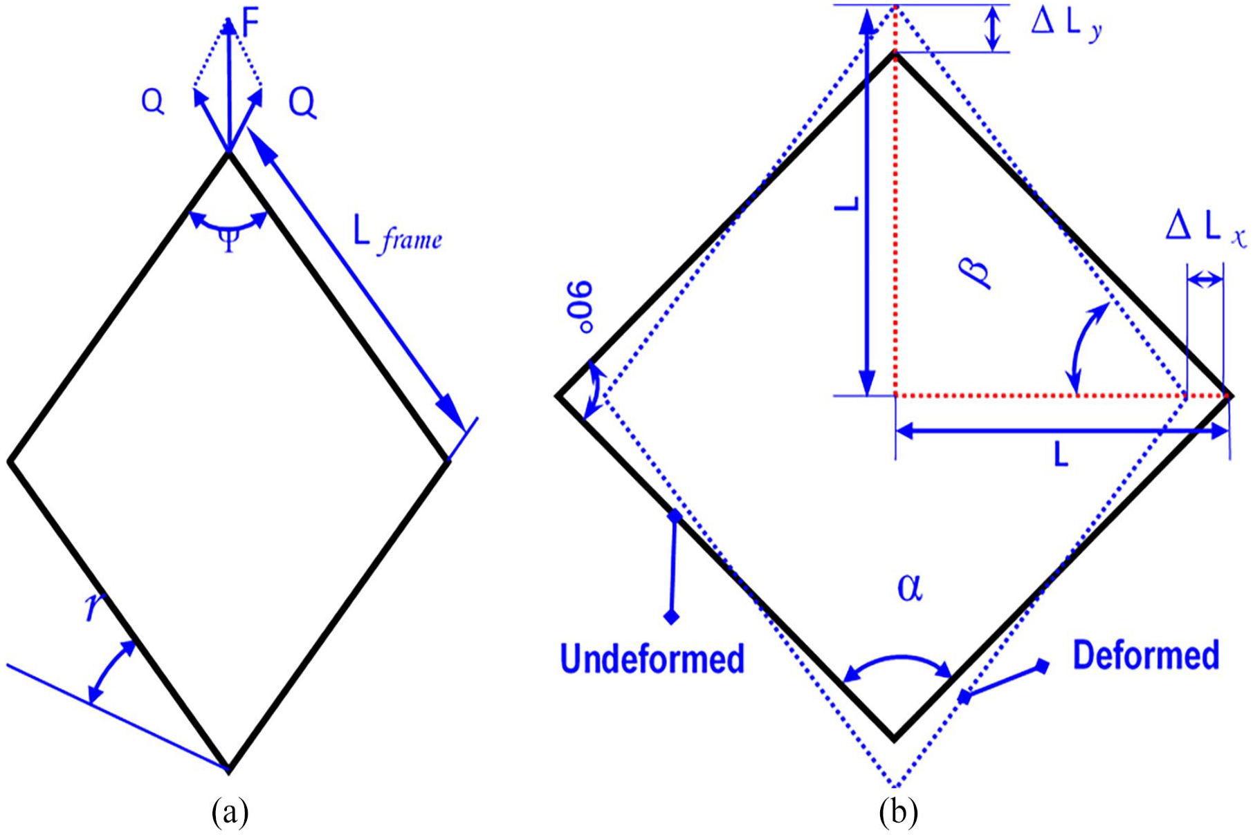
Frame deformation mechanism: (a) loading force decomposition of frame, and (b) schematic diagram of shear strain.
Therefore, shear force

Where

r : complementary angle of the shear angle.
Furthermore, shear stress can be directly calculated from shear force as:

As shown in Figure 13, based on the trigonometric function relationship of the mirror frame, it was easy to obtain the following angle relationship.


Where, d is displacement (longitudinal) and


Where, t is the thickness of fabric material.
Considering the experimental results and the previous calculation process of shear stress, the shear stress of coated and uncoated fabrics can be calculated as shown in Table 3 and Figures 12 and 13, where the two peak shear stresses of the double cycles can also be figured out. The maximum shear stresses were 3.42 and 3.25 MPa for the coated and uncoated fabrics under the single-cycle picture-shear loading method, respectively. However, under the double-cycle picture-shear loading method, the corresponding maximum shear stresses were 3.47 and 3.22 MPa, respectively.
Summary of shear properties of tested fabrics.


Shear stress-shear strain curves under different loading cycles: (a) coated fabric, single cycle, (b) uncoated fabric, single cycle, (c) coated fabric, double cycles, and (d) uncoated fabric, double cycle.

Shear strain-loading force curves under different loading cycles: (a) coated fabric, single cycle, (b) uncoated fabric, single cycle, (c) coated fabric, double cycles, and (d) uncoated fabric, double cycle.
The occurrence of shear deformation of the fabrics observed in the experiments was mainly due to the resistance of the yarn to rotation, bending, shearing, and compaction at the intersection. The observed increase in shear stress was probably due to the increase in rotational friction at the yarn intersection, resulting in the increase in yarn tension and out-of-plane contact force. These changes can also be clearly seen from the shear stress-shear strain curves (Figures 12 and 13).
Biaxial tensile behavior
The strain distributions from DIC observation results in terms of warp and weft directions same to real tensile coordinate system were as shown in Figure 14.

Strain distributions at peak load according to DIC testing: (a) coated fabric, single cycle, (b) coated fabric, double cycle at first loading peak, (c) coated fabric, double cycle at second loading peak, (d) uncoated fabric, single cycle, (e) uncoated fabric, double cycle at first loading peak, and (f) uncoated fabric, double cycle at second loading peak.
The maximum strains occurred at the fillet position and decreased toward the center similar to the deformation behavior of PA66 material. There was no obvious difference between the strain distribution and failure state of the two types of fabrics under the same loading condition as the loading was displacement. Obvious damage occurred at the fillet positions of the specimen after the second cycle loading.
For a plane stress orthotropic model, Poisson’s ratios,


Where the term
The biaxial tensile experiments listed in Table 1 were performed. The experimental results expressed in MPa were shown in Table 4 and Figure 15.
Summary of biaxial tensile properties of tested fabrics.


Stress-strain curves in warp and weft directions under different loading cycles: (a) coated fabric, single cycle in warp direction, (b) coated fabric, single cycle in weft direction, (c) coated fabric, double cycle in warp direction, (d) coated fabric, double cycle in weft direction, (e) uncoated fabric, single cycle in warp direction, (f) uncoated fabric, single cycle in weft direction, (g) uncoated fabric, double cycle in warp direction, and (h) uncoated fabric, double cycle in weft direction.
Considering the experimental results, the detailed experimental values of PET fabrics were found to be different from PA66 fabrics. The maximum stresses were 34.4 and 45.2 MPa, at the warp and weft directions. The coated fabrics were deformed by 7 mm under the single cycle loading method. However, under the second cycle of the double-loading method, the corresponding maximum stresses were 36.7 and 46.4 MPa, respectively. For uncoated fabrics, the maximum stresses were 35.8 and 50.4 MPa, respectively, in two directions under the single-cycle loading method after warp and weft were deformed by 7 mm. The maximum stresses under the second cycle of double cycles loading method were 38.2 and 58.3 MPa, respectively. The difference in tested parameters between the two types of fabric materials was due to their application in different vehicle conditions based on the product specifications.
Conclusion
In this paper, the tests including the uniaxial tension test, biaxial tension test and picture-frame shear test of PET-uncoated/ coated PVC fabrics were investigated. The following useful conclusions can be drawn:
(1) As a common type of automotive airbag material, PET material was assembled after going through multiple folds. Based on the characteristics of the layer-by-layer deployment process after being triggered, three tension experiments including biaxial tension testing, uniaxial tension testing and picture-frame shear testing were designed to comprehensively evaluate the characteristics of PET fabric during the airbag folding and deployment process.
(2) Considering uniaxial tension testing and biaxial tension testing, although PET fabrics either coated or not was relatively weaker than PA fabric used as airbags material, they can be used in protective airbags for legs and shoulders.
(3) Two types of PET airbag fabrics were used (uncoated/ coated with PVC) in three testing methods. According to the experimental results, there were a few obvious differences in the shapes of the stress-strain curves of each fabric in the warp and weft directions. The elastic properties of the coated fabric were better than those of uncoated fabric. The comparative results of these tests could help automotive engineers improve their application in airbag fabrics.
Footnotes
Acknowledgements
The authors are grateful to the editors and anonymous reviewers for professional comments and suggestions in improving the quality of the paper.
Data statement
Only part of the data, models, or code generated or used during this study can be shared at present due to the ongoing projects.
Declaration of conflicting interests
The author(s) declared no potential conflicts of interest with respect to the research, authorship, and/or publication of this article.
Funding
The author(s) received no financial support for the research, authorship, and/or publication of this article.