
Abstract
Separating fabrics stack using mechanical devices is considered a major obstacle to automation in garment processing due to their low density, low bending stiffness, and air permeability. To address this challenge, this paper discusses the feasibility of using a non-contact Bernoulli suction cup for automated separation and transfer of fabrics stack. First, a theoretical analysis of the non-contact separation mechanism was carried out and a calculation model for the separation process parameters was proposed. Subsequently, based on the calculation model, to improve the success rate of separation, a novel gradual descent separation method was proposed by analyzing the variations of suction force of Bernoulli suction cup with process parameters. To address the problem of fabric instability and falling during non-contact transfer, a visual control method that uses machine vision technology to regulate the suction force was also introduced. Finally, the above methods were integrated to create a non-contact automatic fabrics stack separation and transfer system. The results show the following: (1) The deviation between the results of the calculation model and the measured results is 6.9%; (2) The success rate of stack separation using the gradual descent method is 96%; (3) The improved visual detector achieved a recognition accuracy of 0.982 for the sagging deformation of the fabric piece. The visual control suction method can stabilize the fabric within 300 ms at a transfer speed of 800–1000 mm/s. The method for non-contact automatic separation and transfer of fabrics stack proposed in this paper provides new ideas for related research and industrial applications.
Introduction
As the traditional garment industry modernizes and transforms, cutting and sewing processes have reached a high level of automation. However, there are still bottlenecks in the automatic separation of fabrics stack, which serve as the basic technology for automated assembly lines in the garment industry. Fabrics are characterized by properties such as low density, low thickness, low bending stiffness and air permeability that make them difficult for traditional mechanical gripper to grasp.
Currently, fabric grasping methods can be categorized into contact-based and non-contact-based methods. The classification and typical examples of fabric grabbing techniques are shown in Figure 1.

Fabric grasping methods. (a) Electrostatic adsorption. (b) End effector of Potier effect. (c) Vacuum chuck. (d) Needle punched end effector. (e) Polymer bonded end effector. (f) Mechanical gripper. (g) Bernoulli suction cup. (h) Vortex suction cup.
Contact-based methods include physical adhesion,1–3 interlocking with a medium,4,5 and mechanical clamping.6,7 A hot research topic is the use of soft grippers to grab fabrics. This type of gripper is mostly a biomimetic structure with two fingers arranged opposite to each other, and it grasps the fabric by imitating the pinching action of human fingers. This structural material is mainly made of rubber, so the gripping force comes from the frictional force between the gripper and the fabric. Of particular interest is the work by Su et al.,8,9 who designed two bio-inspired pneumatic flexible grippers. By mimicking the pinching action of human fingers, they achieved fabrics stack separation. 10 Contact-based grasping methods offer high stability but can cause damage to the fabric. For example, mechanical clamping can result in macroscopic creases. Needle-based actuators can compress or even puncture the fibers when penetrating the fabric. Physical adhesion and medium-based methods can lead to electrostatic contamination and residual compounds on the fabric surface.
Non-contact grasping methods exhibit advantages such as strong adaptability, simplicity of equipment, absence of marks on the handled material’s surface. Thus, they are suitable for applications that require high surface quality or medical hygiene standards, such as the handling of semiconductor wafers, food items, and surgical devices. Non-contact-based methods include Bernoulli-based and vortex-based approaches.11–13 Bernoulli suction cup, as a typical non-contact grasping actuator, has gained significant attention from researchers worldwide. In the field of semiconductor manufacturing, Li 14 and Brun and Melkote 15 have investigated the pressure distribution and suction force of Bernoulli suction cup grasping silicon wafers through theoretical analysis and experimentation. Liu et al. 16 has achieved non-contact handling of ultra-thin silicon wafers using Bernoulli suction cup. In the food processing field, Rawal 17 and Davis et al. 18 have discussed the feasibility of using Bernoulli suction cup for handling cookies or sliced fruits and vegetables. In medical applications, Ertürk and Erzincanlı19,20 studied four different type of Bernoulli suction cups and compared their performance under different airflow rates. They found that Bernoulli suction cup can stably and flexibly handle and transfer animal organs like chicken hearts without causing damage to the organ tissues. Moreover, Bernoulli suction cups have also been applied in non-contact handling of objects such as off-center antenna trays 21 and battery electrodes. 22 The aforementioned studies primarily focused on handling structurally dense, semi-rigid, or rigid objects, and therefore, the theoretical models and implementation methods may not be directly applicable to the handling of breathable and flexible fabric pieces in the apparel manufacturing field.
Non-contact suction of fabrics presents key theoretical and technical challenges, including difficulties in cut pieces stack separation and unstable transfer. Ozcelik and Erzincanli 23 investigated the feasibility of using Bernoulli suction cup for grasping and transferring fabric pieces. They found that setting a conical deflector at the nozzle of the suction cup can change the airflow direction and weaken the impact force of high-speed airflow on the fabric, thereby improving fabric suction stability. Additionally, they conducted experiments on fabric pieces stack separation. 24 The results showed successful suction of the top layer of the stack, but there was no mention of the separation of subsequent layers. Dini et al. 25 conducted experimental studies on five different configurations of Bernoulli suction cups and found that although the design of the deflector can improve the suction effect, within a certain distance from the lower surface of the suction cup, the suction force on the fabric will exhibit repulsive force, which affects the gripping effect. On this basis, Failli and Dini 26 discussed how to use Bernoulli suction cups to separate the leather stack. They designed an end effector composed of multiple small suction cups and successfully achieved leather stack separation. However, in the experiment, it was found that the leather after being grabbed would naturally deform, and the deformation would weaken the suction force on the fabric, making the transfer process unstable. He et al. 27 constructed a porous medium model for fabric pieces, considering the influence of fabric breathability on suction force and establishing a theoretical model. However, they did not consider the effect of sagging deformation caused by the fabric’s low bending stiffness on suction force, and they did not discuss the issue of stack separation. Therefore, their model still has limitations. Zhang et al. 28 used the ALE fluid structure coupling method to numerically simulate the deformation of fabrics after being grabbed by Bernoulli suction cups, and found that the deformation is related to the number and arrangement position of suction cups. The more suction cups there are, the more evenly arranged they are, and the smaller the degree of deformation. Although the above research has discussed the principle, process model, and application of Bernoulli suction cups for grasping fabrics, the mechanisms and influencing factors of stack separation remain unclear.
This paper addresses the problems of unclear mechanisms for fabrics stack separation, low success rate in stack separation, and insufficient transmission stability in non-contact grasping of fabric pieces. We first propose a calculation model that can accurately predict the required suction force for stack separation. Then, based on the variation of Bernoulli suction cup suction force with process parameters, a gradual descent fabrics stack separation method and a high-speed fabric transfer method were proposed. In addition, machine vision technology is used to detect the sagging deformation of fabric pieces during the separation and transfer processes. Finally, an integrated system was established, creating an automated system for fabrics stack non-contact separation and transfer. This paper provides a new implementation approach for the study and application of automated technologies for separating and transferring pieces of fabric.
The symbol table can be seen in Table 1.
Symbol table.

Mathematical model
Principle and general model
Schematic diagram of Bernoulli suction cup principle is shown in Figure 2(a), where high-speed airflow flows downward along the air chamber passage when the Bernoulli suction cup is in operation. After being obstructed by the conical deflector, the airflow changes direction until it radiates outward from the nozzle along the lower surface of the suction cup, ultimately diffusing into the atmosphere at the edge.
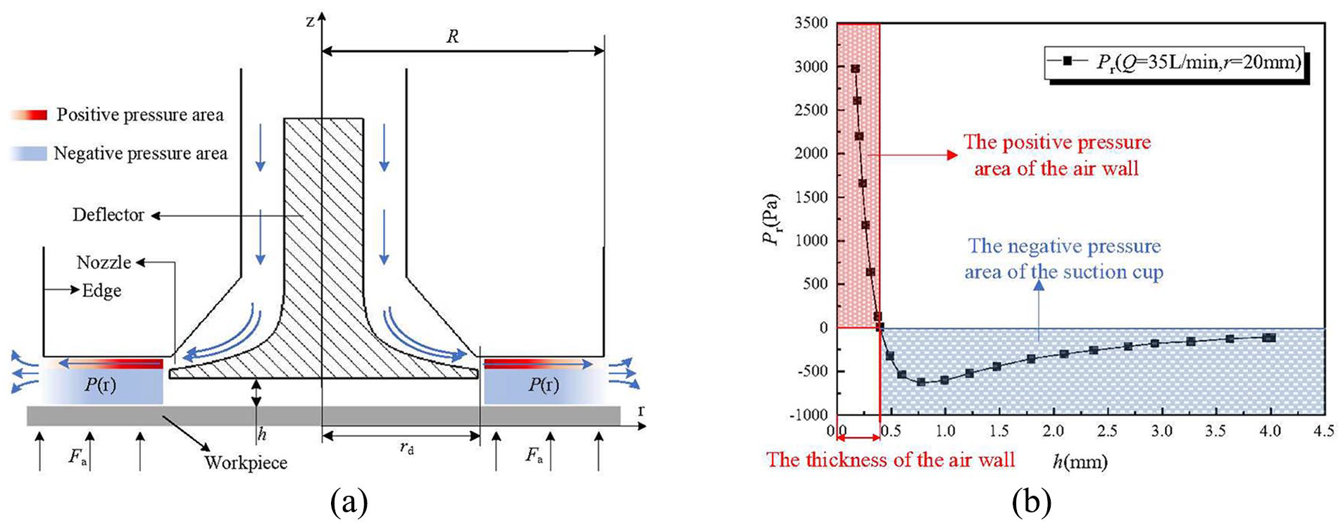
Principle of Bernoulli suction cups. (a) Schematic diagram of Bernoulli suction cup principle. (b) Bernoulli suction cup lower surface pressure variation curve (When Q = 35 L/min and r = 20 mm, h increases from 0 to 4 mm).
According to the Bernoulli principle, the air velocity near the lower surface of the suction cup increases, resulting in a corresponding decrease in pressure, forming a ring-shaped low-pressure zone, denoted as P(r), the blue area in Figure 2(b) is a part of P(r). Meanwhile, the lower surface of the workpiece is still exposed to atmospheric pressure, creating a pressure difference between the upper and lower surfaces. This pressure difference generates a suction force Fa that lifts the workpiece toward the suction cup.
The non-contact grasp of Bernoulli suction cup is realized by an air wall formed on the lower surface of the suction cup. The high-speed airflow sprayed by the suction cup moves along the lower surface of the suction cup, forming a very thin air wall. The positive pressure zone inside the air wall (as shown in the red area in Figure 2(a) and (b)) blocks the workpiece, preventing it from making rigid contact with the lower surface of the suction cup, thereby achieving non-contact grasping.
The general suction model is designed for the grasping of rigid objects. In this case, the pressure field calculation formula is as follows 16 :

The formula for calculating the suction force is presented below 16 :

It can be observed that, with the dimensions of the Bernoulli suction cup structure determined, the suction force mainly depends on two process parameters: the airflow rate Q and the spacing h.
In previous study, 29 we tested the performance of the Bernoulli suction cup, and the layout of the testing platform is shown in Figure 3(a). By adjusting the intake pressure Pi, the intake flow rate Q of the suction cup is adjusted, thereby regulating the suction force Fa. The air path is shown in Figure 3(b). Under the conditions of intake pressures of 0.15, 0.2, and 0.25 MPa, approximately 1800 measurement points were measured below the suction cup, subtracting the pressure values of each measuring point from the atmospheric pressure can obtain the negative pressure value. The layout of the measurement points is shown in Figure 3(c).

Performance testing of Bernoulli suction cup. (a) The layout of the testing platform. (b) The air path of Bernoulli suction cup. (c) The layout of the measurement points.
The measurement results are shown in Figure 4. It was found that the negative pressure area generated by the suction cup is mainly concentrated between the nozzle and the edge of the suction cup, and the maximum negative pressure occurs near the nozzle.

Cloud maps of measurement results of negative pressure distribution on the lower surface of Bernoulli suction cup under different intake pressures. (a) Pi = 0.15 MPa. (b) Pi = 0.2 MPa. (c) Pi = 0.25 MPa.
As the intake pressure increases, the negative pressure area expands accordingly, and at the same time, the average negative pressure increases, indicating an increase in suction force. When the intake pressure is constant, the negative pressure value will decrease with the increase of the spacing h, indicating that the suction force is decreasing.
Due to the softness and breathability of fabric cut pieces, the pressure field of the fabric piece and its relationship with the suction cup change when using a Bernoulli suction cup. In this case, the general model is no longer able to accurately describe the suction force characteristics. Therefore, it is necessary to establish a suction force model suitable for fabric stack separation problem.
Separation suction force calculation model
In this study, the process of separating fabric pieces stack using the Bernoulli suction cup is analyzed, and the main influencing factors are determined as follows:
(1) The atmospheric pressure loss ΔP caused by the breathability of the fabric.
(2) The variation in spacing h caused by the sagging deformation of the fabric, expressed as h (x, y).
(3) The interlayer electrostatic force Fe.
Thus, a pressure field calculation model is constructed, as represented by equation (3). Additionally, a suction force model, as represented by equation (4), is established.


The condition to be satisfied for non-contact layering suction of fabric stack is as follows:

The specific discussion on ΔP, h (x, y), and Fe is as follows:
The atmospheric pressure loss ΔP caused by fabric breathability
The schematic diagram of airflow region division during the suction of breathable fabric by a Bernoulli suction cup is shown in Figure 5. The airflow field can be divided into three distinct regions: the recirculation zone, the gap flow zone, and the upflow zone. The upflow zone is generated by the airflow flowing toward the low-pressure zone due to the pressure difference. The upflow zone is crucial for maintaining the atmospheric pressure environment beneath the fabric. However, during the separating process of fabric pieces stack, this upflow region undergoes pressure losses as due to penetrates through the stack.

The characteristic regions of the airflow field during the grasping of breathable fabric.
To address the above issue, a porous media model for the fabric stack was established, as shown in Figure 6.

Porous media model for fabric stack.
Ergun 30 have found that the pressure loss after the airflow penetrates a porous medium is closely related to the air properties and structural characteristics of the medium. This can be calculated using the following empirical formula:

The expression for ΔP can be obtained by simplifying equation (6):
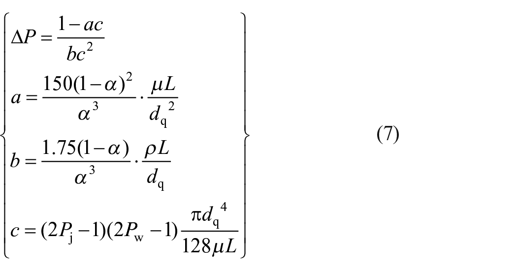
The expression for the equivalent diameter of the flow rate, dq, in equation is as follows 31 :

In the equation: Pj and Pw represent the warp and weft yarn density; dj and dw represent the warp and weft yarn diameter.
Due to the sagging deformation of the fabric, the variation in the spacing h can be expressed as h (x, y)
Fabrics and other flexible materials exhibit a distinct sagging deformation when subjected to non-contact suction, as shown in Figure 7. In this case, the spacing h is not a constant value but varies with coordinates.

Schematic diagram of the sagging deformation of rigid/flexible workpiece subjected to non-contact suction.
To obtain the spacing h between the fabric after sagging and the suction cup, a fabric sagging deformation characteristic analysis model is constructed, namely the deflection surface equation h (x, y). The fabric piece sample is treated as an orthotropic elastic rectangular plate based on the elastic thin plate theory. The deflection surface equation is then solved using the Fourier series expansion method.
Taking the center of the rectangular fabric as the origin, with the warp direction as the x-axis and the weft direction as the y-axis, an orthogonal coordinate system x-o-y is established. According to the elastic thin plate theory, the governing equation can be written as:
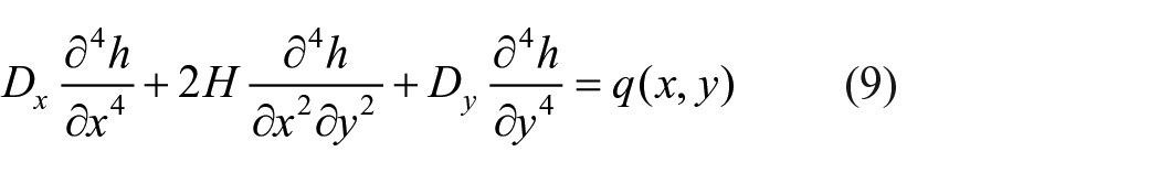
In this equation,
The general solution of the higher-order differential equation (9) is expressed using the deflection surface equation h (x, y), as presented in equation (10), following the approach of utilizing the deflection surface equation h (x, y) as a representation 32 :
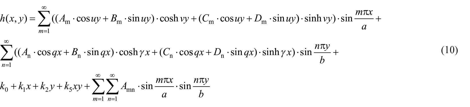
In equation (10), there are undetermined coefficients: Am, An, Bm, Bn, Cm, Cn, Dm, Dn, k0, k1, k2, k5. They can be determined by applying the boundary conditions of the rectangular plate.
The interlayer electrostatic force Fe is taken into consideration
For fabrics made of natural fibers, the separation process can be influenced by interlayer electrostatic force. Assuming that the charge distribution on the contacting surface of adjacent fabric piece is uniform and the charge surface density is constant, the electrostatic force only affects the neighboring two layers of stack. Hence, a fabric stack interlayer electrostatic force analysis model, as shown in Figure 8, is constructed.

Fabric stack interlayer electrostatic force analysis model.
According to Coulomb’s law, the interlayer electrostatic force Fe can be expressed as:

Method
Stack separation and fabric transfer method
When using Bernoulli suction cup for non-contact fabrics stack separation, it is often difficult to continuously separate fabric piece, resulting in a low success rate of separating. Meanwhile, during the subsequent fabric transfer process, due to the suction force being concentrated in the normal direction of the lower surface of the suction cup, the fabric piece is prone to detachment and falling from the side. To solve the above problems, it is necessary to propose stack separation and fabric transfer method.
Stack separation method
In theory, the top object can be successfully sucked when the suction force Fx satisfies the required force for separating the stack. Existing suction methods follow the aforementioned principle by setting the process parameters to their theoretical values. While this method works well when the sucked object is rigid, it still has two major shortcomings: (1) Due to factors such as mechanical equipment errors and losses along the air flow path, the actual suction force fluctuates during practical applications; (2) After the top object is separated, the stack height decreases accordingly, resulting in an increased spacing between the suction cup and the sub-top object, which fails to meet the initially set spacing hx. Therefore, the suction cup height needs to be readjusted after each layer separation, undoubtedly reducing the efficiency. Due to the high sensitivity of soft fabric piece to suction force fluctuations, and considering that the number of fabric layers can reach hundreds, there are high requirements for separation success rate. Hence, the above-mentioned conventional suction methods are no longer applicable.
In order to enhance the success rate of non-contact separation of fabric stack, a gradual-descent stack separation method is proposed based on the analysis of the suction force variation characteristics of the Bernoulli suction cup.
When the airflow rate of the Bernoulli suction cup is fixed, the relationship between the suction force and spacing is shown in Figure 9. As the spacing continues to increase, the suction force exhibits an exponential decrease. Assuming a certain specification of fabric, the theoretical suction force required to successfully separate the top layer from the stack is Fx, corresponding to an airflow rate of Qx and a spacing of hx. The principle of the gradual descent layer separation method is that by setting the airflow rate to Qx and an initial spacing hi slightly larger than hx, the suction cup approaches the top layer of the stack gradually. During this process, there will always be a certain moment when the spacing between the suction cup and the top layer fabric piece becomes hx. The advantage of this method is that it does not require repeated adjustment of spacing before each layering and weakens the impact of suction force fluctuations.

The curve of suction force with spacing when the airflow rate is constant.
The process of gradual descent cannot be indefinitely prolonged. When the suction cup sucks the fabric piece, it needs to stop promptly and then move the fabric piece to the transition point. To achieve these, a visual control suction cup movement method is implemented. The control process of this method is shown in Figure 10.

Flow chart of visual control of suction cup movement.
Fabric transfer method
For lightweight and flexible materials like fabric, the influence of air resistance on their deformation cannot be ignored. During the transfer process, fabric pieces experience air resistance in the opposite direction of their motion. Furthermore, according to the air resistance model (equation (12)), the air resistance force Fd increases correspondingly as the transfer speed increases.

At this point, air resistance gradually detaches the fabric piece from the suction cup in the form of lateral force, leading to the dropping of the fabric piece. This phenomenon severely affects the success rate and efficiency of the transfer process. Figure 11 illustrates the gradual detachment process of the fabric piece sample during the transfer, where the fabric piece transitions from a stable state to an unstable state within 130 ms. Macroscopically, the sagged part of the fabric tilts in the opposite direction of the transfer, and the tilt angle increases as the transfer progresses. The red line indicates the edge of the sagged part of the fabric piece, and the change in the direction and slope of the line reflects the aforementioned process intuitively. The spacing between the fabric piece and the suction cup increases continuously, resulting in a decrease in the suction force. Eventually, the fabric piece detaches and falls off, with a time duration of approximately 380 ms. In the non-contact grasping and transfer process, the interference of external forces is the primary factor affecting fabric stability. Thus, real-time monitoring of the morphological changes during fabric pieces transfer is necessary to enhance fabric stability.

The process of gradual detachment of the fabric piece during high-speed transfer under non-contact suction.
Figure 12 shows several typical inclined unstable deformations exhibited by the sagged part of the lining fabric piece. Even though there are differences in them when the viewing angle remains constant while the angular position of the fabric piece changes, the deformations of the sagged part still possess the characteristic of inclined instability. A dataset is constructed based on these variations to train the object detector.
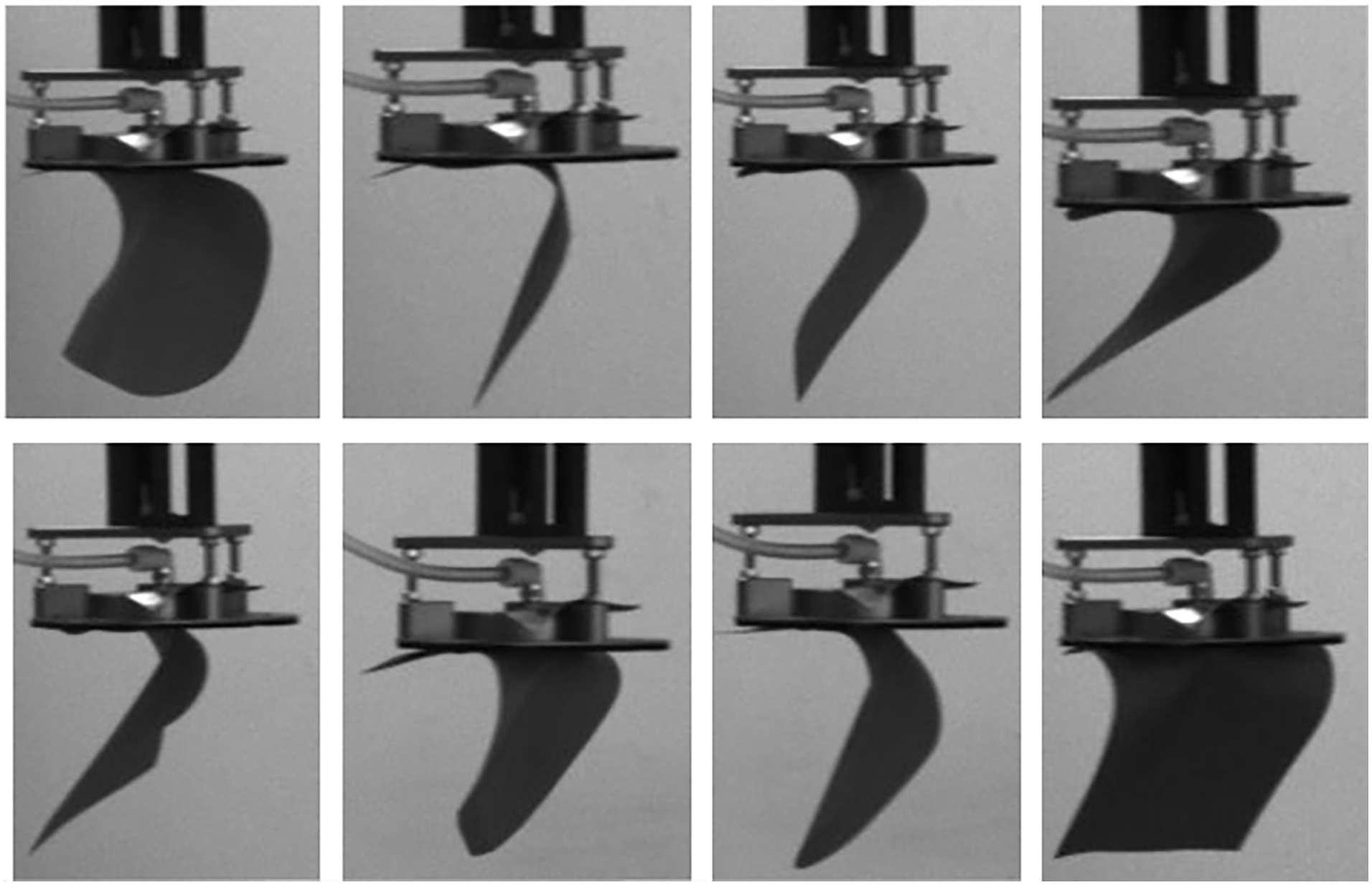
Characteristics of tilting and instability of the sagging part of the pocket lining cut piece.
In order to enhance the stability of the fabric piece during transfer and mitigate the occurrence of the dropping phenomenon, a method utilizing visual recognition information feedback control of the suction cup’s airflow rate is employed to regulate the suction force. The control process of this method is shown in Figure 13.
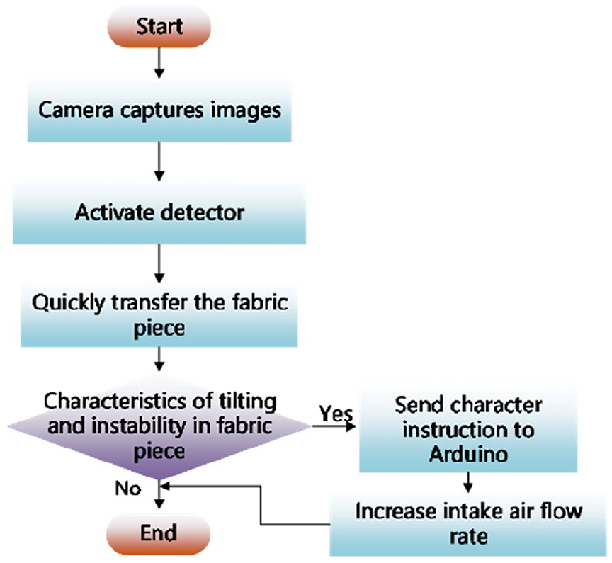
Flow chart of visual control the suction force.
Recognition method for fabric sagging deformation
Due to factors such as flexibility, the deformation of the fabric piece under non-contact suction varies. Additionally, this deformation undergoes dynamic changes during transfer. Therefore, when using machine vision for fabric deformation recognition, challenges often arise, including low recognition accuracy, delayed recognition response, and weak generalization capability. To address these difficulties, this paper discusses the feasibility and necessity of utilizing an improved object detector to identify the deformation of fabric under non-contact suction and transfer.
Improvement of object detector
The YOLOv5s object detector 33 is employed to recognize the sagging deformation of the fabric piece during suction and transfer. To enhance the accuracy of the detector, the ECA (Efficient Channel Attention) mechanism 34 is integrated into the YOLOv5s backbone network architecture (the specific insertion location is illustrated in Figure 14). The fundamental principle and process of the ECA attention mechanism are as follows:
(1) Given an input image X with dimensions C × H × W, where C represents the number of channels, and H and W represent the height and width of the image.
(2) Performing global average pooling on the input feature map, we obtain the vector fi with a dimension of c.

(3) Linear transformation.


YOLOv5s network structure with ECA attention mechanism added to the backbone layer.
Ws and Bs represent the weight matrix and bias vector, respectively, for the linear transformation.
(4) Normalization.

σ represents the sigmoid activation function, which maps si to the range of [0, 1].
(5) Output attention-enhanced feature map.

Xijk and Yijk respectively represent the element values of the input feature map X and the attention-enhanced feature map Y.
Ablation experiment
To evaluate the effect of ECA attention mechanism on improving the accuracy of target detectors, ablation experiments were conducted. We compared the recognition results of the sagging deformation of the fabric piece in three scenarios: initial YOLOv5s, YOLOv5s with CA mechanism, 35 and YOLOv5s with ECA mechanism. The Grad-CAM 36 technology was used to mark the main feature contribution areas of the image during the detection process to explain the detection accuracy, as shown in Figure 15.

The recognition results of the sagging deformation of fabric pieces after adding different attention mechanisms. (a) Original images. (b) The recognition results of the initial YOLOv5s. (c) Results after adding CA attention mechanism. (d) Results after adding ECA attention mechanism.
The results indicate that the addition of attention mechanism can effectively improve the accuracy of the detector, and the ECA mechanism achieves a recognition accuracy of 0.982 for the sagging deformation of the fabric piece.
System integration
The system is mainly composed of the suction system, the suction cup motion system, the machine vision system, and a two-level control system, as shown in Figure 16.

Robot and machine vision collaborative system layout for fabric cut pieces stack separation.
The suction system is responsible for supplying the airflow to the Bernoulli suction cup to meet the suction force requirements. The airflow rate of the Bernoulli suction cup is adjusted by regulating the inlet pressure, thus establishing the pneumatic circuit. The air compressor and air receiver form the air pressure source. The high-pressure gas is conveyed forward after being processed by the F.R.L unit. By using an electrical proportional valve, the inlet pressure is adjusted to the target value. A flowmeter is used to measure the airflow rate.
The suction cup motion system is responsible for enabling flexible movement of the suction cup. To achieve this, a 6-axis collaborative robot is employed, with the end effector having a flange surface on its end face. The suction cup and the robot are connected through a simple bolt connection, facilitating a rigid connection between them and meeting the motion requirements of the suction cup.
The machine vision system consists of four industrial cameras. Camera #1 is positioned directly above the fabric stack, with its optical axis perpendicular to the tabletop of the experimental platform. Camera #2 is located on the left side of the platform, with its optical axis parallel to the tabletop and perpendicular to the optical axis of Camera #1. Camera #3 is positioned below the platform, with its optical axis parallel to the tabletop and perpendicular to the optical axes of Cameras #1 and #2. Camera #4 is placed on the bottom right side of the platform, with its optical axis parallel to the tabletop.
The two-level control system mainly consists of a PC host, an Arduino microcontroller, electromagnetic relays, proportional valves, and a robot controller. The signal transmission paths among them are shown in Figure 17. The PC host is responsible for solving the suction model, running the visual detection algorithms, and sending instructions. The Arduino microcontroller receives instructions and sends digital and analog signals. The remaining devices are responsible for task execution. The signal transmission within the control system is divided into four paths:
(1) The red path represents the acquisition of fabric piece suction position information by the camera #1, which is then sent to the PC through IP communication. After processing, the PC sends the information to the robotic arm controller. The controller drives the robotic arm to move the suction cup to the suction position by executing the corresponding instructions, thereby achieving visual guidance functionality.
(2) The yellow path represents the transmission of the fabric’s sucked and transferred morphology image information from the cameras (camera #2, #3 and #4) to the PC host through IP communication. The target detection algorithm running on the PC host processes the image information and then sends the corresponding character instructions to the Arduino via a serial bus.
(3) The purple path represents the connection between the Arduino and the robotic arm controller through a digital signal interface. Relay is set up in this connection to enable the triggering of corresponding motion instructions in the robotic arm controller when the Arduino receives the character instructions sent by the PC. This implementation allows for the integration of visual information feedback control of the suction cup position.
(4) The green path represents the connection between the Arduino and the proportional valve through an analog signal interface. After receiving the character instructions sent by the PC, the Arduino sends PWM waves with different duty cycles to the proportional valve to regulate the inlet pressure. Consequently, the suction force of the Bernoulli suction cup is controlled, enabling the visual information feedback control of the suction force.

Schematic diagram of signal transmission path of the control system.
The automatic fabric piece grasping system possesses four main functions:
(1) Calculation of the suction separation suction force model;
(2) Visual-guided positioning of the fabric piece for suction;
(3) Visual control the suction cup movement;
(4) Visual control the suction force.
Test and discussion
Validation of the separation suction force calculation model
To validate the calculation model, two sets of experiments are conducted:
(1) The suction force generated by the Bernoulli suction cup at different spacings h (50, 60, and 70 mm) while increasing the airflow rate Q from 32 to 79 L/min;
(2) The suction force generated by the Bernoulli suction cup at different airflow rates Q (80, 150, and 210 L/min) while increasing the spacing h from 15 to 70 mm;
The results of the tests are shown in Figure 18. When the spacing is constant, the suction force gradually increases with the increase in airflow rate. When the airflow rate is constant, the suction force exponentially decreases with the increase in spacing. The average deviation of the theoretical model results from the experimental results is 6.9%.
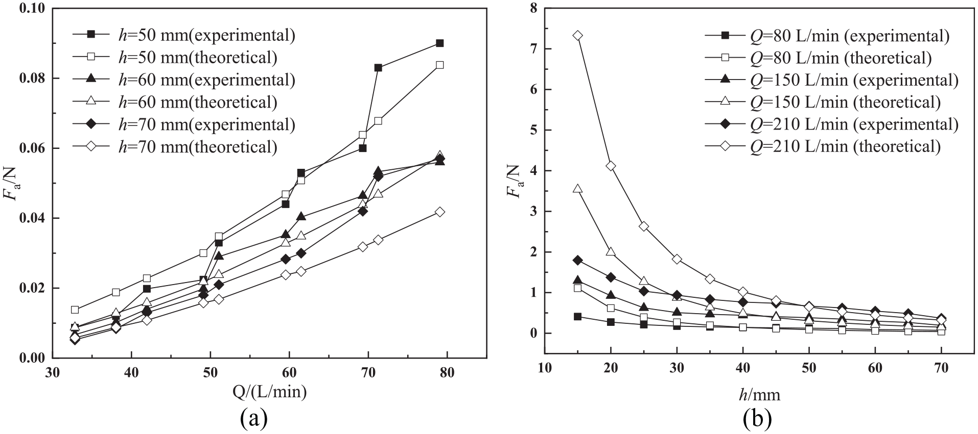
Comparison of suction force test results and calculation model results. (a) The relationship between airflow rate and suction force with constant spacing. (b) The relationship between spacing and suction force with constant airflow rate.
Visual control suction cup movement test
To evaluate the effectiveness of the gradual-descent stack separation method, 10 stack separation tests are conducted. Each test involved performing the separation operation on a stack formed by 10 pocket lining cut pieces.
According to the calculation model, the desired suction force for the pocket lining pieces stack is 0.012 N. The results of the tests can be seen in Table 2, indicating that the success rate of the gradual-descent stack separation method is approximately 96%.
Results of five gradual descent fabric stack separation tests.

★: Single fabric piece is sucked; ☆: Two or more fabric pieces are sucked.
Figure 19 shows the target detection results of the pocket lining cut piece being sucked by the suction cup during the gradual-descent process in Test 1 and Test 2. After the visual signal of the sucked fabric piece is fed back to the robotic arm control terminal, the robotic arm drives the suction cup to transfer the cut piece to the transition point. Figure 20 illustrates the target detection results of the sagging deformation of the fabric piece in Test 1 and Test 2. Based on the above experimental results, it can be observed that the improved target detector achieves an average precision close to 0.98 in recognizing the morphological features of the fabric piece. The visual recognition information can be successfully fed back to the robotic arm control terminal, thereby driving the suction cup.

Camera #2 detected the target of pocket lining piece being sucked by suction cup during the gradual descent process.

Target detection results of sagging deformation of pocket lining piece using camera #3.
Visual control suction force test
To validate the effectiveness of visual control suction force, fabric piece transfer tests are conducted using pocket lining cut pieces as transfer objects. The transfer speed is set at 400, 600, 800, and 1000 mm/s.
The transfer process at different transfer speeds captured by Camera #4 is shown in Figure 21. Figure 21(a) and (b) correspond to the transfer speeds of 400 and 600 mm/s, respectively. It can be observed that when the transfer speed is low, there is no significant tilting of the sagged part of the fabric piece. However, when the transfer speed is increased to 800 mm/s, as shown in Figure 21(c), the target detector identifies the tilting deformation of the sagged fabric piece part within 60 ms and adjusts the suction force within 240 ms, stabilizing the fabric piece. After stabilization, the area of the sagged part of the fabric piece significantly decreases. When the transfer speed is further increased to 1000 mm/s, as shown in Figure 21(d), the tilt of the fabric piece is even greater. The target detector identifies this tilting deformation within 120 ms, and the fabric piece is stabilized within 190 ms.

The transfer process of pocket lining cut pieces at different transfer speed. (Captured by camera #4) (a) Transfer speed is 400 mm/s. (b) Transfer speed is 600 mm/s. (c) Transfer speed is 800 mm/s. (d) Transfer speed is 1000 mm/s.
Based on the above test results, it can be concluded that the visual control suction force method can stabilize the unstable fabric piece during high-speed transfer within a response time of <300 ms, which is shorter than the occurrence time of fabric detachment (380 ms). Moreover, when the transfer speed is sufficiently low to prevent tilting instability of the fabric cut piece, this method does not interfere with the regulation of the suction force.
Conclusions
In order to tackle issues including low success rate of stack separation and inadequate stability of fabric transfer, this paper focuses on exploring the feasibility of using Bernoulli suction cup non-contact grasping technology to separate the fabric stack and transfer the fabric piece. A non-contact separation suction force calculation model is derived, and a high success rate stack separation method and a transfer method are proposed.
The conclusions are as follows:
(1) The average discrepancy between the results of the non-contact separation suction force calculation model and experimental results is 6.9%, accurately reflecting the influence of process parameters on the suction force.
(2) The suction force increases with an increase in air flow rate, but decreases exponentially with an increase in spacing. Based on this observation, a novel gradual-descent stack separation suction method is proposed. Under laboratory conditions, the success rate of the method is approximately 96%. The method can effectively improve the success rate of stack separation.
(3) During fabric transfer, the tilting characteristic of the sagging part of the fabric serves as a key signal for fabric instability. The improved visual detector achieved a recognition accuracy of 0.982 for the sagging deformation of the fabric piece. The proposed method of visual control suction force can rapidly restabilize the fabric piece within 300 ms at a transfer speed of 800–1000 mm/s.
Footnotes
Declaration of conflicting interests
The author(s) declared no potential conflicts of interest with respect to the research, authorship, and/or publication of this article.
Funding
The author(s) disclosed receipt of the following financial support for the research, authorship, and/or publication of this article: This work is supported by the National Key R&D Program of China (Grant No. 2017YFB0309700), Fundamental Research Funds for the Central Universities (Grant No. 223202100062), and Foundation of Key Laboratory of Vibration and Control of Aero-Propulsion System (Grant No. VCAME202104).