
Abstract
The 3D mesh fabric is a key component of automotive seat ventilation systems as it has good compression resistance and creates channels to provide effective circulating airflow. The dimensional inconsistency of fabric sheets by laser cutting to be integrated into car seats and their unrecoverable dimension changes in subsequent cushioning applications are challenging problems. A typical commercialized 3D mesh fabric was observed to shorten and widen under compression, showing an auxetic behavior in the length–thickness section. This counterintuitive partial auxetic behavior accounts for the dimensional variation. A full-size finite element (FE) model of the fabric was established to simulate the complex fabric deformation based on the precise geometry of a unit cell obtained by X-ray micro-computed tomography (μCT) scanning. The FE simulation reproduced the planar dimension change process of the fabric. The underlying mechanism of partial auxeticity was revealed from the global to local analysis, including fabric global deformation, unit meshes deformation and unit cell geometric structure change. It was shown that buckling of initially post-buckled spacer monofilaments drives in-plane movements of monofilament loops to cause partial auxetic behavior. The partial auxeticity weakens in the compression process due to the gradual intercontact and densification of spacer monofilaments. Different constraints on monofilament loops from adjacent unit cells and multifilament inlays make the deformation uneven in the plane of fabric. It is important to fully analyze the dimensional change, especially the partial auxetic deformation, of the 3D mesh fabric under compression for its practical applications.
Keywords
Introduction
Three-dimensional (3D) mesh fabric is an integrated sandwich structure with two separate mesh outer layers linked by coarse monofilament spacer yarns. In recent years, 3D mesh fabrics have found increasing applications in automotive seat ventilation systems due to their tailorable compression resistance and excellent air permeability.1–5 In practice, fabric sheets are normally customized piece by piece via laser cutting from a fabric roll to have required dimensions for different applications. The roll storage fabric is under long-time compression by its own weight and laser cutting is normally conducted immediately after unrolling the fabric. In fact, it has been found that fabric sheets after laser cutting gradually change their planar dimensions with time. It is considered that the dimension change is caused by the internal stress relaxation. The compression load on the fabric is immediately released when it is deployed, but it takes time to release the internal stress and recover its dimension through gradual decompression. The size change can be up to 10%, whereas the dimension change tolerance of fabric sheets accepted by automotive manufacturers is less than 3%. This planar deformation caused by compression adversely affects further production procedures, such as lamination with leathers, thereby impairing the product qualities. Automotive seat ventilation system producers have constantly been challenged for the dimensional inconsistency of fabric sheets. Besides, the unrecoverable dimension changes of 3D mesh fabrics in subsequent practical cushioning applications is also an outstanding problem, affecting their life-span and appearance of the resultant products. An in-depth understanding of the dimension changes of 3D mesh fabrics under compression is the perquisite to solve the problems.
To demonstrate the dimension change of 3D mesh fabric compressed in the storage and transportation process as well as applications, a cyclic compression was carried out on a typical fabric of 10.3 mm thickness. Figure 1 presents the fabric before and after 50 compression cycles with a displacement of 7 mm at a speed of 100 mm/min. The cyclically compressed fabric permanently changes the planar dimension from 10 cm × 10 cm to 9 cm × 11 cm. It shrank in the lengthwise direction and expanded in the widthwise direction. Conventional 3D materials and perfect auxetic 3D materials expand and shrink in all directions, respectively, when compressed,6–9 while the 3D mesh fabric has partial auxeticity, shrinking only exists in the length–thickness section. 9 This is a counterintuitive and interesting behavior that has not been discovered before.
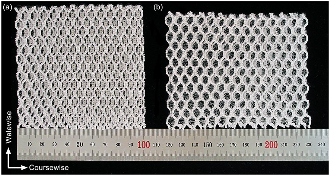
Partial auxeticity of 3D mesh fabric: (a) initial and (b) cyclically compressed.
The 3D mesh fabrics have previously been reported to have auxeticity under uniaxial stretching. The auxeticity was achieved by constructing re-entrant mesh structures by means of special heat setting on conventional fabrics or knitting fabrics with special pattern design and yarn material arrangement.10–17 Wang et al.10–13 compressed a conventional hexagonal 3D mesh fabric in the walewise direction by 50% to a re-entrant V-shaped mesh and simultaneously fixed the geometry by heat setting. Chang et al.14–16 produced a similar V-shaped mesh fabric by adding additional miss-lapping pillar chains into a hexagonal 3D mesh structure. Later, Chang et al. 17 inlaid elastic yarns to a rectangular mesh structure made of stiff yarns, so that the stiff mesh structure was shrank inward after knitting to be re-entrant. Under uniaxial tension, the re-entrant mesh would expand to a rectangular structure and revert to a re-entrant structure, showing the auxeticity. Although the auxeticity of 3D mesh fabrics under stretching in-plane has been realized by using special treatments or knit patterns, the auxetic behavior of conventional 3D mesh fabric under compression has not been noticed till now.
Extensive studies on spacer fabrics have concentrated on elucidating their compression mechanism by examining the deformation of monofilament spacer yarns using experimental, analytical, and numerical methods. The compression mechanism is highly intricate, including post-buckling, shear, rotation as well as contacts of spacer monofilaments with each other and with outer layers in three distinct stages: linear elasticity, plateau, and densification.18,19 In analytical studies, the post-buckling behavior of individual spacer yarn was investigated, based on elastica theory, to understand and predict the compression behavior of spacer fabrics.20,21 A constitutive model was developed to characterize quasi-static compression mechanics and predict dynamic impact energy absorptions of spacer fabrics.22,23 Various finite element (FE) models have been reported to explore the factors affecting the compression properties of spacer fabrics24–29 or to establish geometric structure–property relationships.30–32 However, previous studies have focused only on the deformation of spacer yarns and the interaction between spacer yarns and outer layers. The planar deformation of 3D mesh fabrics under compression was not studied, so the partial auxeticity under compression has not yet been reported.
This work aims to elucidate the partial auxetic mechanism of 3D mesh fabrics under compression, which persists in storage and transportation process and intermittently takes place in cushioning applications, by using experiments and numerical simulation. A precise unit geometric model obtained by X-ray micro-computed tomography (μCT) scanning the fabric presented in Figure 1 is adopted to build a full-size FE model at the yarn level.24–32 The FE model is validated by the compression test results. The partial auxetic mechanism of the 3D mesh fabric is identified from the global to local analysis. A thorough understanding of the partial auxetic behavior of 3D mesh fabrics is achieved from this work. It may inspire fabric and ventilation system producers to jointly find an effective solution to address the dimensional inconsistency in manufacture processes and dimension changes in the subsequent cushioning applications.
Numerical analysis
Geometric model
The 3D mesh fabric was knitted on a double-bar raschel warp knitting machine E12 RD6/3-15 by KARL MAYER, Germany, which is equipped with two needle bars and six yarn guide bars (GB). Two sets of 600D/192F polyester multifilament yarns were used to knit the chain plus inlay in the top mesh outer layer by GB1 and GB2 and the bottom mesh outer layer by GB5 and GB6 separately, as shown in Figure 2(a). A set of polyester monofilament yarns (0.22 mm in diameter) was knitted by GB3 for connecting the two outer layers. The chain notations and yarn materials used are given in Table 1. After stentering and heat setting at 200℃ for 30 s, the fabric has a thickness of 10.3 mm, a stitch density of 7 wale/inch and 18.5 course/inch, and an areal density of 550 g/m2.

Typical 3D mesh fabric: (a) photograph and (b) geometric model of a monofilament unit cell.
Chain notations and yarn materials used for the 3D mesh fabric.

One unit cell of the periodic 3D mesh fabric is dashed in Figure 2(a). A unit cell was previously reconstructed from μCT scanning 31 and is shown in Figure 2(b). It has a length of 14 mm, a width of 7.5 mm, and a thickness of 10.05 mm, and consists of two separate wales of monofilament denoted as mono-1 and mono-2 here. The unit cell can be divided into three layers based on breakpoints defined elsewhere 31 : top mesh layer, spacer monofilaments, and bottom mesh layer. Each mesh layer includes two chains of monofilament loops. Spacer monofilaments are twisted and inclined due to the offset between the two mesh layers.
Finite element model
A full-size FE model for simulating the deformation of a 10 cm × 10 cm fabric under compression is generated by using the unit cell geometric model in Figure 2(b) with LS-PrePost. The FE model is created by repeating the unit cell 7 arrays in the X direction and 13.5 arrays in the Y direction, as shown in Figure 3. To ensure balanced computational efficiency and accuracy, the monofilament in each unit cell is divided into 2000 integrated beam elements with 3 × 3 Gaussian quadrature. The tensile property of the polyester monofilament is provided in Figure 4, and is modeled with *MAT_PIECEWISE_LINEAR_PLASTICITY (024) using a Poisson’s ratio of 0.3 and a density of 1.38 g/cm3. Two 150 mm diameter circular platens are used to compress the fabric, with the top platen applying a displacement and the bottom platen providing support. The two platens are made of rigid shell elements with 1 mm thickness and have a material type of *MAT_RIGID (020) with a Young’s modulus of 200,000 MPa and a Poisson’s ratio of 0.3.

FE model of the 3D mesh fabric.

Tensile property of the monofilament.
Multifilament loops and inlays to constrain monofilaments are physically simulated by using two types of discrete elements. Spring-1 represents multifilament loops to link adjacent monofilament loops, and spring-2 connects mono-1 and mono-2 as multifilament inlays. Figure 5 shows the tensile properties of the multifilament loop and inlay. Their nonlinear tensile load–displacement relationships are modeled with two bilinear elastoplastic springs. To simulate the tight bindings on monofilaments by multifilament loops, rotational degrees of freedom (DOFs) constraints are added along the X- and Y-axes (ROTX and ROTY) at the breakpoints of spacer monofilaments and monofilament loops.
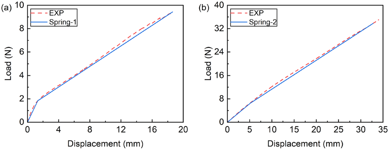
Tensile load–displacement curves and bilinear elastoplastic spring models of multifilaments: (a) multifilament loop and (b) multifilament inlay.
The bottom platen is fixed by constraining both translational and rotational DOFs. A displacement of 8 mm in the negative Z direction is applied to the top platen. It could cover the range of compression in storage and transportation process as well as cushioning applications. All the other translational and rotational DOFs are constrained. The contacts among monofilaments and between monofilaments and platens are detected by using the automatic single surface contact *CONTACT_AUTOMATIC_GENERAL. The static and dynamic friction coefficients are set to 0.28 and 0.27, respectively. 32 The FE model is solved by using the explicit solver LS-DYNA.
Model validation
The fabric of 10 cm × 10 cm size was tested on a universal mechanical test system (Instron 5566) at a compression speed of 10 mm/min. The compression load–displacement curve is compared with the simulation result in Figure 6. A good agreement between experiment and simulation is achieved in the linear elasticity, plateau, and densification stages. The partial auxetic behavior is confirmed experimentally as demonstrated in Figure 1, and the compression load–displacement curve well verifies the simulation. It is reasonable to elucidate the partial auxetic behavior of the 3D mesh fabric under compression by using the simulated fabric deformation.
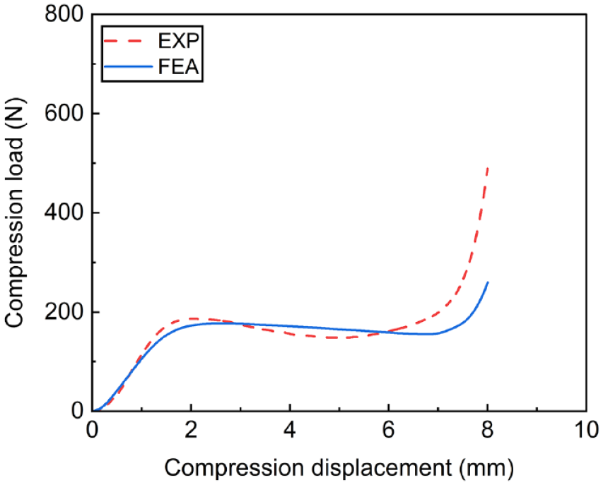
Simulated and experimental compression load–displacement curves.
Fabric deformation
It is hard to experimentally observe the compression deformation of the monofilament architecture of the 3D mesh fabric. FE simulation is able to provide a complete global and local deformation of the 3D mesh fabric under compression. The virtual deformation is analyzed bottom down from fabric global deformation to unit meshes deformation. Later, the detailed partial auxetic deformation is summarized in a representative unit cell.
Fabric global deformation
Fourteen pairs (X1–X14) and eight pairs (Y1–Y8) of reference points are defined on the top mesh layer to detect the variations in length and width, respectively, for quantitatively evaluating the global dimension change of the fabric under compression. The two points of each pair are placed either at the leftmost and rightmost ends or at the uppermost and lowermost ends of the top mesh layer, as illustrated in Figure 7.

Global length and width definition on the top mesh layer: (a) length and (b) width.
The variations of planar length and width of the 3D mesh fabric in compression are exported from the FE simulation and plotted in Figure 8. The length decreases and the width increases as the compression displacement increases. It is shown that the FE simulation successfully reproduces the experimentally observed partial auxeticity that the 3D mesh fabric shortens and widens simultaneously. This unanticipated deformation mode differs from both conventional and perfect auxetic foams which expand and shrink, respectively, in all directions under compression. 33 The curves in Figure 8 are highly nonlinear and diverse, so the partial auxeticity is not only nonuniform in the compression process but also unevenly distributed in the plane of the fabric. On the one hand, the numerical results show that 8% of compression results in a 62.2% of reduction in length. It is considered that the partial auxeticity is especially notable in the initial stage of compression. On the other hand, in the plane of fabric, the wales and courses in the borders have different dimension changes compared with the intermediate wales and courses. For example, in the lengthwise direction, the shrinkage of border wales X1 and X14 is 1.6 and 7.48 times, respectively, that of the intermediate wale X2 at a displacement of 7 mm. In the widthwise direction, the border course Y1 expands more pronounced than intermediate courses (Y2–Y7). This discrepancy between border and intermediate is attributed to their different boundary conditions provided by inlaid yarns and adjacent unit cells. Figure 9 highlights the difference in constraints imposed by multifilament inlays. The loops at two ends of X14 are free due to the absence of inlaid yarns as shown in Figure 9(a) and (b), but the inlays constrain the loops at two ends of X1, as shown in Figure 9(c) and (d). This difference explains why the border wale X14 has a larger variation than intermediate wales X1– X13 in Figure 8(a). It is also noted that the loop at the leftmost of X14 moves away from the fabric, while the loop at the rightmost of X14 moves toward the fabric, leading to the decreasing trend of Y8 in Figure 8(b).

Global planar dimension changes in fabric: (a) length and (b) width.

Boundary conditions in the top mesh layer: (a) upper left, (b) upper right, (c) lower left, and (d) lower right.
In summary, the simulated deformation is consistent with the experimental observation as shown in Figure 1. The simulation further provides a comprehensive view of the global deformation of the 3D mesh fabric under compression. It is found that the dimension change of the 3D mesh fabric is nonuniform both in the compression process and in the plane of the fabric. The nonuniformity in the plane of the fabric results from the varying constraints on monofilament wales provided by multifilament inlays and adjacent unit cells.
Unit meshes deformation
After analyzing the fabric global deformation, here, a wale and a course of meshes are selected, as highlighted in Figure 9, to provide more detailed information on the partial auxeticity of the 3D mesh fabric. The meshes in the wale are named C1–C7 from left to right, and the meshes in the course are named W1–W13 from lower to upper.
The method to measure the length and width of a mesh is illustrated in Figure 10(a). Reference points are placed either at the leftmost and rightmost ends or at the uppermost and lowermost ends of the mesh. Figures 10(b) to (e) show the variation in planar length and width of each selected mesh against compression displacement. Like the global deformation in Figure 8, the curves in Figures 10(b) to (e) are nonlinear and diverse. It is shown that meshes also have nonuniform deformation both in the compression process and in the plane of fabric, indicating that the nonuniform global deformation is the result of diverse deformation of meshes. Border meshes’ lengthwise and widthwise deformation contributes more to the global shortening and widening. In the lengthwise direction, although all meshes (C1–C7) shorten, the border mesh C1 shortens 77.7% of the global deformation of X7 as defined in Figure 7. In the widthwise direction, the expansion mostly concentrates in the border meshes W1 and W13. The other intermediate meshes (W2–W12) supported by adjacent unit cells have nearly unchanged widths. Therefore, an analysis of the unit cell deformation at extremities of fabric is imperative. Since the mesh W13 shortens and widens, which is consistent with the global deformation, the unit cell with top mesh W13 is used for summarizing the partial auxetic deformation.

Dimension definition and dimension changes in meshes: (a) length and width definition in a mesh, (b) change in length of meshes C1–C7, (c) change in width of meshes C1–C7, (d) change in length of meshes W1–W13, and (e) change in width of meshes W1–W13.
The top and bottom mesh deformation of the unit cell with top mesh W13 under compression is presented in Figure 11. The mesh is divided into three regions A–C according to the presence of inlaid yarns. Arrows in two colors are annotated to track the movement trajectories of the monofilament loops. Blue arrows represent the monofilament loops shrinking inward the unit cell, while red arrows represent the monofilament loops expanding outward the unit cell. It is found that in the lengthwise direction, as shown in Figure 11(a) and (b), the shrinkage of the top layer is mainly located at regions A and C, and the shrinkage of the bottom layer appears in all three regions. In the widthwise direction, as shown in Figure 11(c) and (d), the loops of the top mesh layer in region B move outward, whereas the bottom mesh layer expand in regions A and C. Unit cell shortening and widening concentrate in some of regions A–C, and a simplified schematic diagram of mesh deformation is presented in Figure 12. Shortening is located at the regions where loops are constrained with inlaid yarns and ends of the mesh in the lengthwise direction. Widening is located at the regions where loops are without the constraint of inlaid yarns.

Top and bottom mesh deformation of the unit cell with top mesh W13 under compression: in the lengthwise direction, (a) top mesh layer, (b) bottom mesh layer, in the widthwise direction, (c) top mesh layer, and (d) bottom mesh layer.

A schematic diagram of mesh deformation in unit cell: (a) in the lengthwise direction and (b) in the widthwise direction.
Partial auxetic mechanism
The continuous monofilament architecture causes the 3D mesh fabric to deform in the plane perpendicular to the compression force. It is hypothesized that, in the compression process, spacer monofilaments that connect the two mesh layers buckle, thereby driving the in-plane movement of monofilament loops. The fabric shrinks lengthwise and expands widthwise, showing partial auxeticity. The unit cell with top mesh W13, as denoted in Figure 9, is also selected here to analyze the deformation of its monofilament architecture for confirming this hypothesis on the partial auxetic mechanism.
Figure 13(a) presents the deformation of the entire unit cell. Three selected parts in three regions are highlighted and denoted as A, B, and C. Each of the three parts has eight spacer monofilaments and eight monofilament loops. In Figures 13(b) to (d), three parts A–C in mono-1 are divided into four spacer monofilaments and four monofilament loops by using the breakpoints A1–A9, B1–B9, and C1–C9 following the method reported elsewhere. 31 These segments are quantitatively analyzed with curvature and torsion. 34 It is confirmed that the movement of loops is dragged by post-buckled spacer monofilaments. For example, the monofilament loop A3–A4 retains a constant curvature, but varies in torsion, suggesting that it twists or rotates around its own axis without altering its overall shape. In contrast, the spacer monofilament A4–A5 varies in both curvature and torsion, indicating a great deviation from its initial curved shape and twisted direction. These findings suggest that monofilament loops move primarily due to the deformation of spacer monofilament, not inherent loop deformation.
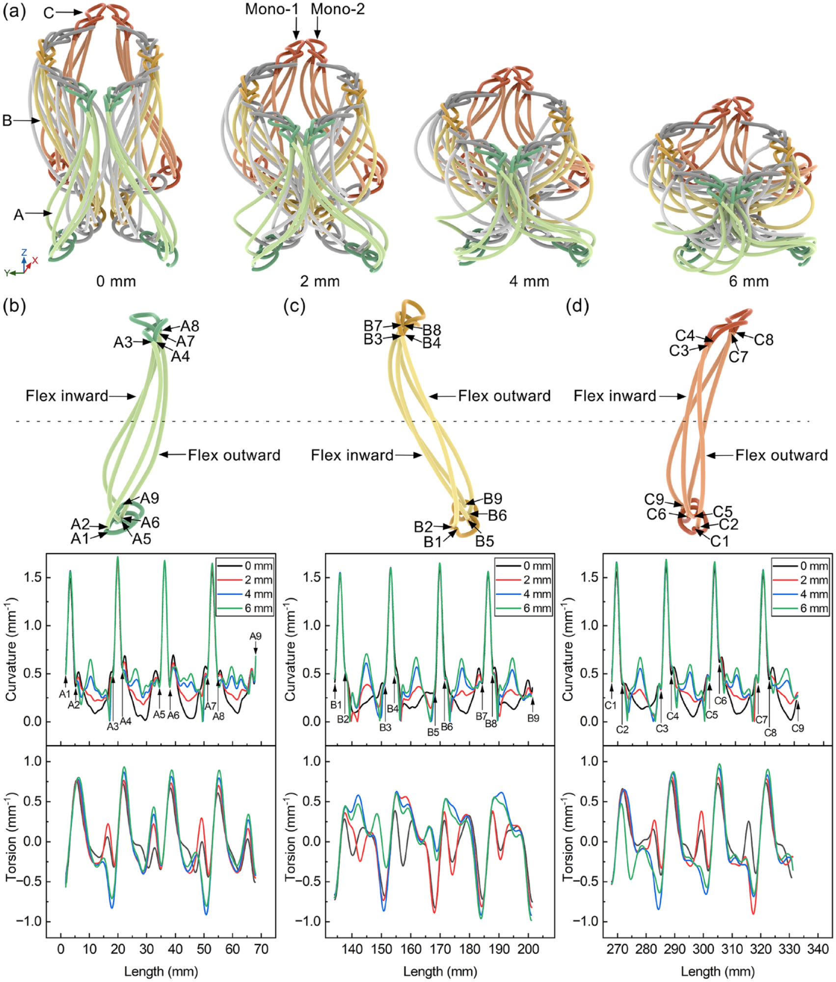
Geometry, curvature, and torsion at different compression displacements: (a) geometry, curvature and torsion in (b) part A, (c) part B, and (d) part C.
The specific moving direction of monofilament loops, which contributes to the planar partial auxeticity observed in the 3D mesh fabric, is the result of the respective buckling direction of spacer monofilaments. As shown in Figures 13(b) to (d), each spacer monofilament can be divided into an upper half and a lower half by their initially flexing direction. The segments, which flex inward the unit cell, account for the lengthwise shrinkage of the unit cell. As seen in Figure 13(a), the loops in lengthwise shrinking regions are connected with the spacer monofilaments flexing inward, and the loops in widthwise expanding regions are connected with the spacer monofilaments flexing outward. Under compression, initially flexing inward segments would buckle inward, and initially flexing outward segments would buckle outward, thereby driving specific moving directions of monofilament loops. Meanwhile, the widthwise expansion would also drive the lengthwise shrinkage in meshes, since separate monofilament wales are linked by inlaid yarns forming an integrated structure. As the compression continues, the spacer monofilaments intercontact and become densified, which provides less space for spacer monofilaments buckling further, so the movement of loops is restricted, thereby weakening the partial auxeticity. This causes nonuniform partial auxeticity in the compression process. The intermediate unit cells are more easily densified due to the surrounding of adjacent unit cells, which would provide less space for flexed segments to buckle, so their partial auxeticity is weaker than those of the border unit cells. This results in nonuniform partial auxeticity in the plane of fabric.
A schematic diagram of the partially auxetic mechanism of the 3D mesh fabric under compression is illustrated in Figure 14. The 3D mesh fabric exhibits partial auxeticity mainly due to the compression-induced shortening and widening of the border unit cells. The spacer monofilaments act as compression load carriers, of which the flexing inward segments buckle inward, leading to the lengthwise shrinkage of unit cells, and the flexing outward segments buckle outward, leading to the widthwise expansion of unit cells. Meanwhile, the widthwise expansion drives the lengthwise shrinkage due to the chain inlays. The deformation in meshes gives rise to the observed partial auxetic behavior of fabric.

A schematic diagram of partial auxeticity: (a) in a unit cell and (b) in a fabric.
Conclusions
A full-size FE model of a 3D mesh fabric under compression was established and validated. The partial auxetic mechanism of the fabric was identified based on the analysis of global fabric deformation, unit meshes deformation, and unit cell geometric structure change from the validated FE model. Following conclusions can be drawn.
(1) 3D mesh fabrics exhibit partial auxeticity, which shorten and widen under compression due to their 3D integrated structures. Post-buckled spacer monofilaments buckle under compression, driving the in-plane movement of monofilament loops.
(2) The flexing inward segments of spacer monofilaments buckle inward the unit cell, and the flexing outward segments of spacer monofilaments buckle outward the unit cell, which drive the inward movement of loops in the lengthwise direction and outward movement of loops in the widthwise direction, causing partial auxetic behavior under compression.
(3) The partial auxeticity of 3D mesh fabrics weakens in the compression process due to the gradual intercontact and densification of spacer monofilaments. Flexed segments of spacer monofilaments have less space to buckle further, thereby weakening the partial auxetic behavior.
(4) The partial auxeticity of 3D mesh fabrics is nonuniformly distributed among meshes due to their different boundary conditions. Different constraints on monofilament wales provided by adjacent unit cells and multifilament inlays provide varying space for flexed segments to buckle, which makes the partial auxetic behavior nonuniform in the plane of fabric.
This study reveals the planar deformation mode of 3D mesh fabrics under compression. It is foreseeable that 3D mesh fabrics for cushioning applications will shorten and widen after using a period of time. It also suggests that when unrolling and laser cutting 3D mesh fabrics, it is crucial to take into account the dimension changes with partial auxeticity under compression. In this work, we only elucidate the fact that compression brings the in-plane dimension change, but the time-dependent dimension recovery in the decompression process is not studied. In future work, it is important to quantify the relationship between the recovery of the partial auxeticity-induced deformation changing with time, and explore potential methods for compensating this time-dependent deformation to ensure dimensional precision.
Footnotes
Declaration of conflicting interests
The author(s) declared no potential conflicts of interest with respect to the research, authorship, and/or publication of this article.
Funding
The author(s) disclosed receipt of the following financial support for the research, authorship, and/or publication of this article: This work was supported by the National Natural Science Foundation of China (grant number 11702062).