
Abstract
Three-dimensional (3D) mesh fabric is a key component in ventilated car seats for its excellent cushioning and ventilating performance. It is produced by stretching an as-knitted spacer fabric with closed surfaces via stentering and fixing the mesh form via heat-setting. This paper analyzes the effect of stentering and heat-setting processes on the structures and compression properties of a typical and commercial 3D mesh fabric by using X-ray micro-computed tomography (μCT) and finite element (FE) models. The monofilament architectures of the fabric after knitting, stentering, and heat-setting are reconstructed from μCT scanning, and the structural evolution is quantitatively investigated in terms of global dimension change, curvature, and torsion. The results from μCT reconstructions demonstrate that stentering shortens, widens, and thins the fabric due to yarn transfer to shorten monofilament loops and lengthen spacer monofilaments, which are then dispersed, bent, and twisted to increase the curvatures and torsions. The FE simulations indicate that the global and local monofilament architecture deformation shifts the fabric compression mode from constrained post-buckling to concurrent tilting and post-buckling of spacer monofilaments, expanding the plateau stage and decreasing plateau stress. Heat-setting shrinks monofilament and therefore deteriorates its mechanical performance. The fabric is further thinned during the heat-setting process, which also further bends and twists spacer monofilaments to slightly decrease the plateau stress. The structures and cushioning performance of 3D mesh fabrics can be engineered by employing a proper stentering ratio followed by a heat-setting process.
Keywords
Introduction
Ventilation systems have been established by incorporating fans or blowers into the clothing of cooling vests or cushions of ventilated automotive seats and mattresses to realize personalized temperature control while saving energy.1–6 The diffusion layer that helps to swiftly flow and evenly distribute air, thus delivering a cooling effect, should possess not only high air permeability but also adequate compression resistance. A 3D mesh fabric structure, as shown in Figure 1(a), is an excellent candidate with integrated channels for the diffusion layer to provide effective circulating air flow and desirable cushioning support.7,8 It has two pliable polyester multifilament mesh outer layers connected by countless stiff polyester spacer monofilaments via embedding monofilament loops into multifilament loops, as illustrated in Figure 1(b). The mesh outer layers are formed by joining separate wales of loops with inlaid yarns. 3D mesh fabrics are a special type of spacer fabric that is distinctive from metal fibrous laminated sandwich panels9,10 in two respects: (a) it is a continuous one-piece structure rather than a discretely stiffened laminated structure, and (b) it is stiff through the thickness but flexible out-of-plane. Both multifilament and monofilament yarns are continuous and periodically intermeshed in the fabric. This gives rise to a highly nonlinear and inhomogeneous structure. The geometry and arrangement of spacer monofilaments determine the air permeability and compression resistance of 3D mesh fabrics. 3D mesh fabric structure: (a) fabric; (b) geometric model.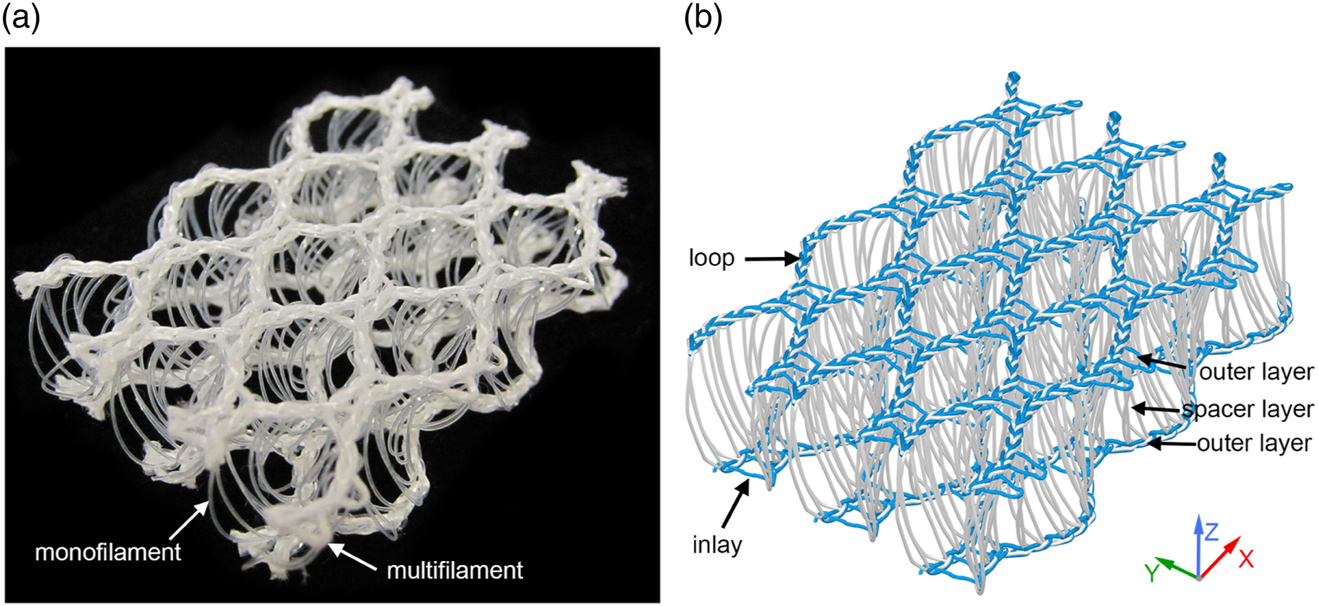
Extensive studies have focused on revealing the influence of spacer fabric structures on compression properties using experiments and simulation. The compression stress–strain curves of various spacer fabrics with different spacer monofilament arrangements and outer layers were measured to show linear, plateau, and densification stages, which is the typical feature of cushioning materials.11–13 The three distinct stages are attributed to post-buckling, torsion, shear, rotation, and the contacts of the spacer monofilaments, as well as the contacts between the spacer monofilaments and outer layers. 13 It was also shown that a thicker spacer fabric knitted with finer spacer monofilaments less oriented to the thickness direction and bound by larger mesh outer layers has lower compression resistance.11–13 By making different simplifications, finite element (FE) methods have been used to numerically simulate the compression behavior of spacer fabrics with closed surfaces. Various FE models were built by using a single or an array of identical and discrete spacer monofilament of assumed geometry, simplifying the outer layers as isotropic plates, and assigning linear elastic materials.14–17 Intermeshed monofilament loops embedded in the outer layers were considered by the FE models in Refs.18,19, but the spacer monofilament geometries were still not realistic, and the material models were linear elasticity. X-ray micro-computed tomography (μCT) was used to scan spacer fabrics with meshed7,8,20–23 or closed outer layers24–27 to obtain authentic geometries of spacer monofilaments. The true geometries and material nonlinearity of spacer monofilaments were employed to establish FE models for those fabrics with closed surfaces by treating the outer layers as isotropic and elastic plates.25–27 The verified FE models indicate that linear elasticity and plateau stages are mainly a result of post-buckling and rotation of spacer monofilaments, while torsional deformation and contacts among spacer monofilaments dominate in the densification stage.25–27
The outer layers of finished spacer fabrics with closed surfaces are nearly the same as those of the as-knitted fabrics.11–13 By contrast, the outer layers of 3D mesh fabrics, which are initially closed, should be stretched coursewise to form different sizes of meshes in the stentering and heat-setting process.7,23 Meanwhile, the thickness, air permeability, and compressibility of 3D mesh fabrics were changed. A previous experimental investigation showed that stretching the fabric in the coursewise direction decreased the fabric thickness and compressibility but enhanced the air permeability through the thickness. 28 Structural analyses of 3D mesh fabrics using μCT indicated that the monofilament architecture is different from that of spacer fabrics with closed surfaces.7,23 Unfortunately, research on how stentering and heat-setting quantitatively affect the monofilament architecture and compressibility of 3D mesh fabrics is still lacking. This work sets out to unravel the effect of stentering and heat-setting on the structure and compression behavior of 3D mesh fabric using X-ray micro-computed tomography and microscopic modeling.29–31 A thorough understanding of the complex process-structure-property (P-S-P) relationships of 3D mesh fabrics is achieved from this work.
Fabric structural analysis
Fabric details
The fabric presented in Figure 1(a) was knitted on a SGE2298 double-needle bar Raschel warp knitting machine of gauge E12 equipped with six guide bars (Changzhou Saijia Machinery Co., Ltd., Changzhou, Jiangsu, China). The course density is set as 6.5 courses per centimetre and the knock-over comb bar distance is set as 11.8 mm. Each outer layer was knitted with two sets of 600D/192F polyester multifilament yarns (Hengli Group Co., Ltd., Suzhou, Jiangsu, China), while one set of 600D/1F (0.25 mm in diameter) polyester monofilament yarns (Kunshan Litai Fiber Co., Ltd., Suzhou, Jiangsu, China) was alternately intermeshed into the two separate outer layers, thereby forming a one-piece sandwich fabric. The as-knitted fabric has a periodic pattern, and one of the unit cells is dashed in Figure 2(a). A single unit cell is cut from the as-knitted fabric, as shown in Figure 2(d). It shows that the meshes on the surfaces of the fabric after knitting are not evident. To open the meshes on the surfaces, the as-knitted fabric is stretched coursewise (Y-axis) to 2.45 times its initial width through a stentering process, as shown in Figure 2(b). The photo was taken when the fabric was stretching, and one of the unit cells is enlarged in Figure 2(e). To retain the mesh form, the stretched fabric was heat set at 200°C for 60 s under tension, and the finished fabric is shown in Figure 2(c). The dashed unit cell was cut from the finished fabric and is shown in Figure 2(f). Photographs of the fabric after (a) knitting, (b) stentering, and (c) heat-setting; a unit of the fabric after (d) knitting, (e) stentering, and (f) heat-setting.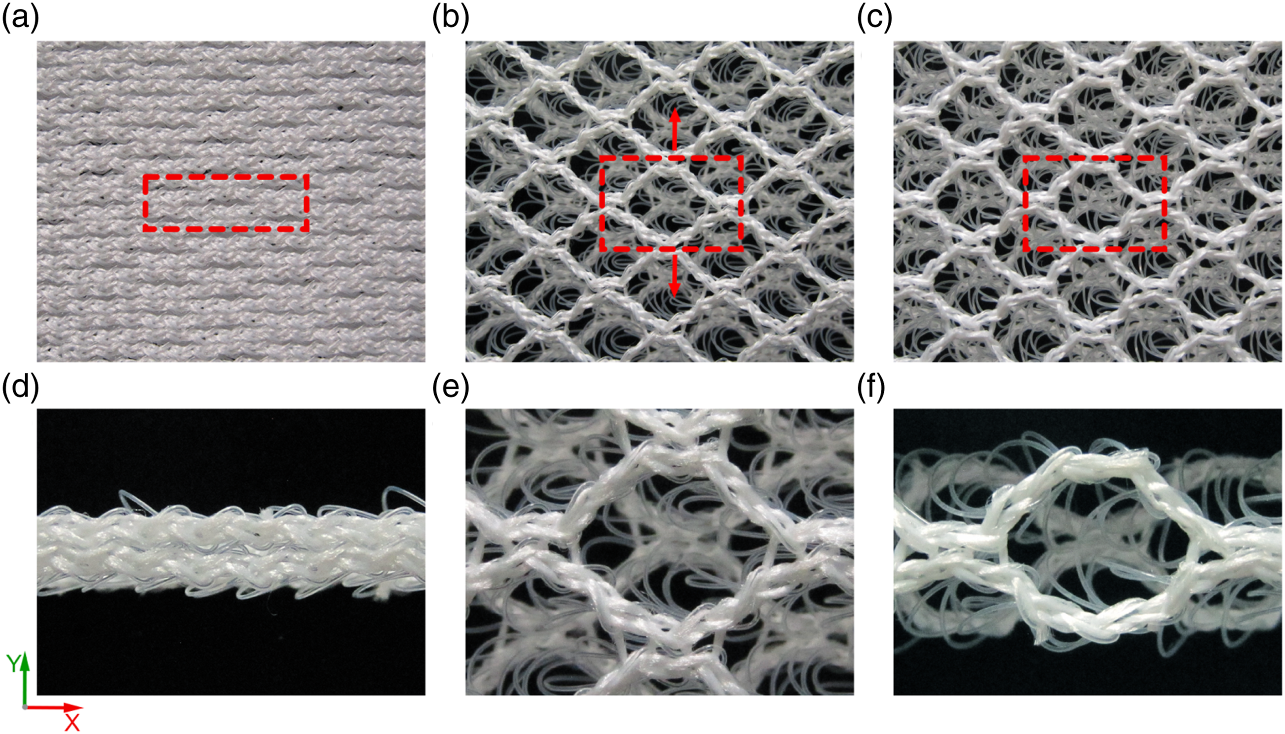
μCT scanning
X-ray micro-computed tomography scanning was carried out on the fabric in the three states to obtain their accurate monofilament architectures. All fabric samples were embedded in paraffin to ensure no dimensional change in μCT scanning. Since the fabric after stentering cannot retain its geometry, paraffin embedding was conducted under tension, as illustrated in Figure 3(a). A bespoke stentering frame with two parallel needle bars was used to stretch the fabric coursewise and constrain it walewise from shrinking. A certain amount of melted paraffin wax was poured into the stretched fabric. When paraffin wax was solidified, a part of the stretched fabric containing two units was cut, as shown in Figure 3(b). All the fabric samples were scanned on a μCT system (YXLON CT Modular) for an exposure duration of 0.70 s at 100.0 kV and 200.0 μA. The element size was 18.9335 μm. A slice of the outer layer is shown in Figure 3(c), in which white areas represent sections of monofilament loops and grey areas represent multifilament loops. Figure 3(d) presents a slice of the spacer monofilaments, in which the white ellipses are the monofilament cross sections. The two slices demonstrate that the geometric details of the fabric are captured by μCT scanning. Stretched fabric sample preparation for μCT scanning: (a) paraffin embedding process; (b) stretched fabric embedded in paraffin; (c) a slice of outer layer; (d) a slice of spacer monofilaments.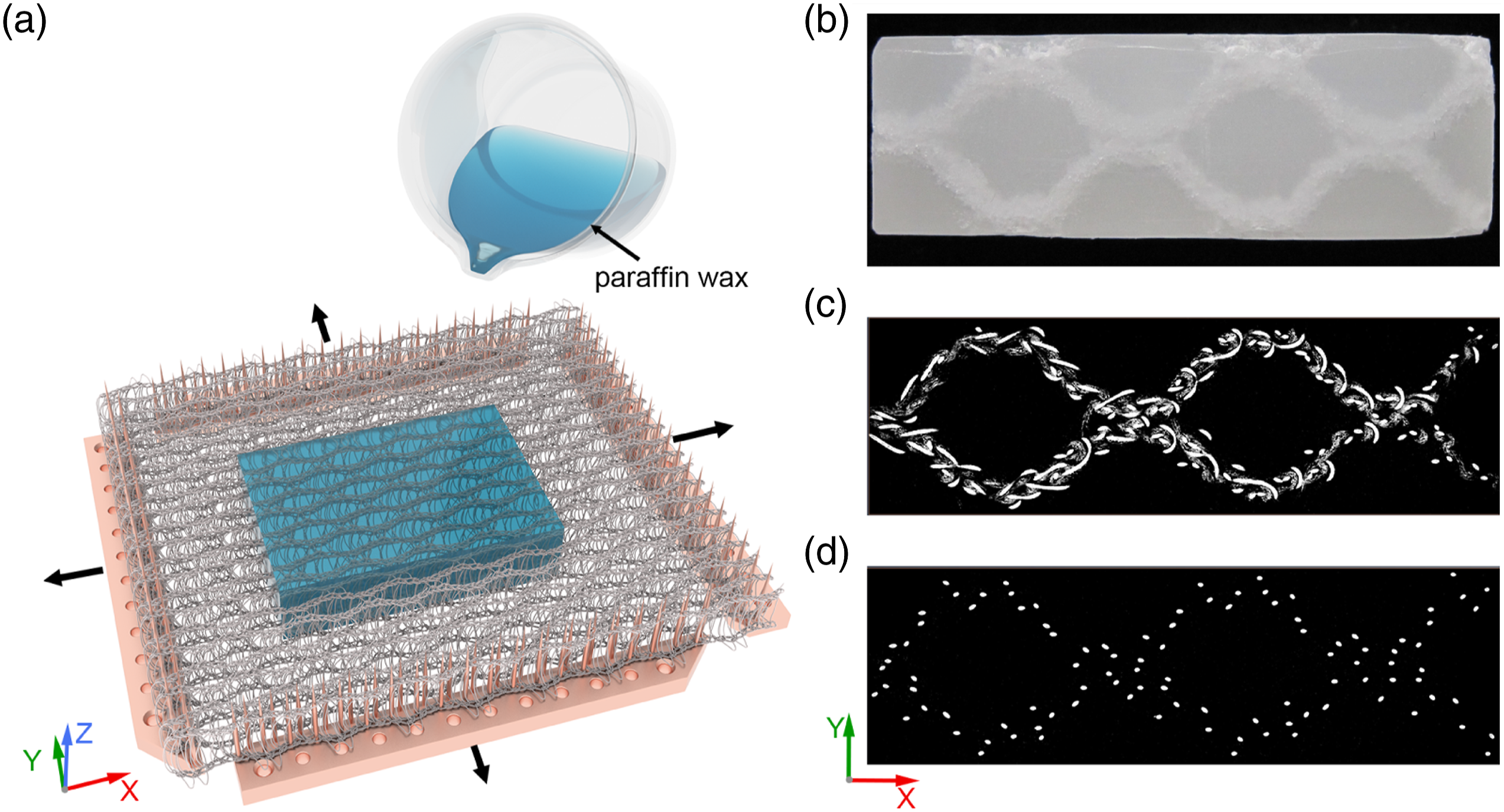
Avizo (Konrad-Zuse-Zentrum für Informationstechnik Berlin (ZIB), Germany) is a powerful 3D data visualization, analysis, and modeling system.
32
All the slices obtained from scanning the three fabric samples were loaded into Avizo 9.0.1 by stacking the images in sequence for volume rendering, and their 3D reconstructions are shown in Figure 4(a) to (c). The intermeshed monofilament loops are well reconstructed, but individual filaments in the multifilament loops are not precisely reproduced due to the resolution limit of the μCT system. XFiber Extension built in Avizo 9.0.1 offers automatic and interactive tracing tools for segmenting the centerline of fibers or filaments. It was used to automatically trace the centerlines of the monofilaments, and the results are shown in Figure 4(d) to (f). The multifilament yarns and artifacts are removed from the 3D reconstructions. μCT reconstruction of the fabric after (a) knitting; (b) stentering; (c) heat-setting and filament tracing of the fabric after (d) knitting; (e) stentering; (f) heat-setting.
Structural analysis
Monofilament architecture unit cells of the fabric samples after knitting, stentering, and heat-setting are established as shown in Figure 5 by assigning a diameter to the centerlines of the monofilaments. The diameter for the as-knitted and stretched fabric samples is 0.25 mm, while that for the finished fabric sample is 0.26 mm due to shrinkage. The monofilament architectures clearly demonstrate the structural evolution from as-knitted fabric to finished fabric. Each unit cell includes two intermeshed monofilaments. Here, the left and right monofilaments are denoted by mono-1 and mono-2, as annotated in Figure 5(a). There are 10 top loops and 10 bottom loops connected by 20 spacer monofilaments for each monofilament. Monofilament architecture unit cells of the fabric after knitting (a) and (d), stentering (b) and (e), and heat-setting (c) and (f).
The as-knitted fabric has two similar intermeshed monofilaments, as shown in Figure 5(a) and (d). Their monofilament loops are left- and right-leaning alternately. The four chains formed by the four wales of loops are relatively straight, so the outer layers are closed initially. Their spacer monofilaments are buckled but oriented in the thickness direction. After stentering, the four chains of the stretched fabric are changed from straight to sinusoidal, and the spacer monofilaments are inclined as shown in Figure 5(b) and (e). Stentering strained the initially loose inlaid yarns, and an offset of threading inlaid yarns resulted in displaced meshes on the two outer layers. The rotation directions of the top and bottom monofilament loops are opposite, which twists the spacer monofilaments. It is considered that the two intermeshed monofilaments are broadly symmetrical. After heat-setting under tension, both multifilament and monofilament yarns shrank, thereby further changing the fabric’s monofilament architecture. Figure 5(c) and (f) show that the monofilament loops are intermeshed more tightly and the spacer monofilaments are also inclined more. The diameters of the original monofilament and those cut from the three fabric samples were measured by using a scanning electron microscope, as given in Figure 6. It shows that knitting and stentering have little effect on the monofilament diameter, but an increase of 9.5 μm was observed after heat-setting. The dimensions of the fabric in the three states are measured on their μCT reconstructed monofilament architecture unit cells, as listed in Table 1. The unit cell after stentering and heat-setting is shortened walewise (X-axis), widened coursewise (Y-axis), and thinned (Z-axis). Monofilament diameter change: (a) original; (b) after knitting; (c) after stentering; (d) after heat-setting. Dimensions of the fabric after knitting, stentering and heat-setting.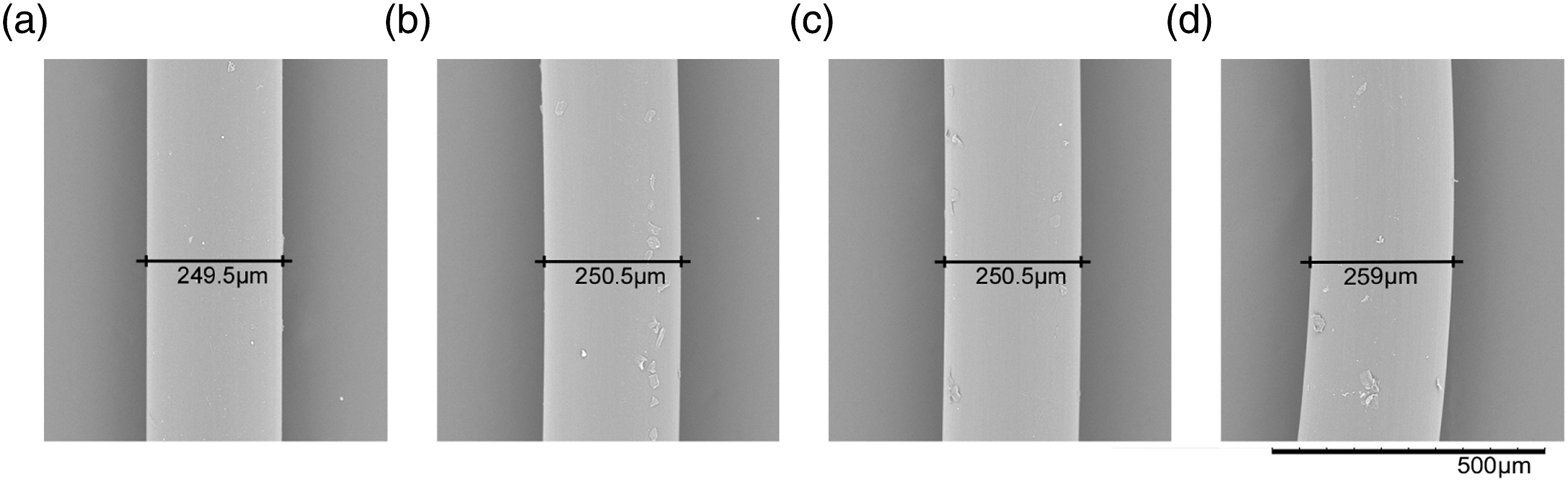

Curvature and torsion are the amounts by which a curve deviates from being a straight line and a plane curve, respectively. For a space curve r(t) = [x(t),y(t),z(t)] parametrized by a parameter t, the curvature κ(t) and torsion τ(t) can be calculated by
and
, respectively. 33 The curvature and torsion of the two monofilaments were calculated along the length to evaluate the local geometric changes resulting from stentering and heat-setting.
It is shown in Figure 7 that the curvature curves of the monofilaments in the three fabric samples have similar nonlinear and periodic characteristics. There are 20 pronounced peaks for each monofilament, which demonstrate how much the loops are bent. They have different peak values, which are 1.233–1.326 mm−1 for the as-knitted fabric, 1.235–1.347 mm−1 for the stretched fabric, and 1.331–1.467 mm−1 for the finished fabric. Stentering slightly increases the loop curvature, while heat-setting dramatically shrinks the loops, thereby substantially increasing the loop curvature. The curvatures of spacer monofilaments in the as-knitted fabric fluctuate in a relatively narrow range of 0.067–0.300 mm−1. After stentering, the curvatures of spacer monofilaments slightly increase to a range of 0.09–0.309 mm−1. After heat-setting, the spacer monofilaments have curvatures distributed over a wide range of 0.039–0.600 mm−1. Hence, spacer monofilaments are bent more after heat-setting than after stentering. Curvature–length curves of the two monofilaments: (a) mono-1; (b) mono-2.
The torsion curves of the monofilaments in the three fabric samples are plotted in Figure 8. Their periodically oscillated torsions include two types of conjoint peaks: a positive peak followed by a negative peak in the solid line box denoted by PN, and vice versa, in the dashed box denoted by NP. Two PN peaks and two NP peaks repeatedly appear in all the curves. This is because the adopted chain notation 1010/0101//, which determines the monofilament architecture, changes the yarn’s overlapping direction every course in the production. For instance, as can be seen in Figure 5(a), mono-2 is overlapped from left to right to form the first course of the top loop and bottom loop, and it is overlapped from right to left to form the two loops in the second course. Those torsion curves have shown that the overlapping directions of the top and bottom loops determine the way to twist the spacer monofilament. The as-knitted fabric has relatively uniform torsion distribution in the repeats of the two monofilaments, approximately ranging from −0.6 to 0.6 mm−1. As the fabric is stretched, both the top and bottom loops are rotated and sinusoidally distributed. The torsion distribution is also shifted to a sinusoidal pattern in a wider range of −0.768–0.762 mm−1. The sinusoidal torsion distributions of mono-1 and mono-2 have a phase difference of 180°, so they are broadly symmetrical. After heat-setting, the sinusoidal torsion distribution is retained, but the torsion range of the finished fabric is further widened, varying from −0.788 to 0.809 mm−1. It is noteworthy that stentering and heat-setting reduce the uniformity of torsion. In some repetitions, the peak torsions are significantly decreased. Monofilament shrinkage can bring about uncertain torsional deformation to monofilament architecture. Torsion–length curves of the two monofilaments: (a) mono-1; (b) mono-2.
A repeat including two PN and two NP torsion peaks is selected from mono-1 and presented in Figure 9 along with their curvature curves and geometries in order to analyze the detailed local deformation of the monofilament architecture. Nine break points (P1–P9) dividing mono-1 into four loops and four spacer monofilaments are defined according to the distinct inflection points from the curvarure curves. The four peaks P2–P3, P4–P5, P6–P7, and P8–P9 correspond to the curvatures of the four monofilament loops. It is shown that the finished fabric has higher curvature peaks than the as-knitted fabric and stretched fabric. This is because the loops are shortened after stentering and heat-setting. Taking the loop P2–P3 as an example, its loop length decreases from 4.493 mm to 4.006 mm after stentering due to yarn transfer and further decreases to 3.709 mm after heat-setting because of yarn shrinking. Spacer monofilaments bend asymmetrically compared to monofilament loops. For example, spacer monofilament P3–P4 of the three fabrics shows an initial increase in curvature before changing into an inverted parabola-like pattern, which is enclosed in the dashed box, and then a decrease in curvature as shown in Figure 9(a). The as-knitted fabric has the flattest and lowest inverted parabola among the three fabrics. After stentering, the length between P3 and P4 increases from 15.394 mm to 15.528 mm, the parabola is slightly altered with increasing curvature, and it is more bent as shown in Figure 9(c). After heat-setting, the spacer monofilament P3–P4 was shrunk to 14.510 mm, and it is highly bent with the highest parabola. The top and bottom loops are rotating oppositely in the stentering process, as shown in Figure 9(b) and (c). The rotation of loops twists the spacer monofilaments. There are four modes of twisting spacer monofilaments, as illustrated in the torsion curves. The torsions at their two ends are positive–positive, negative–positive, negative–negative, and positive–negative in sequence. All the torsion curves of the spacer monofilaments are fluctuating and crossing zero several times, indicating a complicated twisting behavior. Basically, stentering and heat-setting result in more twisted spacer monofilaments with higher curvatures, as shown in Figure 9(b) to (d). By contrast, the torsion of the two loops P2–P3 and P4–P5 changes linearly from positive to negative, and the other two are just opposite. Hence, monofilament loops have spatial shapes rather than planar ones, and their twisting directions shift at the point of zero torsion. Curvature and torsion of mono-1 and the geometry: (a) curvature and torsion; and the geometries after (b) knitting; (c) stentering; (d) heat-setting.
In summary, stentering and heat-setting processes change the monofilament architecture of the 3D mesh fabric globally and locally. Stentering shortens, widens, and thins the fabric globally by transferring yarn to shorten monofilament loops and lengthen spacer monofilaments, which bend and twist the spacer monofilaments to increase the curvatures and torsions. Heat-setting shrinks both monofilament loops and spacer monofilaments, which further thins the fabric and bends and twists spacer monofilaments. The complex change in monofilament architecture definitely affects the compression behavior of the 3D mesh fabric.
Modeling of compression behavior
The compression behavior of the 3D mesh fabric in the three states is studied experimentally and numerically.
Tensile and compression tests
The monofilaments unraveled from the three fabric samples were tested on a universe mechanical tester (YG028) manufactured by Ningbo Dahe Instrument Co., Ltd., Zhejiang, China, according to the British standard BS EN 13,895:2003 Textiles – Monofilaments – Determination of tensile properties at the standard environment of 20°C and 65% humidity. The original monofilament for knitting the 3D mesh fabric was also tested for comparison. A gauge of 250 mm and a pretension of 0.05 ± 0.005 cN/dtex were adopted, and the test speed was 250 mm/min. 10 specimens were tested for each monofilament, and the strain–stress data were recorded.
The as-knitted fabric and the finished fabric were tested on the same universal mechanical tester set up with two compression square platens of 100 mm in side length according to the Standard Test Methods for Rubber Properties in Compression ASTM D 575. The size of all the specimens was 100 mm × 100 mm. The compression tests were conducted at a speed of 10 mm/min up to a deformation of 80% of the initial thickness of each fabric in an environment of 20°C and 65% relative humidity.
Finite element models
The three geometric models shown in Figure 5 are used to generate the three finite element (FE) models for the fabrics after knitting, stentering, and heat-setting by using LS-PrePost. Figure 10 presents the FE model for the finished fabric as an example, and the settings of the other two FE models for the as-knitted fabric and stretched fabric are the same. Each monofilament is meshed with 2000 integrated beam elements in 3 × 3 Gauss quadrature. Discrete spring elements are used to physically simulate the constraints on the monofilaments provided by the multifilament loops and inlays, as illustrated in Figure 1. Spring I represents multifilament loops to connect adjacent monofilament loops with four springs, and spring II represents multifilament inlays to connect mono-1 and mono-2 together. The spring stiffness has a nonlinear force–displacement relationship. For simplicity, the two types of spring systems under tension and compression were modeled with the same force–displacement relationship, y = 0.1x2. All rotational degrees of freedom of the node at the break point between spacer monofilament and monofilament loop are constrained because this point is constrained by the inlaid yarns. FE model of the 3D mesh fabric after heat-setting.
Two compression platens are meshed with shell elements of edge length 0.3 mm, and assigned *MAT_RIGID (020) with steel’s properties (ρ = 7.85 g/cm3, ν = 0.3, E = 200,000 MPa). All translational and rotational degrees of freedom of the bottom platen are constrained. The top platen is subjected to a compression displacement in the negative Z direction that is equal to 80% of the initial thickness, while the other translational and rotational degrees of freedom are constrained.
The interaction among spacer monofilaments is detected by single surface contact (*CONTACT_AUTOMATIC_GENERAL). The contacts between the spacer monofilaments and the platens are simulated with automatic contact (*CONTACT_AUTOMATIC_NODE_TO_SURFACE). All the nodes in the monofilaments are set as slave nodes, while the platens are set as the master surface. The coefficients of dynamic and static friction are 0.27 and 0.28, respectively.
An isotropic linear elasto-plastic material model [*MAT_PIECEWISE LINEAR_PLASTICITY (024)] from the LS-DYNA material library is selected to simulate the constitutive behavior of monofilaments in the three FE models. The deviatoric stresses are determined that satisfy the yield function
where
where 
where σ t , ε t , and E are true stress, true strain and elastic modulus, respectively.
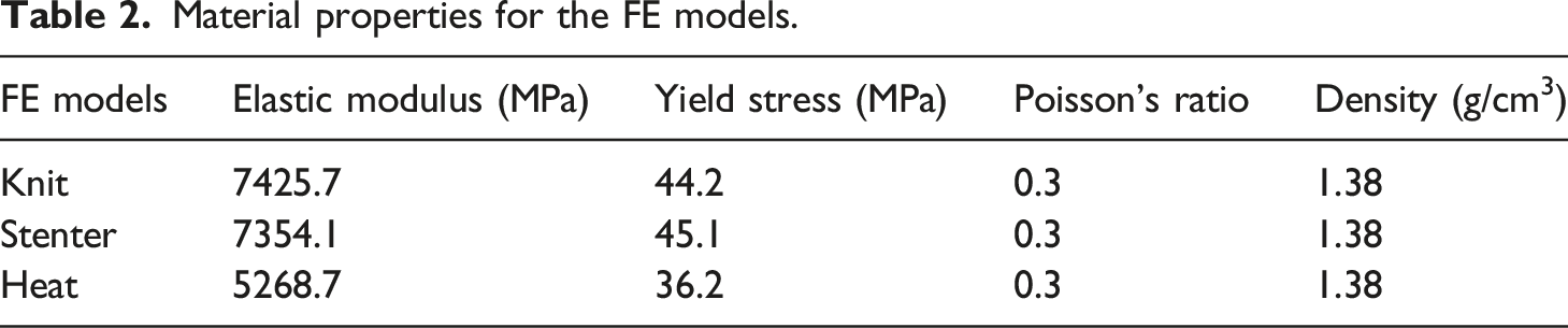
The true stress–strain curves of the monofilaments are shown in Figure 11(a). It shows that the tensile property is deteriorated after knitting, but the stress–strain relationship remains unchanged after stentering. Heat-setting further deteriorates the tensile performance. The elastic moduli and yield stresses of monofilaments unraveled from the as-knitted, stretched, and finished fabrics are calculated from the true stress–strain curves and listed in Table 2 as the material property inputs for the FE simulations. In addition, the density and Poisson’s ratio are 1.38 g/cm3 and 0.3, respectively, for all the FE models. The effective stress–strain curves of the monofilaments are calculated by equation (5) and plotted in Figure 11(b), which are also input to LS-DYNA. Tensile properties of the monofilaments: (a) true stress–strain curves; (b) effective stress–strain curves. Material properties for the FE models.
Simulation of compression properties
The three FE models are solved using the explicit solver LS-DYNA. Figure 12(a) compares the simulated and experimental compression load–displacement curves. The fabric after stentering without heat-setting cannot keep the stretched state, so only the FE result is presented. Those compression load–displacement curves are also converted to stress–strain curves and plotted in Figure 12(b) by considering the increase in area and decrease in thickness after stentering and heat-setting. A good agreement between the FE predictions and experimental results is achieved for the as-knitted and finished fabrics. It is shown that all the curves have three distinct stages, including elasticity, plateau, and densification.11,12 After stentering and heat-setting, the compression force of a unit decreases in all three stages. By taking the enlarged area and decreased thickness into account, the compression stress–strain curves of the stretched and finished fabrics are similar, but they move down significantly compared with the as-knitted fabric. Hence, the synergistic stentering and heat-setting process is an effective way to engineer the compression resistance of 3D mesh fabrics to meet the requirements of specific applications. Simulated and experimental results: (a) compression load–displacement curves; (b) compression stress–strain curves.
Stentering lengthens, bends, and twists the spacer monofilaments, thereby reducing their capacities to resist compression loading in all three stages. Heat-setting not only further bends and twists the spacer monofilaments but also deteriorates the monofilament’s mechanical performance. As a result, the compression resistance of the finished fabric decreases, although the monofilament is shortened and thickened. In addition, both the simulated and experimental compression load–displacement curves of the as-knitted fabric have rapidly increasing slopes in the latter part of the plateau stage. By contrast, the stretched and finished fabrics possess flat and stable plateau stages in the simulated curves. A slight decrease in compression force is observed in the plateau stage of the experimental curve of the finished fabric. This difference is attributed to their different monofilament architectures. The spacer monofilaments in the as-knitted fabric are compactly arranged, and their interactions provide extra constraints on themselves. This phenomenon can be confirmed from the Von Mises stress plots of the fabrics compressed at different displacements, as shown in Figure 13. When the displacement ranges from 1 to 4 mm, the interactions among the two wales of monofilaments in the as-knitted fabric are not evident. As the displacement reaches 6 mm, there are plenty of contacts among the spacer monofilaments. Those contacts restrict tilting of post-buckled spacer monofilaments, so their two end sections formed line-to-surface contacts with the two rigid platens as illustrated in Figure 13(d) and (e). The intermediate sections that effectively resist compression loading are shortened accordingly, thereby increasing the compression resistance. Stentering disperses the spacer monofilaments over a larger area. The two wales of spacer monofilaments are highly unlikely to contact each other, so they undergo post-buckling and tilting freely in the compression process without obvious line-to-surface contacts with the platens. Those highly bent and twisted spacer monofilaments cannot effectively bear the compression loading, so the compression resistance is kept relatively constant in a wide range up to a displacement of 8 mm. Heat-setting further thins the fabric and increases its spacer monofilaments’ curvature and torsion, but the monofilament architecture is similar. Figure 13(a) to (e) demonstrates that the deformation modes of the stretched and finished fabrics in the elasticity and plateau stages are also similar. This explains why their compression load–displacement curves or stress–strain curves are similar. It is noteworthy that the plateau stage of the finished fabric is narrowed a little due to the decrease in thickness. At a displacement of 8.5 mm, the compression reaches the densification stage. As illustrated in Figure 13(f), post-buckling of spacer monofilaments still predominates the deformation of the as-knitted fabric to resist compression, but the stretched and finished fabrics are crushed and densified. Von Mises stress plots of the fabrics compressed at different displacements: (a) 1 mm; (b) 2 mm; (c) 4 mm; (d) 6 mm; (e) 8 mm; (f) 8.5 mm.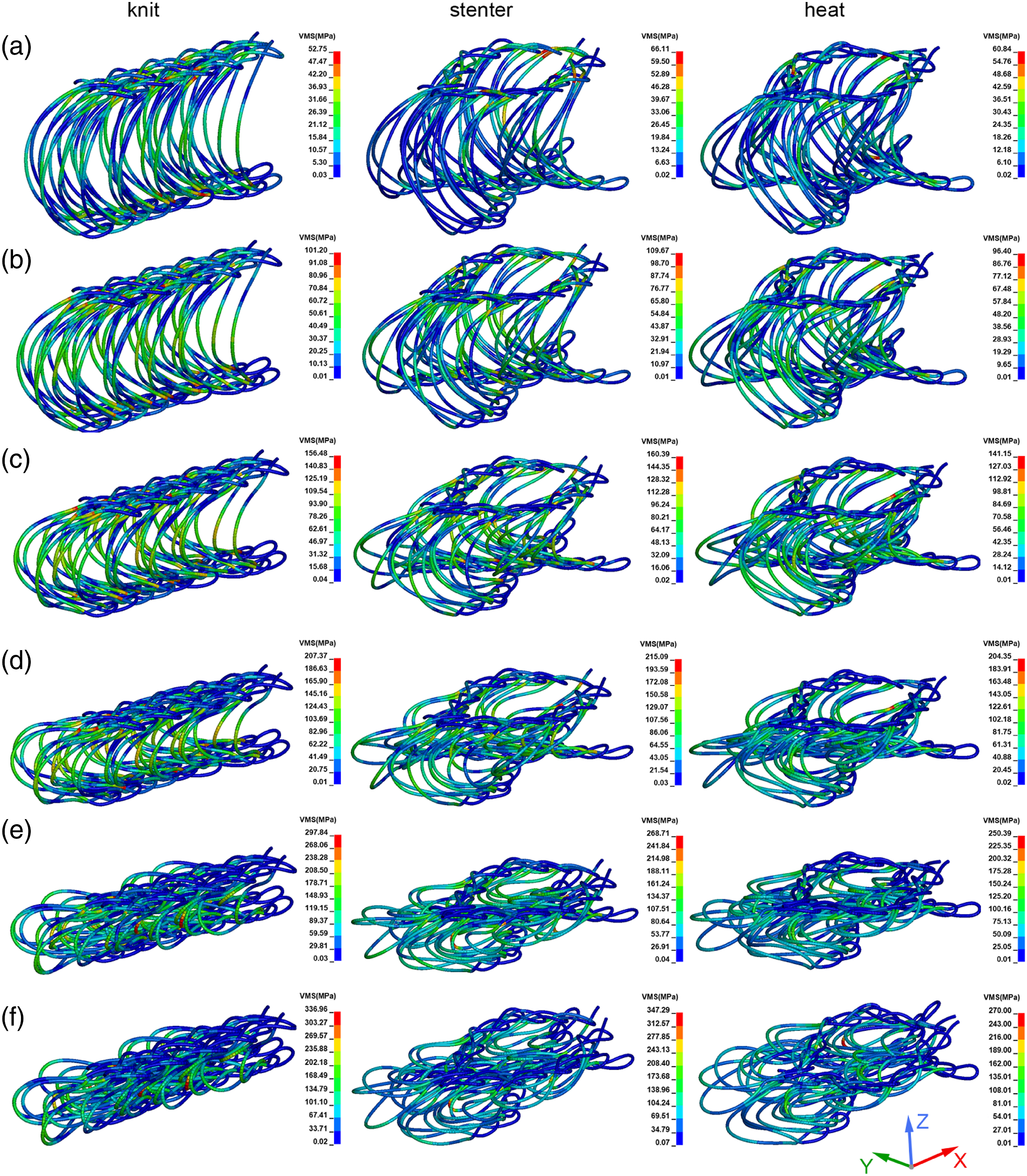
Stentering opens the fabric meshes through dispersing, bending, and twisting the spacer monofilaments, which changes the compression mode from constrained post-buckling to simultaneous tilting and post-buckling, widening the plateau stage to behave like a typical cushioning material. Fixing the stretched geometry by heat-setting further shortens, bends, and twists the spacer monofilaments, which has little effect on the deformation mode but slightly decreases the plateau stress.
Conclusions
The structures and compression properties of a typical 3D mesh fabric in its as-knitted, stretched, and finished forms were investigated experimentally and numerically to get an in-depth understanding of the complex process-structure-property relationship. The effect of stentering and heat-setting on the monofilament architectures reconstructed from μCT scanning was quantitatively analyzed in terms of dimension, curvature, and torsion. The compression behavior of the fabrics was FE simulated and experimentally verified. From the structural analysis and compression simulation, the following conclusions can be drawn. (1) Stentering the as-knitted fabric in the coursewise direction shortens, widens, and thins the fabric, during which monofilament loops are shortened and spacer monofilaments are lengthened due to yarn transfer. This process opens the meshes, disperses the spacer monofilaments and also bends and twists the spacer monofilaments, thereby increasing the curvatures and torsions. (2) Heat-setting the stretched fabric shrinks monofilament loops and spacer monofilaments and therefore further thins the fabric and bends and twists spacer monofilaments. The mechanical properties of monofilament deteriorate after heat-setting due to shrinkage. (3) The compact arrangement of spacer monofilaments in the as-knitted fabric constrains themselves in post-buckling under compression, increasing compression resistance throughout the elasticity, plateau, and densification stages. Sparse, bent, and twisted spacer monofilaments after stentering bring about a wider plateau stage with a much lower and constant plateau stress, resulting from simultaneous post-buckling and tilting of spacer monofilaments. Heat-setting slightly decreases the compression resistance of the finished fabric, and its compression mode is similar to that of the stretched fabric.
The findings suggest that stentering is a simple and effective way to manipulate the cushioning behavior of 3D mesh fabrics, and FE modeling based on the accurate monofilament architecture is powerful to predict the compression resistance for a specific stentering ratio. This work successfully elucidates the structural evolution of 3D mesh fabrics during the manufacturing process and devises a numerical strategy to optimize the cushioning performance.
Footnotes
Declaration of conflicting interests
The author(s) declared no potential conflicts of interest with respect to the research, authorship, and/or publication of this article.
Funding
The author(s) disclosed receipt of the following financial support for the research, authorship, and/or publication of this article: This work was supported by the National Natural Science Foundation of China (grant number 11702062).