
Abstract
This study establishes a fiber inclination model suitable for a new three-dimensional angle interlocking woven UHMWPEF/epoxy composite, and evaluates its anti-penetration performance. Specifically, the microstructural characteristics of the composite material were analyzed by CT scan images, the mesostructure model of the material was established with the help of the software TexGen, and the calculation method of the fiber volume fraction of the material was designed. The meta-software ANSYS/LS-DYNA simulated and analyzed the failure mode and stress after ballistic penetration, before verifying it with the ballistic penetration test of the composite material as the target. The results show that the fiber volume fraction of the material is calculated to be 49.5% according to the derivation formula, which is consistent with that measured in the laboratory (50%±1%). By simplifying the numerical simulation model of composite ballistic penetration with the “fiber inclination model,” the residual velocity of the projectile calculated is in good agreement with the experimental value with an error of <7%. In the target penetration test, the damage patterns of the target surface and the ejection surface are similar to the numerical simulation results. In the fiber inclination model, the failure shape of the projectile penetrating the horizontal one-way plate is almost circular, while the failure shape in the inclined one-way plate is irregular with a more severe damage along the inclined direction. In both unidirectional plates the damage area of the incoming surface is smaller than that of the ejected surface. Therefore, it is valid to use the fiber inclination model established to study the penetration performance of composite materials.
Keywords
Introduction
The three-dimensional woven composite material is formed by intertwined fiber bundles to form a spatial network structure in the woven fabric as a reinforcement and cured by a matrix. It not only has the characteristics of traditional fiber-reinforced composite materials, such as light weight, high specific strength and damage resistance, but also fundamentally overcomes the weakness of laminated composites that are easy to delaminate under impact loads. Therefore, it is widely used in aerospace, shipbuilding, and automotive industries, and especially has good application prospects in the field of protection engineering.
At present, the anti-penetration performance of composite materials is mainly studied by two methods: experimental test and numerical simulation. The test method analyzes the damage form of the composite material after being penetrated by the projectile body in the most intuitive and accurate way, but has the disadvantages of high cost and inability to accurately study the penetration damage process. In contrast, the numerical simulation method has the advantages of high efficiency, low cost and high flexibility. It is able to conduct a more comprehensive analysis of the anti-penetration property of 3D woven composite materials, which is feasible for in-depth study of the stress change and failure mechanism during the ballistic penetration of composite materials. The fiber inclination model is widely used due to the advantages of simple establishment process, high simulation accuracy and high computational efficiency compared to others.1 –4
Previously, by using LS-DYNA to simulate the penetration process of three-dimensional orthogonal woven composites, in which the target plate adopts the orthotropic constitutive model with damage and the Hashin failure criterion, Yu et al. 5 found that the residual velocity of the projectile and the failure form of the target plate were in good agreement with the penetration test results. Yang et al. 6 simplified the complex geometric structure of 3D woven composites and predicted their mechanical properties by the proposed “fiber inclination model.” By comparing with the experimental results, they verified the rationality of the “fiber inclination model” for predicting the mechanical properties of composite materials. Sun and Qiao 7 improved the “fiber inclination model” by simplifying the four-step braided composite material into four unidirectional boards with the same properties, and verified the rationality of the fiber inclination model by comparing the predicted and the measured strengths. Gu et al. 8 simplified the structure of the 3D woven composite material by the “fiber inclination model,” simulated the process of the projectile penetrating the target plate, and analyzed the anti-penetration performance of the material. By establishing the fiber inclination model of the composite material and combining it with the classical composite laminate theory, Cui 9 obtained the mechanical performance parameters of the unidirectional plate, analyzed the penetration failure mechanism of the three-dimensional angle-interlock composite material, and verified the inclination model. Yang et al. 10 considered the inclined arrangement of the weft yarns in the thickness direction after curing the composite material, and established a three-dimensional woven composite material inclination model based on the assumption that the cross-section of the weft yarn is a lenticular lens and the cross-section of the warp yarn is a rectangular cross-section. They deduced the mathematical relationship between the fiber volume fraction and the meso-structural parameters such as warp density, weft density and yarn inclination in composite materials. Turner et al. 11 used solid elements and membrane elements to establish a meso-structure model of 3D woven composites at the yarn-resin scale, respectively, and used LS-DYNA to simulate the ballistic penetration of the composite target plate, to analyze the failure process and stress changes of fibers and resins in the process of penetration at the mesoscopic level. Karahan and Ahmed 12 provides an overview of the relevant literature on simulation and modeling of composites used for protection against ballistics and blasts and presents three case studies related to personal safety and protection using composites subjected to ballistic and blast loads.
In the study of mechanical properties of 3D woven composites, the fiber volume fraction is one of the key factors affecting their mechanical properties, whose accuracy of prediction is of great significance. In the fiber inclination model, the mechanical parameters of each unidirectional plate are different for 3D woven composites with different structures, which directly affect the model accuracy. Therefore, it is important to determine the fiber volume fraction and the mechanical properties parameters of the unidirectional plate first when studying the mechanical properties of new woven composites based on the “fiber inclination model.” This study takes a new type three-dimensional angle-interlock woven composite material as the research object, which was prepared from ultra-high molecular weight polyethylene fiber (UHMWPEF) and epoxy resin by vacuum-assisted resin infusion molding.13,14 Its mesostructural features were analyzed based on CT scans, and the fiber volume fraction was calculated by the established the calculation method. By combining with the classical composite material unidirectional plate theory, the mechanical performance parameters of the unidirectional plate were determined, and the fiber inclination model was established. Finally, the numerical simulation analysis of projectile penetration was carried out, and the accuracy of the model was verified by the penetration test of the composite target plate.
Microstructure analysis of 3D woven composites
Mesostructure analysis based on CT images
In studying the structure of UHMWPEF/epoxy woven composite material, its weaving parameters are shown in Table 1.
Weaving parameters of three-dimensional angle interlocking woven composites.

The CT scan images of the composite material are shown in Figure 1. Four sections are selected along the directions of the binding warp yarn and the weft yarn in the fiber reinforcement. Specifically, the warp section 1-1, 2-2, 3-3 and 4-4 were cut at the midline position of the binding warp yarn, between the adjacent binding warp yarns, of the weft yarn, and between the adjacent weft yarns, respectively. The key meso-geometric parameters of each component of the composite material were marked with a ruler representing actual distance of 1 mm, which was calculated according to fact that the width of one pixel on the CT image represented 20.85 μm. The meso-geometric parameters in multiple cross-sectional images were measured by software ImageJ, and the actual measurement results are shown in Table 2.

CT scan images of 3D angle-interlock woven UHMWPEF/epoxy composite: (a) meridian section 1-1, (b) meridian section 2-2, (c) weft section 3-3, and (d) weft section 4-4.
The meso-geometric parameters of 3D angle-interlock woven composite.

The three-dimensional corner interlocking woven UHMWPEF/epoxy composite contains two yarn systems, curved binding warp yarns and straight weft yarns. According to the characteristics of the internal space structure, the composite material is divided into a surface area and an internal area along the thickness direction. The surface area is greatly disturbed by the outside, with unstable structures and obvious deviation of the weft yarn, while the internal area is less disturbed by the outside, and the yarns are more compact. In the surface area, since the difference between the layers of two adjacent rows of weft yarns is 2, the row with fewer layers of weft yarns will leave “holes.” Since there is no warp yarn binding between the outermost two layers of weft yarns in a row with many layers of weft yarns, there would also be “holes.” These “holes” in the composite are filled by the matrix, resulting in a smaller fiber volume content in the surface region than in the interior region.
Due to the mutual extrusion between the binding warp and the weft, the cross-sectional shape of the yarn changes from an ideal circle to an oval shape. Meanwhile, since the binding warp yarn is more compressed than the weft yarn, it contains an elliptical cross-section with a larger ratio of the major and minor axes.
3D woven composite mesoscopic solid model
According to the characteristics of the geometric cross-sectional shape of the yarn in the composite material, the following assumptions are made to establish a mesoscopic solid model:
The extrusion degree of the yarn in the composite material is uniform, and the cross-sectional shape of the yarn are consistent along the yarn path. The cross-sectional shape of the binding warp and weft yarns are both oval, the binding warp height Hj and the weft height Hw are the short axes of the ellipse, and the binding warp width Wj and the weft width Ww are the long axes of the ellipse, as shown in Figure 2.
The weft yarns are aligned layer by layer on the short axis direction of the elliptical cross section, and the weft yarn path remains straight.
During the curing process of the material, the shape of the yarn does not deform, and the matrix material is evenly distributed in the gap between the yarns.

Schematic diagram of cross-sectional shape of: (a) weft yarn and (b) the binding warp.
Based on the mesoscopic geometric parameter measurements of the composite material, a mesoscopic solid model of the composite material is established by TexGen,15 –17 as shown in Figure 3.
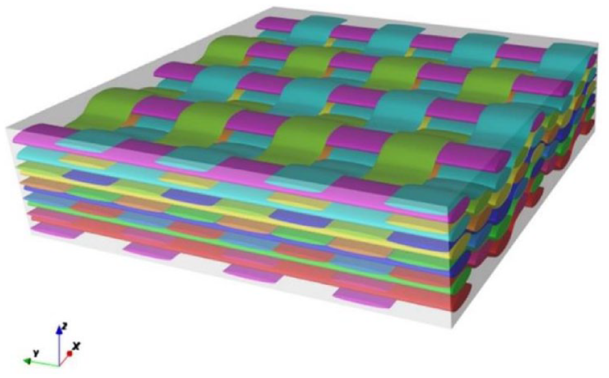
Mesoscopic solid model of 3D woven composites.
It can be seen from Figures 4 and 5 that the mesostructure of the three-dimensional angle interlocking woven composite material has obvious periodic characteristics. A representative volume unit (full-scale unit cell) of the same thickness as the composite material was observed and extracted from the in-plane direction, as shown in Figure 6.

Comparison between meridional section in the mesoscopic solid model of 3D woven composite and the CT image.

Comparison between weft section in the mesoscopic solid model of 3D woven composite and the CT image.

Full-size unit cell section of 3D woven composites: (a) top view, (b) weft direction, and (c) warp direction.
The lengths

The thickness of the full-scale unit cell, that is, the thickness h of the composite material is as follows.
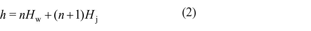
In the formula, n is the number of layers of weft yarns.
There is also a repetitive structure in the inner region of the full-size unit cell, and it is possible to continue to extract smaller representative volume units (inner unit cells) from the inner region of the full-size unit cell, as shown in Figure 7. At present, scholars usually assume that the cross-sectional size of 3D woven composites is large enough to ignore the influence of the surface area of the material, and regard the composite as the assembly of countless continuous inner unit cells.
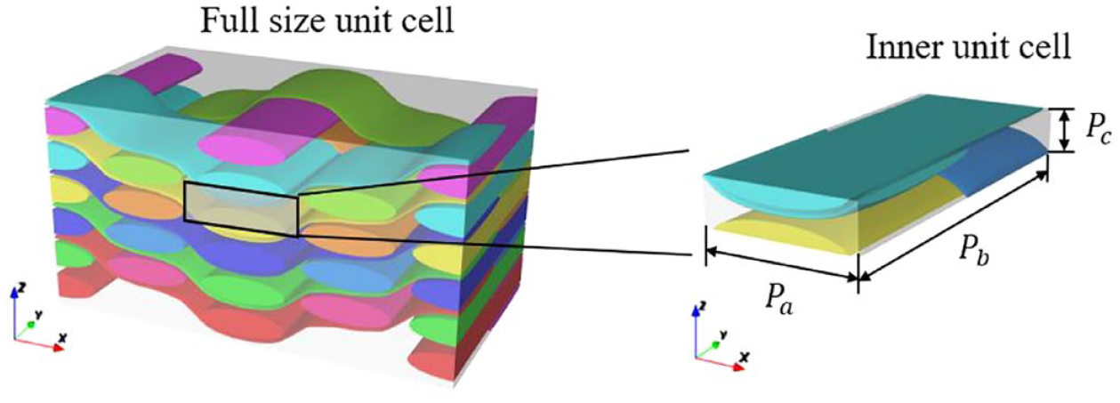
The inner unit cell of 3D woven composite.
The lengths

If the three-dimensional woven composite material is considered to be composed of countless inner unit cells, the thickness

Fiber volume fraction of 3D woven composites
Fiber volume fraction refers to the ratio of fiber to material volume in composites, and is one of the key factors affecting the macroscopic mechanical properties of 3D woven composites. Its accuracy in the composite model depends to a large extent on the simulation degree of the meso-geometric model. 18 The path of the binding warp yarns in the meso-geometric model can best reflect the mesoscopic structural features of the 3D woven composites, while the curved binding warp yarns are entangled between the weft layers. Its position is difficult to determine, so the description of the binding warp yarn trajectory is the key to the meso-geometric model.
The meso-geometric model of three-dimensional angle-interlock woven composite established on the basis of the meso-solid model is shown in Figure 8. Wherein, the warp direction is the x-axis, the weft direction is the y-axis, the short-axis direction of the elliptical cross-section of the yarn is the z-axis, and the binding warp trajectory is represented by a dash dot line in the figure. The weft spacing in the inner area of the composite material is half of the outermost weft spacing, and the outermost weft spacing can be obtained from the weft density, so the weft spacing


Mesoscopic geometric model of the 3D angle-interlock woven composite.
In the meso-geometric model of the three-dimensional angle interlocking woven composite material, it is assumed that the path of the binding warp is connected by a continuous number of one-fourth elliptical arc segments, as shown in the figure AB, BC, CD and DE. The major axis radius

The length

The cross-sectional shapes of the binding warp and weft are both elliptical, then the cross-sectional areas

Yarn fineness is defined as the weight in grams per 9 km long fiber bundle at a given moisture regain, in denier (abbreviated as “d”). Then the cross-sectional area A (unit is mm2) of the fiber bundle in the yarn can be expressed by the yarn fineness T and the fiber filament density, as follows.

The fiber filling factor refers to the volume fraction of fiber filaments in the yarn. The fiber filling coefficients

where
According to the periodicity of the mesostructure of the three-dimensional angle-interlock woven composite, the full-size unit cell as its representative volume unit can reflect the overall mesostructure of the composite material. Therefore, the fiber volume fraction of the composite can be obtained by calculating the fiber volume fraction of the full-size unit cell.
The fiber volume content
The fiber volume content

The total volume V of the full-size unit cell is as follows.

The fiber volume fraction in the full-size unit cell is the fiber volume fraction

According to the measured mean value of the meso-geometric parameters of the CT image, and using equations (11)–(14), the fiber volume fraction of the three-dimensional angle-interlock woven UHMWPEF/epoxy composite was calculated to be 49.5%, which is consistent with the fiber volume fraction of the composite material measured in the laboratory (50% ± 1%).
Fiber inclination model
Establishment of fiber inclination model
Since the mesoscopic structure of 3D angle-interlock woven composites is too complicated to establish a solid geometric model, and limited by the compute capability, the “fiber inclination model” is adopted to simplify the mesoscopic structure of the geometric model of 3D woven composites. The smallest representative volume unit (inner unit cell) in the composite material is considered to be composed of two upper and lower layers of fiber bundles and two spatially diagonal fiber bundles of a cuboid, as shown in Figure 9. Considering each layer of fiber bundles and resin in the inner unit cell as a composite unidirectional board, each inner unit cell is divided into two layers of unidirectional boards up and down and two layers of unidirectional boards along the diagonal direction, as shown in Figure 10. The width, length and thickness of the inner unit cells together determine the angle and position of fiber laying in the four unidirectional boards. The inner unit cell was repeatedly extended along the x, y, and z directions to obtain the overall model of the composite material. The composite material can be regarded as a combination of four unidirectional boards with different fiber-laying directions.

Internal unit cell structure of 3D woven composites.

The inner unit cell in the fiber inclination model of 3D woven composite.
In order to facilitate the analysis of the mechanical properties of the one-way plate and the establishment of the model, this paper uses the theoretical knowledge of the “fiber inclination model” to make the following assumptions about the fiber inclination model: (1) In the unidirectional board, the fiber arrangement direction is straight, and the fiber laying direction is parallel to the side length of the unidirectional board, without considering the buckling and torsion of the fibers. (2) The fibers are arranged evenly in the unidirectional board, and the space outside the fibers in the unidirectional board is filled with resin. (3) The four unidirectional plates in a single cell have the same properties and thickness, and the fiber volume fraction of each unidirectional plate is consistent with the composite material, without considering the intersection and overlap between the four unidirectional plates.
In the fiber inclination model, the tilt angle of the unidirectional plate, which is the angle of fiber laying, has a great influence on the ballistic penetration of the composite material. From Figure 9, the angle θ between the inclined one-way plate and the horizontal plane can be calculated from the unit cell thickness

The thickness of the four unidirectional boards is one-fourth of the overall thickness of the composite material, while the width b of the horizontal unidirectional board and the inclined unidirectional board is the same as the width
Where
According to the structural characteristics of one-way plate in the three-dimensional angle-interlock woven composite, the inclined one-way plate model is shown in Figure 11.

Geometric diagram of the inclined one-way plate model.
Determination of material parameters in fiber inclination model
The unidirectional plate in the fiber inclination model is to homogenize the mesoscopic structure, regardless of the distribution and interaction of fibers and resins in the composite material plate, so the unidirectional plate can be regarded as a transversely isotropic material. The mechanical performance parameters of the one-way plate are calculated using the classical one-way plate theory, as shown in formula (17).

In the formula, E1, E2, and E3 represent the tensile modulus of the unidirectional board in the longitudinal, transverse and thickness directions, respectively. ν12, ν13, ν23 and G12, G13, G23 represent the Poisson’s ratio and shear modulus in the 12, 13, and 23 directions, respectively.
Numerical simulation of penetration resistance of composite materials based on fiber inclination model
Model building
Both the projectile body and target plate are selected as 8-node hexahedral reduced integral solid elements (3D solid 164). The element is suitable for situations where collisions and large deformations occur, but the use of this element may result in hourglass phenomena. To avoid the occurrence of the hourglass, it is necessary to control the hourglass properly. When the hourglass energy does not exceed 5% of the total energy, the hourglass mode has little impact on the calculation results. When the hourglass energy exceeds 10% of the total internal energy, it indicates that the analysis results are invalid.
The projectile is made of isotropic rigid balls. During the penetration test, the projectile hardly deforms, so it can be regarded as a rigid material. *MAT_RIGID is selected as the material model of the projectile. The material parameters of the projectile are shown in Table 3.
Projectile material parameters.

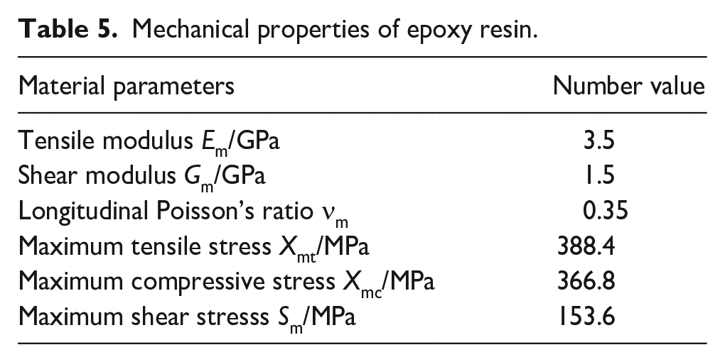
The mechanical property parameters of UHMWPEF fibers in the three-dimensional angle-interlock woven composites are shown in Table 4, 19 and the mechanical property parameters of epoxy resin are shown in Table 5. 19
UHMWPEF mechanical properties parameters.

Mechanical properties of epoxy resin.
According to the mechanical properties parameters of UHMWPE fiber and epoxy resin, the mechanical properties parameters of the unidirectional board in the fiber inclination model are calculated by the classical composite laminate theory, as shown in Table 6. 19
One-way plate mechanical performance parameters.

The shear strength, transverse tensile strength and transverse compressive strength of the one-way plate are taken as the strength of the matrix, and the longitudinal tensile strength of the unidirectional plate is the product of the modulus of the composite material and the failure strain. 5 The shear stress-strain of the material is considered to be linear, and the nonlinear shear stress parameter is taken to be 0.
During the process of projectile penetration, three-dimensional woven composite materials may exhibit matrix cracking, lateral compression failure, and fiber fracture failure. And the target plate material adopts MAT_COMPOSITE_DAMAGE constitutive model containing the Chang-Chang failure criterion. Due to the complex failure modes of materials during projectile penetration, in addition to the three types of damage mentioned above, other forms of damage may also occur due to the sustained development of certain types of damage. The failure of composite materials can be corrected by adding the additional strain failure criterion (MAT_ADD_EROSION) in the k-file.
Numerical simulation results and analysis
Rreferring to the measured velocity of the projectile in the ballistic penetration test of 3D woven composite materials, the processes of projectile penetrating the composite target plate at the incident velocities of 272, 276.6, 332.9 and 356.3 m/s were simulated and analyzed. Taking the projectile incident velocity of 272 m/s as an example, the representative horizontal one-way plate and inclined one-way plate in the fiber inclination model of the composite material were selected to analyze the failure mode and stress distribution of the material at different time points during the penetration process. The penetration process of the first horizontal one-way slab is shown in Figure 12.
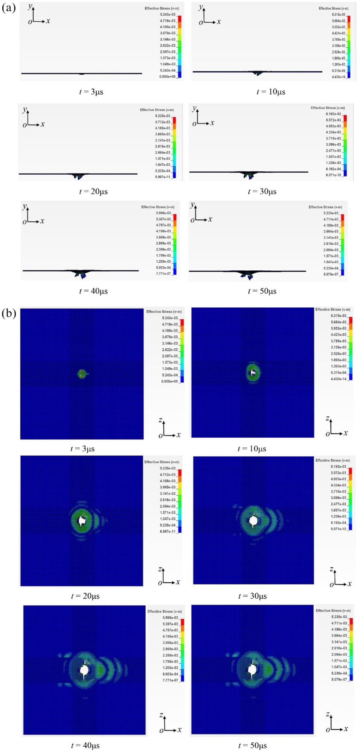
The failure state of the projectile penetrating the first horizontal one-way plate at different time points: (a) side view and (b) top view.
By observing the failure process of the projectile penetrating the first horizontal one-way plate, we found that at 3 μs in the penetration process, there is a depression on the incoming surface, the stress propagates in the circular area centered on the impact point of the projectile, a bulge appears on the ejection surface, and the ejection surface begins to bend and deform. When the penetration process reaches 10 μs, due to the low strength of the matrix, the one-way plate breaks, fragments on the ejection surface begin to fall off, and the stress concentrates on the contact position between the projectile and the one-way plate. As the penetration process continues from 10 μs to 40 μs, the contact area between the projectile and the one-way plate becomes larger, the stress in the one-way plate propagates further along the fiber axial direction, and the concave surface on the projectile surface becomes more obvious. Along with the projectile penetrating the one-way plate, the fragments on the ejection surface keep falling off. After 42 μs, the projectile speed basically remains unchanged, and the first horizontal one-way plate has been completely penetrated. It is found that the damage areas of the incoming surface and the ejecting surface of the one-way plate are significantly smaller than that of the ejecting surface. On the impact and ejection surfaces of the one-way plate after penetration, it is found that the damage area of the impact surface is obviously smaller than that of the ejection surface.
Figure 13 shows the stress distribution and failure form of the second inclined one-way slab at different timepoints during the penetration process.
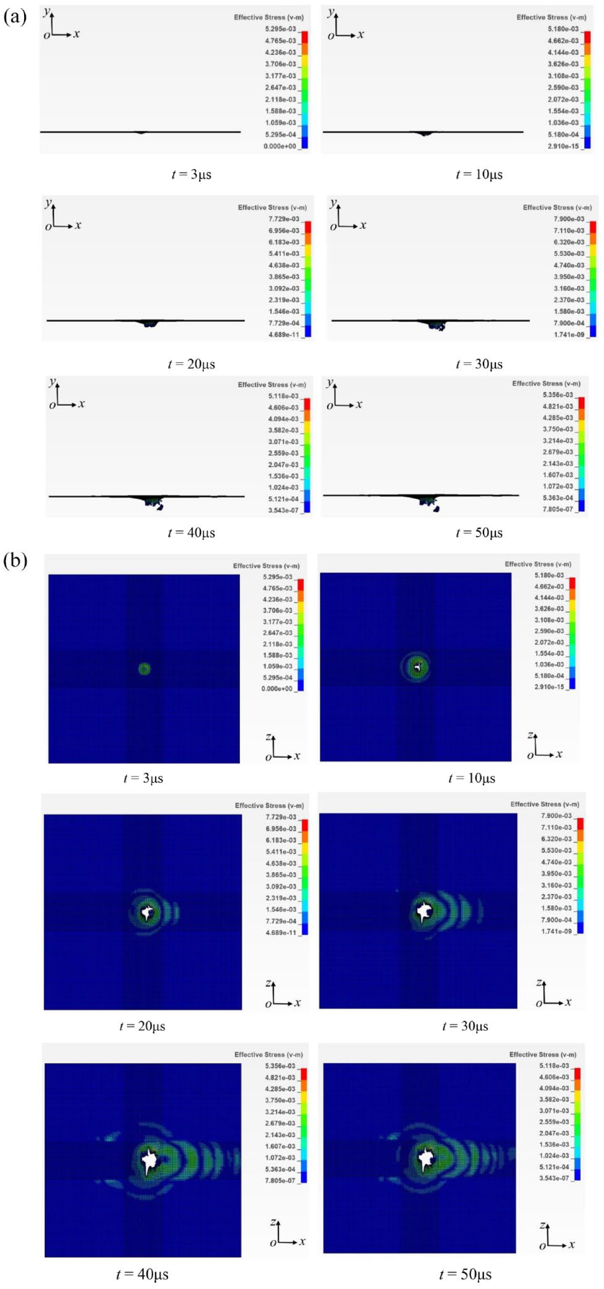
The failure state of the projectile penetrating the second inclined one-way plate at different timepoints: (a) side view and (b) top view.
From the destruction process of the projectile penetrating the second inclined one-way plate, it can be found that when the projectile just contacts the one-way plate, the incident surface of the one-way plate is slightly dented, and a bulge appears on the ejection surface. When the penetration lasts for 10 μs, the stress is transmitted around the bullet point as the center. However, as the penetration continues, the contact area between the projectile and the one-way plate becomes larger, and the stress is transmitted further along the direction of the component velocity of the projectile parallel to the fiber axis. When the projectile progresses to 30 μs, the stress value on the one-way plate becomes larger. After 36 μs, the speed of the projectile body remains basically unchanged, the bullet hole is no longer enlarged, the damage form of the one-way plate is basically completed, and the second inclined one-way slab is completely penetrated.
Comparing the horizontal and inclined one-way plates after penetration, it is found that the failure pattern of the horizontal one-way plate is regular, which is approximately circular, while the failure pattern of the inclined one-way plate is irregular, and the damage along the inclined direction is quite large. In addition, similar to the horizontal one-way plate, the damage area of the incoming surface is also smaller than the damage area of the ejection surface.
Figure 14 is the velocity variation curve of the four 1-way plates when the projectile penetrates the inclined model at a velocity of 272 m/s. The figure shows that the velocity of the projectile will decrease by a certain value every time it penetrates a one-way plate, meaning the kinetic energy of the projectile will be lost every time penetrating a one-way plate. The velocity change of the projectile can be roughly divided into three stages. The first stage is the rapid speed drop stage, in which the curvature of the velocity curve and the speed drop are larger than others. The second stage is the slow speed change section, in which the curvature of the speed curve and the speed drop is small. The third stage is the speed stable section. In this stage, the speed curve reaches the plateau, where the speed is basically stable. When the projectile penetrates the first and fourth horizontal one-way plates, the time slots for the three stages are 0–15, 15–25, and 25–50 μs, respectively. When the projectile penetrates the second and third inclined one-way plates, the time slots for three stages are 0–30, 30–40, and 40–50 μs, respectively.

Velocity time-history curve of projectile penetrating the inclined model of composite material.
Experimental verification of the numerical simulation of composite materials penetration resistance based on fiber inclination model
Ballistic penetration test
Reference standards “GB/T 32493-2016" 20 and “GB/T 32497-2016" 21 design the size of the specimen of 3D woven composite materials in the ballistic penetration test. A total of four square specimens with a size of 150 mm × 150 mm were prepared, numbered 1–4 respectively, as shown in Table 7.
Thickness and mass of composite materials specimens.

The air cannon method was used to carry out the ballistic penetration test of the three-dimensional angle-interlock woven UHMWPEF/epoxy composite material. Figure 15 is a schematic diagram of the ballistic penetration device. By controlling the different ejection speed of the projectile, the remaining speed of the projectile and the damage pattern of the target plate were obtained.

Schematic diagram of the ballistic penetration device.
The three-dimensional composite material ballistic penetration test device (Figure 16) consists of four systems: control system, launch and impact system, velocity measurement system, target chamber and bullet absorption system.

Ballistic penetration test device diagram.
Since it is difficult to determine the trajectory and the coordinate ruler in the same plane, the high-speed camera will produce certain errors when measuring the velocity of the projectile, so the velocity needs to be calibrated. Figure 17 is a high-speed photograph of the projectile traveling. ImageJ software was used to obtain the flight distance and time interval of the projectile, and calculate the incident velocity of the projectile, by measuring the interval of the projectile passing pixels in every 100 frames and the number of pixels per centimeter contained in the coordinate ruler in the figure. The relationship between vlaser and vcamer was obtained as vlaser = 1.1524 vcamer through many experiments, according to which the exit velocity of the projectile captured by high-speed camera was corrected.

Projectile moving image captured by the high-speed camera.
Verification of test results
According to the incident velocity and the exit velocity of the projectile measured, the final failure pattern of the target plate was observed. The reliability of the fiber inclination model established in this paper was verified by comparing and analyzing the residual velocity of the projectile body, the damage shape of the target plate and the numerical simulation results. Table 8 shows the experimental and simulated values of the projectile penetrating the composite target at four different initial velocities.
Comparison of ballistic penetration test and simulation residual velocity.
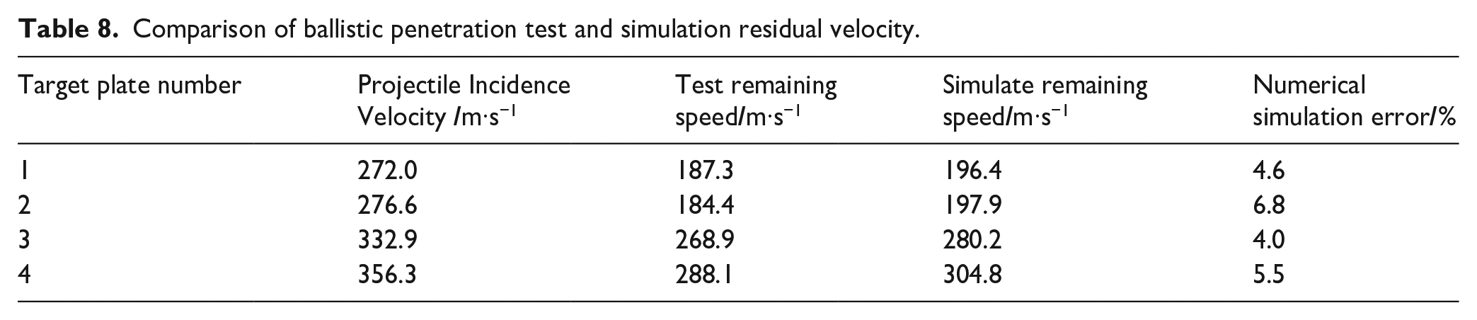
It can be seen from Table 8 that when the incident velocities are 272, 276.6, 332.9, and 356.3 m/s, the errors between the experimental and the calculation results of the remaining velocity of the projectile are all within 7%. Therefore, the numerical simulation results of the residual velocity of the projectile based on the fiber inclination model are in good agreement with the experimental results.
Figure 18 is a comparison between the experimental and simulated calculation results of the residual velocity of the projectile. It can be seen that the relationship between the incident and residual velocity of the projectile is linear, and the experimental value of the residual velocity is slightly smaller than the numerical simulation value. Since the fiber inclination model simplifies the three-dimensional angle-interlock woven composite material into four unidirectional plates composed of fibers and uniformly distributed resin, the complex interactions between the matrix and the fibers in the actual penetration process is ignored. The anti-penetration ability of the target plate to the projectile is reduced, and the experimental value of the residual velocity of the projectile is slightly smaller than the numerical simulation value, indicating that the residual velocity of the projectile predicted by the fiber inclination model is conservative.

Comparison of experimental and numerical simulation values of projectile residual velocities.
Taking the projectile incident velocity of 272 m/s as an example, the damage pattern of the target plate after the ballistic penetration test is compared with the numerical simulation results, as shown in Figure 19. Figure 19(a) is the surface view of the incident surface of the target plate, which shows depressions on the incident surface, and the fibers at the bullet holes are broken and flat. This is mainly because under the huge impact force of the projectile, the surface of the target plate is sheared, causing the fibers to break instantly. Figure 19(b) shows the failure form of the exit surface of the target plate. With the penetration of the projectile, a compressive stress wave is generated in the in-plane direction, which causes the UHMWPEF to be squeezed to produce tensile deformation. Due to the high tensile strength of the fibers, a small part of the fibers are broken, while most of the fibers are deformed and elongated, resulting in the bulges on the exit surface. It can also be found from Figure 19(c) that the fibers near the bullet holes on the exit surface are broken and uneven, and some fibers are pulled out. After the projectile penetrates, the bullet hole on the incident surface of the target plate is small, with a diameter of about 9 mm, while the damage area on the exit surface of the target plate is large, with a diameter of about five times than the bullet hole. Through the comparison between the failure morphology of the penetration test and the numerical simulation of the target plate in Figure 19, it is found that the failure morphology of the specimen is similar to the numerical simulation results.

Comparison of test results and numerical simulation results of target failure form: (a) specimen incident surface, (b) specimen exit surface and (c) specimen side.
Conclusions
Based on CT images, the meso-structural characteristics of 3D corner-interlocking woven UHMWPEF/epoxy composites were analyzed. According to the measured values of meso-structural geometric parameters, the meso-structural model of the composites was established, which was in good agreement with the CT images. The assumption on the yarn morphology is verified, and the calculation formula of the fiber volume fraction in the mesostructure model of the composite material is deduced. The fiber volume fraction of the material calculated by the formula is 49.5%, consistent with the fiber volume fraction of the composite material measured in the laboratory (50% ± 1%), which verifies the correctness of the calculation formula of the fiber volume fraction in this study.
The mechanical property parameters of the unidirectional plate in the fiber inclination model are calculated according to the classical composite laminate theory, and the fiber inclination model of the composite material is established. Four groups of projectile penetration tests with different incident velocities were carried out, and a comparative analysis was performed on the numerical simulation of the penetration of the composite material structure by the fiber inclination model. The simulated values of the residual velocities of the projectile are in good agreement with the experimental results, with an error within 7%. The projectile incident velocity and the residual velocity are roughly linear, which indicates the accuracy of the method to study the penetration problem by simplifying the complex mesostructure of the composite material by the fiber inclination model.
Under the penetrating of the projectile at 272 m/s, the incident surface of the composite target plate was damaged by shearing, showing a concave shape, and the fibers were broken and flat. The exit surface was mainly manifested as tensile failure and with the pull-out of some fibers, most of which were greatly deformed, and a bulge formed on the exit surface. When the “fiber inclination model” was penetrated by the projectile, the failure patterns of the one-way plates in different postures were quite different. The failure form of the horizontal one-way plate was regular and similar to the original shape, while the failure form of the inclined one-way plate was irregular, with a larger damage along the inclined direction, but the damage area of the incident surface of the horizontal and inclined one-way plate was smaller than that of the exit surface.
Through the comparison between target plate failure shape of the penetration test and the numerical simulation, it is found that the failure shape of the specimen is in good agreement with the numerical simulation results. However, a fiber pullout phenomenon was observed in the real penetration failure, in addition to fiber tensile failure and matrix breakage, mainly due to a simple numerical simulation on the failure mode of the one-way plate.
Footnotes
Declaration of conflicting interests
The author(s) declared no potential conflicts of interest with respect to the research, authorship, and/or publication of this article.
Funding
The author(s) received no financial support for the research, authorship, and/or publication of this article.