
Abstract
The new three-dimensional angle-interlock woven UHMWPEF/epoxy composite was prepared by the VARIM method, and its mechanical properties were studied. Specifically, quasi-static and dynamic compression tests were carried out by universal testing machine and split Hopkinson pressure bar (SHPB) apparatus. Stress-strain curves under the quasi-static and high strain rates (800, 1000, 1400, and 1600 s−1) reveal the destructive characteristics of the composite material. The results indicate that the UHWMPEF/epoxy composite is a strain rate sensitive material and shows different levels of sensitivity at various strain rates. In the quasi-static compression test, when the strain rate was increased from 4.2 × 10⁻⁴ to 1.4 × 10⁻³ s−1, the failure load and ultimate strength increased by about 19.1% and 20.1%, respectively, and the failure strain and specific energy absorption decreased by about 1.53% and 6.1%, respectively. In the dynamic compression test, when the strain rate increased from 800 to 1600 s−1, the failure load and ultimate strength increased by about 16% and 15.9%, respectively, and the failure strain and specific energy absorption decreased by about 64.7% and 60.3%, respectively. The failure fracture surface of the specimen under quasi-static compression was at an angle of 40°–45° with the load direction. The matrix fragmentation at the fracture was obvious, and the warp fiber bundle was broken and peeled off from the matrix. The damage of specimen under dynamic compression develops quickly and the deformation process is short, which shows a relatively symmetrical shear fracture failure morphology.
Keywords
Introduction
Three-dimensional textile composite materials, which have multiple types such as laminated, weaving, knitting and weaving, are widely used in protection engineering, shipbuilding and the automotive industry and other fields due to their advantages of light weight, good damage durability, high specific modulus and strength, high damage tolerance and energy absorption rate, and good impact and fatigue resistance. The different spatial structures of each type make their performance different. Scholars all over the world have carried out significant research on three-dimensional textile materials with substantial results.1–3 For example, Song et al. 4 investigated the failure mode and dynamic compression mechanical properties of carbon fiber/epoxy composites, analyzed their in-plane and out-of-plane compression failure morphologies, obtained the stress-strain curve of carbon fiber/epoxy laminates, and pointed out that the material has a strain effect. Zhang et al. 5 conducted impact compression tests on the three-dimensional four-step braided composite material in both directions inside and outside the plane. Test results showed that the compression stiffness of the material increases linearly with the strain rate and, the maximum stress, showing obvious strain rate sensitive characteristics. Zhang et al. 6 studied the effects of temperature and strain rate of three-dimensional carbon fiber/epoxy composites on their impact compression performance. The results showed that shear deformation is the main failure mode of the material under high temperature and high strain rate, and the material compression performance increases with strain rate, and decreases with temperature (23–210°C). Shim et al. 7 used Hopkinson rods to perform high-speed tensile tests on aramid fabric samples, studied the dynamic mechanical properties of the fabric, and determined the load-deformation curve and failure characteristics of the fabric under different tensile rates. It shows that the tensile strength and modulus of the aramid fabric increase with the strain rate, which has a high degree of strain rate correlation. At the same time, the aramid fabric sample also fails in a more brittle manner in response to the increasing strain rate. Mohanlal 8 prepared different fiber composite materials with basalt and carbon fiber as the reinforcement and vinyl ester as the matrix, and conducted quasi-static tests of tensile and bending on the composite materials. The results show that the tensile and flexural strengths of the material increase with the load and temperature during the curing process, and the curing time has no significant effect on the mechanical properties of the material. Littell 9 studied some defects of the previous triaxial braided composites and designed a new test method to accurately quantify the performance of the triaxial braided composites. A micro-macro material mechanics model was established based on the experimental data, and the mechanical response of the composite material under static load and ballistic impact load was simulated. The research results show that the developed material mechanics model predicts the static strength and stiffness of composite materials with an error of less than 10%. Liu et al. 10 conducted tensile tests on several three-dimensional woven composite materials to explore the strain of the materials. The research shows that the addition and subtraction of the binding warp yarns retain the tensile strength and the integrity of the modulus of the specimen to a certain extent. Yang and Li 11 conducted a series of mechanical tests along different directions on carbon fiber corner interlocking woven composites with four structures. The research shows that the material properties of carbon fiber corner interlocking woven composites are orthotropic, and the relationship between the basic mechanical properties and modulus is maple leaf shape. Guo et al. 12 designed three 3D woven carbon fiber composites with different structures, and studied the tensile properties of the materials in different directions. The research shows that the fabric structure is an important factor affecting the macroscopic mechanical properties of composites. With the increase of the volume fraction of twill yarn, the tensile strength and modulus of the material in the warp direction decreased, while the tensile properties in the weft direction increased. Zhang 13 studied the effect of fabric structure and thickness on the penetration resistance of UHMWPE composite laminates. The research shows that unidirectional composite laminates have higher ballistic limit speed and energy absorption capacity, and the ballistic limit speed has a bilinear relationship with the material thickness. Most of these studies are based on laminated or four-step three-dimensional weaving carbon fiber/epoxy composites. Ultra-high molecular weight polyethylene fiber (UHMWPE) has low density, strong tensile properties and excellent energy absorption characteristics. The angle interlocking structure introduces binding warp yarns in the Z direction. It overcomes the weaknesses of no connection, easy delamination, and low strength between the plane fabric layers. In light of the above reports, one can tell that the research on the UHMWPE fiber woven angle interlocking structure as a reinforcement composite material is rarely reported. Therefore, the in-depth research on the compressive properties of the new type 14 three-dimensional angle interlocking UHMWPEF/epoxy woven composites material is of great significance. In this paper, the vacuum assisted resin infusion molding method (Vacuum Assisted Resin Infusion Molding, VARIM)15,16 was used to prepare the new composite material. Through loading tests, the failure characteristics of the new three-dimensional angle interlocking woven composite material were analyzed. By studying the static and dynamic mechanical performance parameters, the damage mechanism of the material was obtained. Based on the results, the mechanical properties of the material were summarized.
Material preparation
Material composition
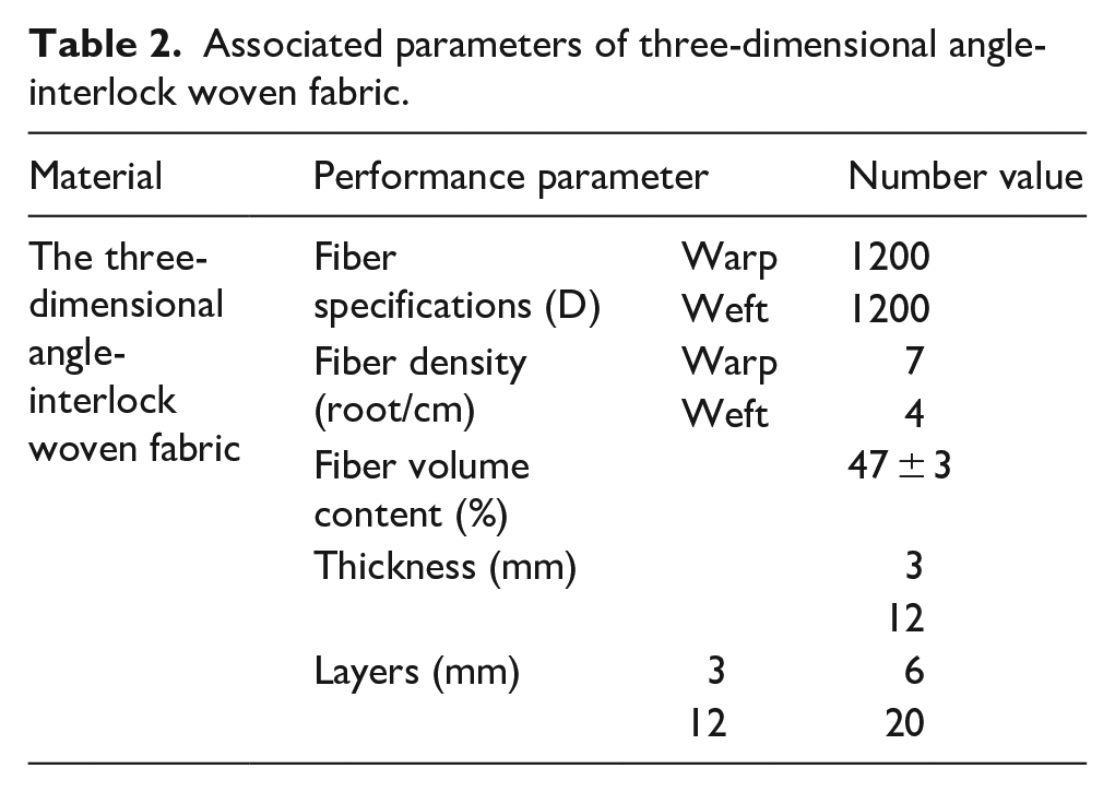
Ultra-high molecular weight polyethylene fiber (UHMWPEF) is used in the composite material, with the single fiber bundle specification of 1200 D. The performance parameters are shown in Table 1. The associated parameters of the 3D warp interlock fabric architecture are shown in Table 2. The resin matrix material is cured by IN2 epoxy diversion resin and AT30SLOW slow resin curing agent, and the performance parameters are shown in Table 3.
UHMWPE fiber performance parameters.

Associated parameters of three-dimensional angle-interlock woven fabric.
Performance parameters of resin matrix.

Material preparation
The vacuum assisted resin flow molding (VARIM) process (Figure 1(a)) was used to cure the epoxy resin and the corner interlocking ultra-high molecular weight polyethylene fiber bundle fabric (Figure 1(b)) into a fiber resin composite material, as shown in Figure 1(c).

(a) Vacuum diversion, (b) fabric samples, and (c) composite material sample.
Analysis of the internal structures of the material
Figure 2(a) shows the cross-sectional image of the warp yarn and weft yarn through the material CT tomogram. It can be seen that the wefts are arranged in parallel and aligned in the thickness direction, and the binding warps are inserted into the gaps of the multi-layer weft yarns and arranged crosswise with the wefts at a certain angle in the thickness direction to form a complete angular interlock. The gap between the weft yarns is determined by the weft yarn density. Figure 2(b) shows the spatial structure model of the angle interlocking woven material established by the modeling software TEXGEN.
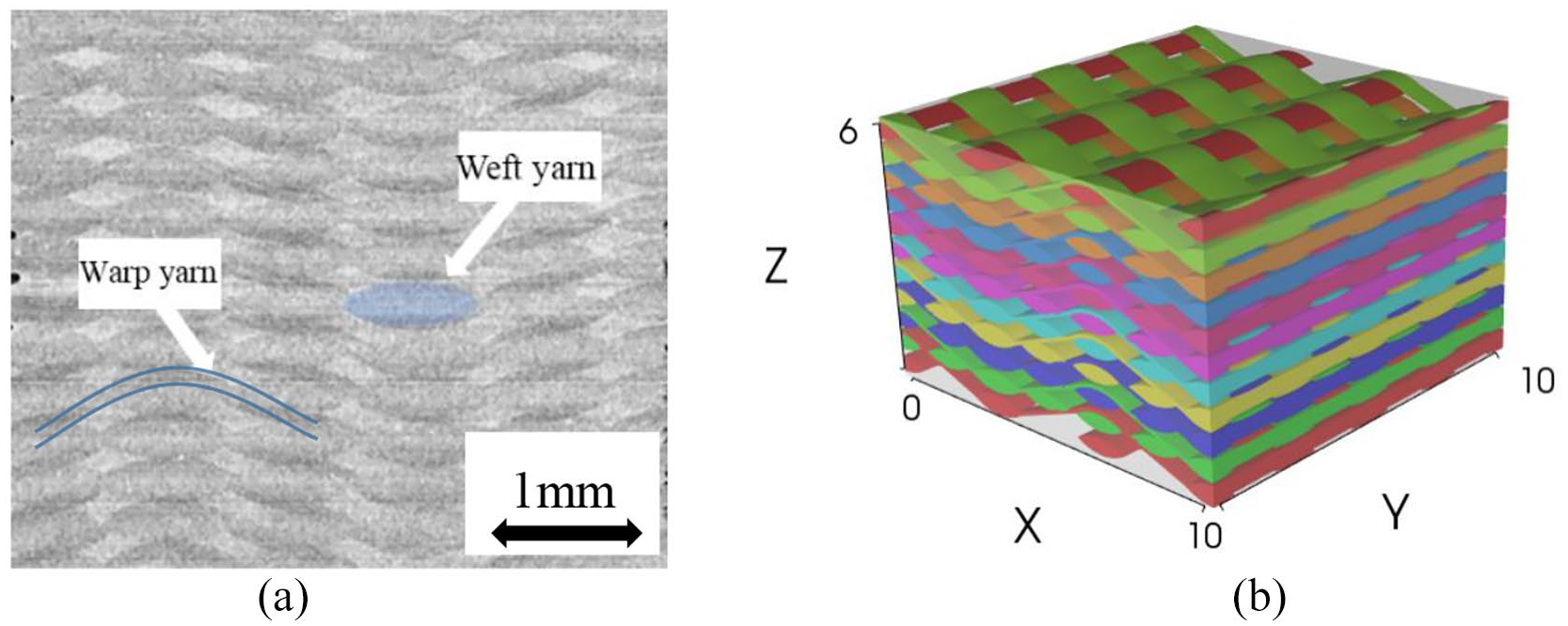
(a) Sectional view of CT scan and (b) TEXGEN space mode.
Quasi-static compression test
Specimen design
UHMWPEF/epoxy composite material quasi-static compression test piece is designed in accordance with GB/T1448-2005, 17 as shown in Table 4.
Quasi-static compression test specimen.

The written code speckles are applied to the surface of the specimen using water transfer printing technology. Figure 3 shows the appearance of the specimen before and after speckle printing, in preparation for the subsequent analysis of the compression deformation of the specimen.

Comparison of specimens before and after coating and printing speckle: (a) before smearing speckle and (b) after smearing speckle.
Test plan
The universal testing machine was used to carry out the quasi-static compression test of the material, as shown in Figure 4(a), at the strain rates of 1.4 × 10⁻³ and 4.2 × 10⁻⁴ s−1. The test piece was measured and analyzed, as shown in Figure 4(b).

(a) Placement of test pieces and (b) DIC image processing.
Analysis of test results
Under quasi-static compression, the fiber in the matrix of the composite material is broken and delaminated. The cracks in the matrix or on the interface are used as the basis for the failure of the material.
Figure 5(a)–(c) are the stress-strain curves of specimens with different shapes and sizes at the strain rates of 1.4 × 10⁻³ and 4.2 × 10⁻⁴ s−1. The failure states of the specimens are very similar. The stress-strain curve shows a slow upward trend at the initial stage of load application, and resin matrix expands along the lateral direction and deformation increases. At this time, the bonding force between the resin and the fiber contact surface in the warp and weft directions resists the lateral distortion. When the load reaches 28.6% of the ultimate strength, the upward trend of stress-strain curve has increased significantly as the load increases further, which indicates that this material has a compaction effect. That means the fiber structure is gradually compacted, and the matrix begins to crack and break. As the warp fibers are in curve shape, it has little hindrance to the breaking and cracking of the matrix, so the shear resistance is weak, and the warp is gradually drawn into a straight line as the matrix deforms. However, the weft fibers arranged in parallel and straight lines have greater adhesion to the resin matrix, which makes the shear resistance much greater than that of the warp direction. Thus, the stress-strain curve shows an approximately positive proportional growth trend. Finally, the stress-strain curve drops sharply and the specimen is fractured obliquely along the meridian as the load increases. As can be seen from Figure 5(a) and (b), when the thickness of the specimen is fixed and the section shape is the same, the failure strain of the material increases greatly with the increase of the force area, but the ultimate strength does not change significantly. It can be seen from Figure 5(b) and (c) that the cross-sectional shape hardly affects the ultimate strength and failure strain of the material when the thickness of the specimen is fixed and the force area is similar. As is shown in Figure 5(a)–(c), one can see that when the strain rate increases, the failure strain of the material decreases, and the ultimate strength increases slightly.

Compressive stress-strain curve for: (a) 20 mm cuboid, (b) 14 mm cuboid, and (c) 15 mm cylinder.
Due to the weak warp shear resistance of the composite, shear failure of the specimen is along the meridional slope (the angle between the load application direction and the fracture surface is about 40°–45°). Moreover, a large number of fiber bundles peel off from the matrix that is obviously broken. The fibers are slightly delaminated, of which the warp fibers are broken, as shown in Figure 6.

Typical compression failure characteristics for: (a) specimens LF1 and (b) specimen LF2.
As is shown in Figure 5(a) and (b), at the same thickness, the ultimate strength of 14 mm rectangular body is slightly lower than that of 20 mm one, and the failure strain decreases even more. By comparing Figure 5(a)–(c), it can be seen that the three specimens have strain-rate effects and the growth trends of stress-strain curves are approximately the same. As the vertical compression deformation increases, the stress-strain curve shows a significant non-linear relationship. In Figure 5(b), by comparing the stress-strain curves at different strain rates, one can see that the failure strain and ultimate strength of the material do not change significantly with increasing strain rate in the same order of magnitude. However, when the strain rate increases by an order of magnitude, the failure strain of the material decreases, while the ultimate strength rate does not increase significantly. As can be seen from Figure 7(a) and (b) and Table 5, the cross-sectional areas of the 7.5 mm radius cylinder and 14 mm rectangular body are similar, the failure strain and ultimate strength of the two specimens are close to each other, and the stress-strain curves match. Therefore, the bearing capacity of the cylinder is larger than that of the rectangular body. At the same strain rate, when the cross-sectional area of the specimen is doubled, the strain at the time of damage increases by 20.2% and the energy absorption capacity of the specimen increases by 24%. However, the cross-sectional area and shape of the specimen have little effect on its ultimate strength. The differences between the ultimate strengths, failure strains, and energy absorption capacities of the three specimens are within 1%.

(a) 1.4 × 10⁻³ s−1 stress-strain curve and (b) 4.2 × 10⁻⁴ s−1 stress-strain curve.
Quasi-static compression mechanical performance parameters.

Dynamic compression test
Test plan
The dynamic compression test was operated on a SHPB apparatus as shown in Figure 8. The system consists of five systems, including launch system, impact system, guidance, and support system, data processing system, camera and speed measurement system, as shown in Figure 9. Referring to Hopkinson Bar Techniques, 18 the specimen is made into a cylinder (DH) with d = 8.5 mm and h = 3.5 mm, whose deformation and damage of the specimen are observed and recorded by a high-speed camera. The strain rate of the dynamic compression test in our study was set to 800, 1000, 1400, and 1600 s−1.

SHPB system.

Schematic diagram of SHPB device composition.
The test is based on the two basic assumptions. One assumption is that the stress wave transmitted on the transmission rod and the incident rod is a one-dimensional elastic wave. Another assumption is that the strain and the stress generated by the specimen after an impact load is uniform along the length. 19 The stress, strain, strain rate equations are deduced as follows.


Where

(a) Specimen DH and (b) specimen installation.
Analysis of test results
Under dynamic compression, the failure of the material lies in whether the material structure is complete or large deformation occurs, the fibers in the matrix are broken and delaminated, and the fractures and defects are generated inside the matrix or on the interface.
It can be seen from Figure 11 that the dynamic stress-strain curve at each strain rate shows a non-linear behavior, which can be roughly divided into four stages. At the initial stage when the transmission rod receives the stress wave, the voids, and defects in the specimen begin to be compacted, so the curve shows a concave upward trend. After the specimen is gradually compacted, the fiber matrix bears the load together, showing an approximately linear curve at this stage. Afterward, the deformation further expands, and the specimen begins to yield without gentle yielding platform, so the curve has a sunken trend at this stage. Finally, the specimen is damaged and broken, and brittle and plastic deformation occurs, which is marked by the ultimate yield strength in the curve.

Stress-strain curves of DH specimens under different strain rates.
Figure 12 shows the strain rate curve can be divided into three stages, including rapid rise, slow rise, and fall to a certain value. It is because the contact area and compression stiffness of the specimen and rod increase gradually with the increase of deformation in the thickness direction due to the influence of dynamic impact.

The strain rate curve of the DH specimen in the whole field.
Through comparative analysis of the high-speed impact images (Figures 13 and 14) and the stress/strain-time curve (Figures 15 and 16) of the specimens, it is found that the damage and destruction of the specimens all occur in the rapid stress drop section, which is independent of the strain rate. For the specimen at the of strain rate 1600 s−1, the stress on the specimen increases sharply during 0–18 μs, where the internal pores and defects of the material are compacted and the matrix and fibers are stressed as a whole. There is no obvious damage on the outside of the specimen but macroscopic invisible damage inside. After the specimen reaches the ultimate stress in about 18 μs, it deforms, expands, and destabilizes during 18–35 μs, during which time the matrix is broken and fractured, accompanied by fragments flying out, the stress droppings sharply, and occurrence of macroscopic shear failure. After 35 μs, the specimen is severely damaged, where the stress drops slowly with a low bearing capacity, showing a failure state. At the strain rate of 1400 s−1, the specimen reaches the ultimate stress in about 24 μs, which means the bearing time increases. The second stage corresponds to 24–44 μs, and the bearing time increases too, which indicates that the time for the specimen to experience damage decreases as the strain rate increases. At low strain rate, the impact speed is slower, the time for the specimen to reach the ultimate stress and failure strain increases, and the absorbed energy increases, which can slow down the cracking of the resin matrix and the delamination of fibers. On the contrary, the impact velocity increases at high strain rate, the specimen reaches the ultimate stress faster and the deformation develops rapidly, and shear failure occurs in a very short time with the separation of matrix fragments.
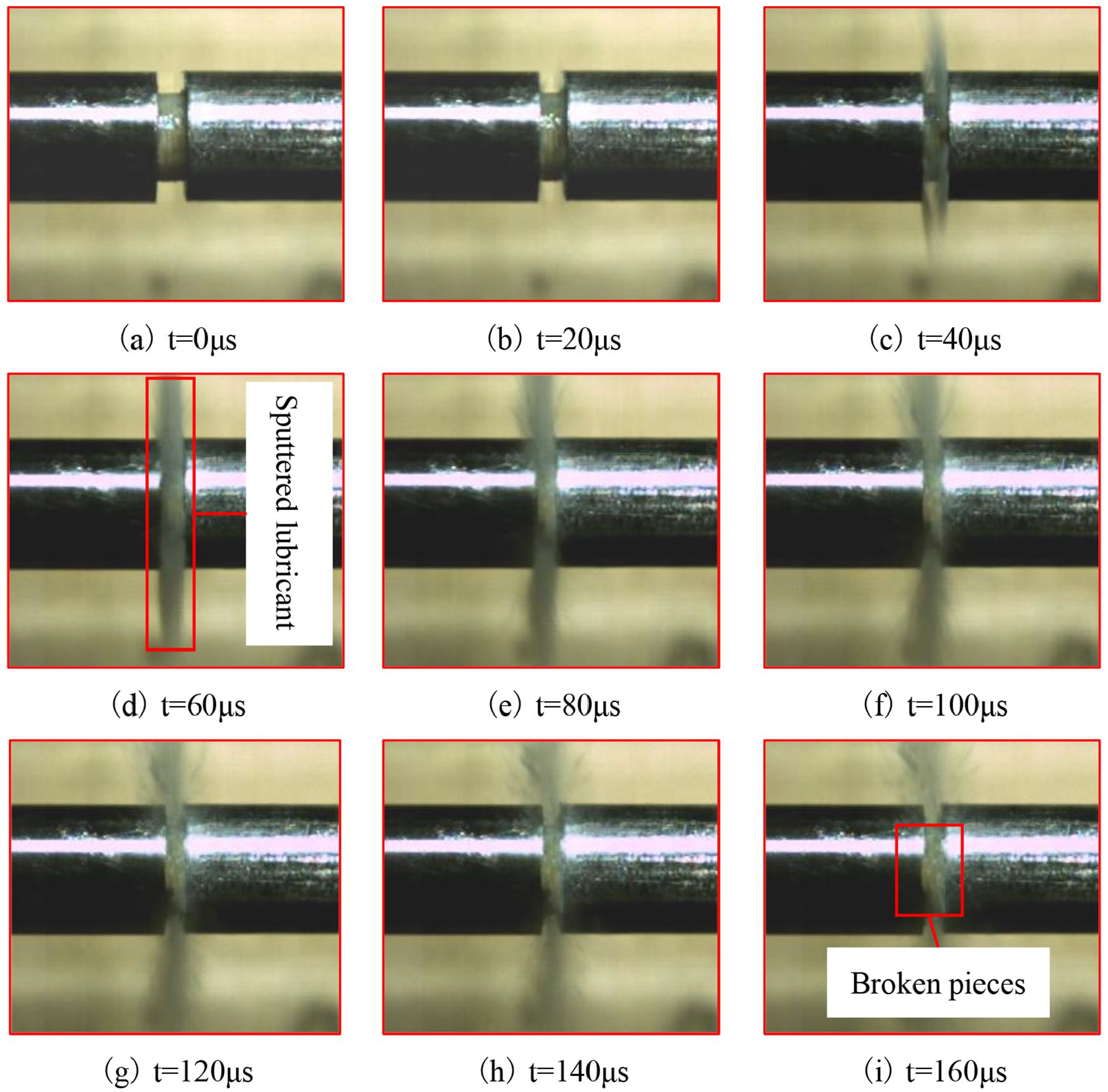
High-speed impact diagram at 1600 s−1 strain rate.

High-speed impact images at 1400 s−1 strain rate.

1600 s−1 stress/strain versus time curve.

1400 s−1 stress/strain versus time curve.
The impact failure mode of the specimen under different strain rates is shown in Figure 17. The whole specimen is squashed at the strain rate of 1600 s−1, showing symmetric shear fracture damage. The edge of the impacted surface fractures and separates along the weft direction, the weft yarn is flattened, and the warp yarn is broken. On the back side of the impacted surface, small fragments are broken along the warp bending direction at both ends of the warp yarn direction. Shear cracks are produced along both sides of the load impact direction and expand along the direction of the binder warp yarns. This crack passes through the multi-layer weft yarn with the increase of strain rate. At the strain rate of 1400 s−1, the specimen has a large lateral expansion and obvious vertical deformation. Cracks are generated along the bending direction of the warp yarn, and there is shear-broken matrix at both ends of the cross-section without detaching. At the strain rates of 800 and 1000 s−1, the specimen deforms and the expansion trend is similar to the previous two stages, with no obvious macroscopic damage but only some minor cracks.

Impact failure mode of specimens under different strain rates.
Comparative analysis of quasi-static and dynamic compression tests
It can be seen from Table 6 that the ability of the specimen to absorb energy is related to the magnitude of the applied strain. Compared to the case at the strain rate of 4.2 × 10⁻⁴ s−1, the ultimate strength of the specimens at the strain rates of 800 and 1000 s−1 increases by about 21.3% and 23.1%, respectively, the failure strain reduces by 4.24% and 5.51%, respectively, and the specific energy absorption reduces by around 36.5% and 52.1%, respectively. The ultimate strength of the specimen at the strain rate of 1600 s−1 greatly improves by about 40.7% compared to that at the strain rate of 4.2 × 10⁻⁴ s−1, the failure strain reduces by 7.66%, and the specific absorption reduces by about 74.2%. Compared with the case at the strain rate of 1.4 × 10⁻³ s−1, the ultimate strength of the specimen under the strain rate of 800 and 1000 s−1 only increases by about 1%−2%, and the failure strain reduces by 2.71% and 3.98%, respectively, and the specific energy absorption reduces by about 32.4% and 48.9%, respectively. Compared with the case at the strain rate of 1.4 × 10⁻³ s−1, the ultimate strength of the specimen under the strain rate of 1400 s−1 increases by about 11.5%, the failure strain reduces by 5.45%, and the specific energy absorption reduces by about 63.2%.
Mechanical performance parameters of specimens under different strain rates.

It can be seen from Figures 11 and 18 that the composite material may have defects such as pores and small cracks during the weaving and curing process. Stress grows slowly in the rising phase and rebound in the falling phase, and the trends of the curves are different when they reach the stress peak. Figure 18 shows that at high strain rates, the impact speed is faster, and the damaging and the softening time of the specimen is shorter during the stress-raising stage. Thus, the specimen compresses quickly and then reaches the ultimate strength of the material at a lower strain. On the contrary, at a low strain rate, the impact speed is slower, and the damaging and the softening time of the specimen is longer during the stress-raising stage. In this condition, the ultimate strength is significantly lower than that of the material at high strain rate, which has a certain strain rate effect.
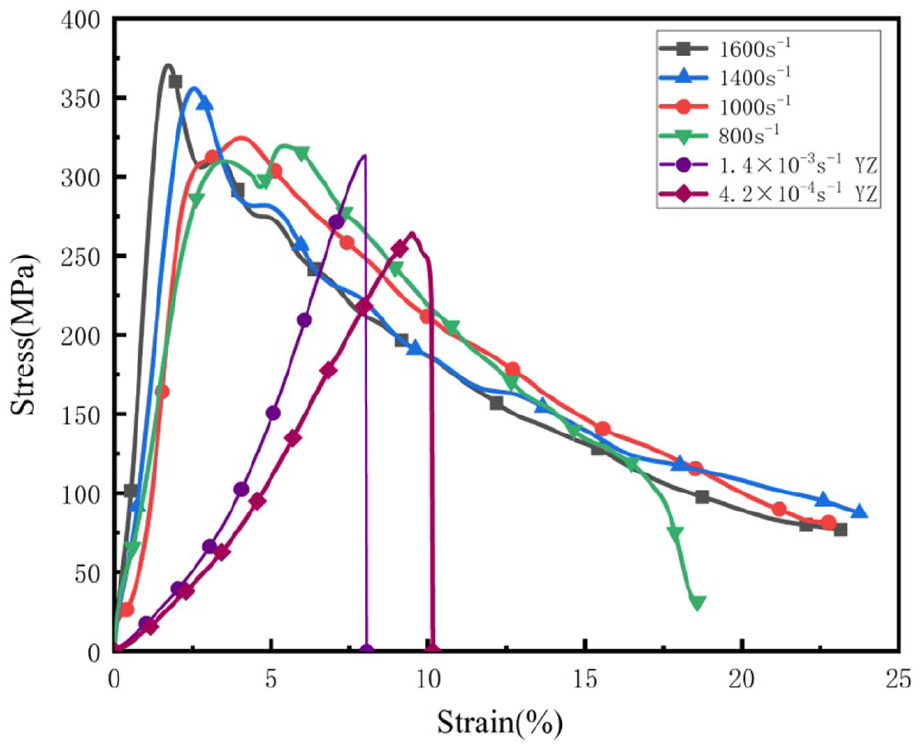
Comparison of quasi-static and dynamic stress-strain curves.
Conclusion
The new type of three-dimensional angle interlocking woven UHWMPEF/epoxy composite material is prepared by the VARIM method. The quasi-static and dynamic compression tests were carried out to study the mechanical properties, failure characteristics, and damage mechanism of the material. Several conclusions are summarized as follows.
The new three-dimensional angle-interlock woven UHWMPEF/epoxy composite material has significant compaction effect under quasi-compression compression, but the compaction effect is not obvious under dynamic compression.
The compression failure of the new three-dimensional angle-interlock woven UHWMPEF/epoxy composite material under quasi-static is shear failure. A large number of fiber bundles are peeled off from the matrix, the matrix fragmentation at the fracture is obvious, and the warp fiber is broken.
Under quasi-static compression, when the strain rate is increased from 4.2 × 10⁻⁴ to 1.4 × 10⁻³ s−1, the failure load and ultimate strength of the new three-dimensional angle-interlock UHWMPEF/epoxy woven composite material increase by about 19.1% and 20.1% respectively, and the failure strain and specific energy absorption decrease by about 15.9% and 6.1%, respectively. When the applied strain rate is constant and the cross-sectional area is doubled, the material breaking strain increases by about 20.2% and the specific energy absorption increases by 24%.
The dynamic compression failure of the new three-dimensional angle-interlock woven UHWMPEF/epoxy composite material is mainly shear instability which is symmetric through crack failure. The edge of the impact surface is separated along the weft direction, and the weft yarn is squashed. The warp yarn is in a broken state, and the impacted back has small fragments breaking along the warp direction at both ends of the warp direction. Along the direction of load impact, shear cracks are generated on both sides and extend along the direction of binder warp yarn, and the crack pass through multiple layers of weft yarns as the strain rate increases.
Under dynamic compression, when the strain rate of the new three-dimensional angle-interlock woven UHWMPEF/epoxy composite material is increased from 800 to 1000 s−1, the ultimate strength only increases by 0.9%, and the specific energy absorption reduces by 24.5%. When increased from 1400 to 1600 s−1, the ultimate strength increases by 3.6%, and the specific energy absorption decreases by 27.2%. The failure strain and specific energy absorption of the material at 1600 s−1 strain rate are only about 35% and 40% of those at 800 s−1 strain rate.
The change of the cross-sectional shape of the new three-dimensional angle-interlock woven UHWMPEF/epoxy composite material has little effect on its compression performance, while the size of the cross-section has a greater impact. The composite material has strain-rate effects under quasi-static and dynamic compression, and it exhibits different levels of sensitivity under high and low strain-rates.
Footnotes
Declaration of conflicting interests
The author(s) declared no potential conflicts of interest with respect to the research, authorship, and/or publication of this article.
Funding
The author(s) received no financial support for the research, authorship, and/or publication of this article.