
Abstract
Aiming at the problem that the existing rope falling device can only detect the impact force and cannot synchronously detect the impact displacement, this paper introduces a large-range high-precision displacement sensor and constructs a rope impact force-displacement detection device. Taking the nylon kernmantle rope for high-altitude fall protection commonly used in aerial work and rock climbing as the research object, the impact response behavior of the rope when drop mass is dropped once and repeatedly is systematically studied, and the impact force and impact displacement are discussed. Further, the evolution of the elastic modulus of the rope is discussed and this could provide theoretical support for the design of the impact-resistant rope structure and the rope impact protection.
Introduction
With the development of society and the improvement of people’s living standards, fiber ropes have played an increasingly important role in many fields.1 –4 On the one hand, more and more people are beginning to try exciting sports such as rock climbing, tree climbing, bungee jumping, and skydiving. In these activities, people experience the joy brought by height and impact, but safety accidents often occur. After these accidents, ropes have become a big problem. On the other hand, with the rapid development of high-performance fibers and the continuous improvement of rope braiding technology, chemical braided ropes have lightweight, high strength, high modulus, low creep variable, temperature resistance, corrosion resistance, and other properties, making it widely used in industrial production and other fields,5 –10 people use a large number of chemical fiber braided ropes as life protection ropes in high-altitude operations, emergency rescue, and aerospace, as shown in Figure 1.

Cases of rope impact in different fields.
In these processes, the fiber rope acts as a lightweight, flexible energy-absorbing, and impact-absorbing device. 11 Taking the anti-fall kernmantle rope for mountain climbing as an example, when the rope is impacted, the rope is required to have sufficient strength to withstand the impact force and ensure the safety of the falling person. The rope is required to have sufficient strength. The rope can be elongated enough to reduce the impact force generated during the impact and ensure that the falling person will not receive secondary injury due to the huge impact force from the rope. Other application conditions also have similar requirements. On the one hand, the strength of the rope is required to be large enough, and on the other hand, the strength should not be too large, resulting in damage to the connection parts or personnel due to excessive impact force.12,13 Therefore, it is required that the rope should not only have increased strength but also have appropriate elasticity to ensure sufficient energy absorption. Therefore, it is important to study the impact response behavior of this type of rope during the impact process to understand the parameters such as the maximum impact force, impact elongation, and impact modulus of the rope during the impact process.
In the early days, researchers studied the mechanical response behavior of the rope to the impact by comparing the static tensile fracture energy and the rope impact energy. Newman and Wheeler 14 used a self-made impact device to study nylon rope and natural fiber sisal rope for impact tests, and the energy value calculated by static test gave a safe estimate of rope performance under impact load. Schiefer et al. 11 calculated the energy required to break the yarn through the impact load and static load. In general, the impact energy to break can be estimated from the static energy, and the impact energy of low elongation yarns greatly exceeds the static value. Attaway and Weber 15 proposed a new formula for predicting the maximum impact force of the rope based on the force-deflection relationship of the rope during the impact process. An experimental analysis by Attaway and Weber 16 found that modeling the rope as a spring yields a generally accepted way of analyzing impact forces, and the force predictions of the equations are quite accurate. However, as the test weight and drop coefficient increased, the force predictions of the equations became significantly inaccurate. Richard Goldstone used the spring as the factor to analyze the impact force of the rope and concluded that the impact size of the rope is only related to the fall coefficient. The UIAA international mountaineering organization 17 only meets the requirements for the protection of conditional mountaineering and rock climbing when the climbing rope meets the requirements of five falls in the number of falls, and there is no requirement for the rope itself to change during the fall of the rope. 18 Emri et al. 19 proposed a new method based on a simple non-standard drop weight experiment and developed a method to predict the impact force, the viscoelastic-plastic deformation of the rope, the energy stored, recovered, and dissipated during rope handling and The method of changing rope stiffness within each loading cycle. Nikonov et al. 13 evaluated the influence of humidity on rope performance based on the experimental method of Sry et al.20,21 developed an impact testing machine using a falling weight to apply five consecutive impact loads to a pre-tensioned rope to evaluate the stiffness corresponding to the first impact-rebound load portion of each drop and proposed an empirical equation to estimate the rope stiffness after any preload treatment. This equation is used to determine the preload treatment conditions to stabilize the stiffness of the braided rope before it is used in the engineering field. The spring-damper model was then used to estimate the tensile behavior of the rope under drop massing and to study its strain. 22 The results of the spring-damper model are in good agreement with the experimental data. Using this model, the delay time between stress and strain can be estimated. Chu23 studied the impact load of mooring rope caused by relaxation and tension of the mooring system of a deep-sea platform and concluded that the maximum tension in the rope increases with the increase of platform mass, external excitation, and pre-tension increase and decrease as the length of the rope increases.
The above studies are less concerned with the overall impact response of the rope in a single drop impact, and also less about the change law of the rope response when the rope is impacted by the fall to the point of failure. This subject designs a synchronous test device for the impact strength and impact elongation of the rope and uses a high-precision method to measure the elongation change and force of the rope, which fills the gap in the lack of deformation data in previous scholars’ related research. At the same time, the process of the rope from the first impact to multiple impacts until the entire fracture process is completely carried out, and the evolution law of mechanical parameters of the rope under the action of multiple impacts is studied.
Experimental material and impact device
Experimental rope material and structure
The structure of the nylon kernmantle rope used in the experiment is shown in Figure 2. The core of nylon kernmantle rope consists of 12 parallel three-strand twisted ropes, of which six are S-twisted and six are Z-twisted. The sheath is braided by 48 strands of nylon rope with a 1:1 pattern. The rope was manufactured by Qingdao Huakai Marine Technology Ltd. The breaking strength (MBL) of the rope is 30.2 kN, and the breaking strength of the Figure 8 knot is 17.8 kN. The linear density of the kernmantle rope is 68.6 g/m (Table 1).

Rope and knotting for impact test, (a) shows the tested rope with 12 cores of three-strand twisted rope arranged in parallel, (b) shows an eight-knot at both ends, (c) shows the front of the eight-knot, and (d) shows the back of the eight-knot.
Material properties of braided nylon kernmantle ropes.

Impact force-impact displacement synchronous impact test device
In this paper, a continuous drop impact test apparatus as shown in Figure 3 was developed for rope impact testing. The device contains eight main components. The first part is the test frame. The frame includes the installation parts of various sensing devices, which play a fixed role, and the frame will not be plastically deformed during the impact process. The second is the rope lifting motor, which is installed at the top of the impact test frame. It is driven by the motor to connect the steel wire rope to the drop mass, and the wire rope is wound to lift the drop mass to the specified height. The third part is the LRT-TB5000 displacement sensor, the response time is 1 ms, the detection distance is 60–5000 mm, and the detection accuracy is 0.1 mm. It is installed on the top of the drop mass, and the laser sensing device measures the fall height of the impact load vertically downward.

The construction of the impact test device.
The fourth part is the electromagnetic release device. The electromagnetic release device is installed at the connection point between the coiled wire rope and the drop mass. When the wireless device sends a release signal, the electromagnetic release device releases the drop mass and causes it to fall to produce an impact load. The fifth part is the LX-002 strain transducer device, the force range is 0–50 kN, and the measurement accuracy is 0.1 N. One end of the sensing device is connected to the drop mass and the other end is connected to the test rope. The sixth part is the impact guide device. The impact guide device is installed in the middle of the left and right sides of the experimental frame as a guide rail and cooperates with the pulley to ensure that the drop mass is vertically downward during the fall. The seventh part is drop mass. Many iron plates are loaded on the load frame, 2 and the quality of the impact load is controlled by controlling the number and quality of iron sheets. The eighth part is the buffer device, which is to slow down the impact of the impact load on the ground when the rope breaks and fails during the impact process. The ninth part is the specific parameter accuracy of the signal amplifier LX-FD-CF so that the output signal voltage reaches 0–10 V and can be successfully collected and written into the computer by the data acquisition equipment, among which the data acquisition equipment is the National Instruments data acquisition card USB6008. The tenth part is the data acquisition part. The data acquisition mainly collects the voltage signals generated by the sensor and the distance sensor and reads and records the data through LabVIEW.
Experimental procedure
Impact test by releasing 1000 N impact load from 5.2 m. The shock test was performed with a fall coefficient of 1. In order to simulate the rope as a protective safety rope, the initial rope is added without any pretreatment, and the two ends of the rope are used, as shown in Figure 2(c) and (d). The natural elongation length of both ends of the rope joint is 2 m, and the rope falls n times until the rope breaks and fails. To avoid the time effect during two consecutive drops, the interval between two consecutive drops is within 5 min.
Results and discussion
The process of single rope drop
The single strands that make up the rope form a helical path. When the rope is loaded, the rope is stretched like a spring. When the rope is unloaded, the rope also rebounds. Therefore, scholars regard the spring as a kind of idealized linear model to describe rope behavior.
For example, Figure 4(A) is the ideal state of the spring under the action of ignoring gravity. Figure 4(B) is an impact response of nylon kernmantle rope during a drop. Compared with the simple harmonic vibration of the spring, the actual impact process of nylon kernmantle rope is much more complicated, including the following steps:

The impact process comparisons between the spring and rope.
(a) The free-fall stage. The drop mass falls from a specific height and the first movement is the free fall.
(b) Downward acceleration. When the rope is straightened, the drop mass is accelerated downward with a gradually decreasing acceleration under the action of gravity and the pulling force of the rope.
(c) Downward deceleration movement. When the rope tension is greater than the weight of the drop mass, the drop mass will decelerate until the speed is 0 m/s.
(d) Upward acceleration. Under the action of the rebound force of the rope, the drop mass accelerates upward until the elastic force is less than gravity.
(e) Upward deceleration movement. When the rebound force of the rope is less than the gravity, the drop mass will decelerate upward until it reaches the highest point and the speed becomes 0 m/s. Then repeat the downward acceleration movement.
This process keeps looping until the kinetic energy is 0. In this repeated impact process, the energy of the system is not as ideal as the simple harmonic vibration of the spring, and the energy of the drop mass is continuously consumed so that the drop mass finally stops. In this process, the energy is dissipated by vibration, heat generated inside the rope during impact, and air resistance.
To clearly describe the impact process of the rope, two terms should be defined here. A drop is a single release from a height with a drop mass attached to a rope. Impact refers to the impact of the drop mass on the rope during a drop. During a drop, the rope pounded repeatedly until it came to a standstill. To verify the impact resistance of the rope, this study carried out several drop experiments on the rope until the drop mass impacted the rope to break.
In the process of falling impact, the rope is in a single direction with a degree of freedom. With the falling impact balance position of the rope as the origin 0, the coordinate axis is established, and the downward direction is positive. From the output of the mechanical equilibrium formula

Where m is the impact load, C is the damping, k is the rope modulus, and x is the rope elongation

For

This is the damped free vibration differential equation. Its solution is desirable
Bring

So the general solution of 1 is as

Where the undetermined constants c1 and c2 determine the initial conditions with the vibration. The properties of the vibrational system determine whether the root formula
Knowing that the rope is weak damping, leading to p > n using the Euler formula

You can rewrite the formula-2 as
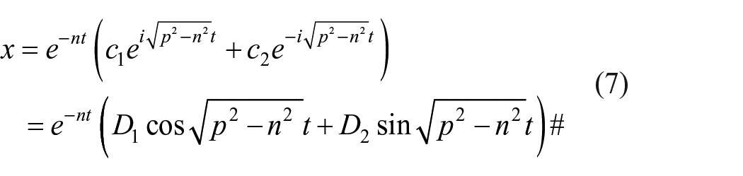

Where A and n are the pending constants, determined by the initial condition. Let t = 0, x = 0,
Bring x into the equation

The resulting impact force change, affected by impact load m, rope modulus k, rope damping c, and initial velocity
Mechanical response during the first impact
During a fall, the rope will bounce back and produce multiple impacts due to its elasticity. Among these impacts, the first impact is the most severe. Figure 5(a) is the curve of the impact force and time during a complete drop. It can be seen from the figure that during a drop, there will be at least 4 obvious impacts. The strength and elongation of these four impacts gradually weakened with the increase in impact times.

Impact force response of kernmantle rope.
Putt the relationship between the fourth impact force and displacement in a graph, as shown in Figure 5(b), it can be seen that the new rope is impacted, and the rope gradually elongates and reaches the maximum elongation value. During the second impact, due to the dissipation of energy, the rebound height of the drop mass is lower than the initial release height, and the maximum impact force and deformation of the rope are smaller, so the curve of the second impact is inside of the first impact curve. As the impact continues, the maximum impact force and elongation of the third impact are smaller than those of the second impact, so the curve of the third impact is inside the curve of the second impact, and the impact amplitude gradually decreases. And so on, the area of the impact area is gradually reduced.
To the specific data, Figure 5(c) shows the maximum impact force among the four impacts, and Figure 5(d) shows the reduced rate of the maximum impact force. It is obvious from the figure that the first impact force is the largest, which is twice the maximum impact force of the second impact. The maximum impact force of the third impact is half the maximum impact force of the second impact. The maximum impact force of the fourth impact is about 40 % of the maximum impact force of the third impact. It can be concluded that in the first three impacts, each impact reduces the maximum impact force by half. After three impacts, the maximum impact was reduced to about one-eighth of the first maximum impact. When the rope is used as a fall arrest safety rope, once the rope can safely withstand the first impact, then all the impact would be safe, because the subsequent impact will become weaker and weaker. In rope protection, the fall of the human body is subjected to the impact force generated by the rope. It can be seen that the maximum reduction rate of the adjacent impact force remains at 0.47 during the first three impacts. Therefore, in the process of falling impact, the fiber rope has better unloading impact ability.
In terms of the time interval between each impact, as shown in Figure 6(e–f), the duration of each impact force process on the rope during the impact process gradually increases as the number of impacts increases. In the process of falling impact, the greater the impact force, the shorter the time, and the quicker the rope response. During the first impact, the rope received a maximum impact force of 10,877.76 N, and the rope had a response time of 0.31 s. When the third impact and the fourth impact were the maximum impact force of 3034.8 and 1842.95 N respectively, the two response times were 0.41 and 0.43 s, and the rope was impacted with a difference of 1191.85 N, but the time difference is only 0.02 s. The response of the rope to the small impact force is gradually insensitive. It can be inferred that the damping effect of the rope itself increases gradually under the small impact.

Comparisons of rope impact modulus.
Impact modulus change
During the impact process of the rope, due to the impact force of the rope, certain structural adjustments will occur, which will lead to changes in the performance of the rope itself. The most important change is the impact modulus of the rope, as shown in Figure 6 shown.
When the rope is subjected to the impact force for the first time, the maximum impact modulus of the rope is 18.1 N/mm when the rope is stretched. As shown in Figure 6(a), the maximum impact modulus of the rope rebound becomes 46.89 N/mm, as shown in Figure 6(b). The elastic modulus of the rope is greater than the impact tensile modulus of the rope, that is to say, the deformation rate of the rope due to external force is higher than the deformation rate of the unloaded rope. During the second impact, the rope was stretched the rope modulus decreased to 14.27 N/mm, and the second rebound modulus decreased to 24.25 N/mm, as shown in Figure 6(c) and (d), the impact and rebound are reduced compared to the first impact. In the third impact, the rope impact and rebound modulus were 9.92 and 12.73 N/mm, respectively, as shown in Figure 6(e) and (f). It can be seen that the impact modulus is related to the impact force during the impact process. The greater the impact force, the greater the impact modulus exhibited. Conversely, the smaller the impact force, the smaller the impact modulus. At the same time, during the impact process, the modulus of the impact process is smaller than that of the rebound process, which reflects the hysteresis of the performance of the rope.
Evolution of continuous impact resistance
The use of the rope is continuous, and it will inevitably be impacted many times during the process. At the same time, there are differences in impact response between new and used ropes. Therefore, the systematic study of the mechanical responses and the changes in the rope performance during the repeated fall of the rope have positive significance for guiding the use of the rope and preventing the occurrence of falling events. This section focuses on the process of new rope continuous drops until it breaks in the end. The evolution of the rope impact performance is discussed through the changes in rope impact force and rope modulus.
Impact response of rope during continuous drops
Drop mass will experience several impact processes from release to final stop, and energy is continuously consumed during the impact process. In the process of each drop, the total dissipated energy is the same, but due to the different performance of the rope, the impact times, impact force, rebound height, etc. of each fall will be different.
Figure 7(a) shows the relationship between the number of impacts and the number of drop times. It can be seen from the figure that the number of impacts is not constant, but changes with the increase in drop times. For a new rope, the number of impacts is 3. This is mainly because the new rope structure is relatively loose. When subjected to impact force, the adjustment of the structure is relatively large, and the energy absorbed is more. On the second drop, the number of impacts is 4. As drop time increases, the rope structure is adjusted, the entire structure becomes tighter, there is relatively less room for adjustment, and relatively less energy is absorbed. From the third drop, the number of impacts is maintained at 5, that is to say, the drop mass can reach a static state after five repeated impacts. When the rope is used as fall protection for the human body, this repeated impact is bound to cause discomfort to the human body.

Evolution of rope impact response with the number of drops.
In terms of impact force, Figure 7(b) shows the changes in the maximum impact force in each drop during the continuous drop. It can be seen from the figure that the impact force during the first drop is the smallest, including the first maximum impact force and the maximum impact force during each subsequent impact. With the increase of drop times, the corresponding maximum impact force is constantly increasing. Among them, the increase in the first impact is the most obvious. All maximum impact forces gradually increase and level off.
From the specific evolution process, the comparison between the first impact force and the second impact force of each fall is shown in Figure 7(d). Both the first impact force and the second impact force gradually increased and became stable. In particular, in the seventh fall before the fracture, the first impact force and the second impact force both showed a downward trend. This decline that the rope is about to break can be used as a signal that the rope is failing. Figure 7(e) shows the first-impact and second-impact reductions for each drop. It can be seen from the figure that the impact force dropped the most during the first impact, which reached a drop of 4.7%, nearly half. With the increase in the number of landings, the decline gradually decreased. The first three falls were steady. After the fourth fall, the drop decreased somewhat. By the sixth fall, the drop was reduced to about 40 %. It can be seen that no matter what the state of the rope is, in the process of each rope fall, the impact force of the second impact is 40%–50% lower than that of the first impact. Figure 7(g) and (i) also confirms this conclusion.
In terms of impact elongation, Figure 7(c) shows the relationship between the maximum elongation of the rope and the number of falls during the continuous fall. The first impact is the largest elongation of each fall, so the first impact elongation of all falls is at the top. Judging from the first impact elongation, the first impact elongation is relatively small. With the increase of the drop times, the maximum elongation increased gradually, and the increase of the second and third falls was larger. After the fourth time, the increased range is stable, and the whole curve shows a linear increasing trend. During a complete drop, the displacement of the second and third impacts is smaller than that of the first impact. Therefore, with the increase in drop times, the maximum displacement of the second, third, and fourth impacts is the same as that of the first impact. That means the subsequent impact does not produce new plastic deformation, and the rope structure gradually tends to be stable.
Impact modulus change
Continuous drops cause changes in the structure of the rope, thereby changing the mechanical response of the rope to impact. In addition to the intuitive performance of impact force and elongation, this response is essentially a change in the modulus of the rope. Figure 8 shows the changes of the impact modulus and rebound modulus of the rope during each impact.

Changes in the impact modulus and rebound modulus.
Figure 8(a) shows the closed loop formed by the impact curve and the rebound curve during a complete impact. The impact modulus and rebound modulus can be obtained by calculating the tangent to the impact curve and the rebound curve. However, the curve is irregular, draw the tangent as shown in Figure 8(b) and calculate the corresponding impact modulus and rebound modulus. As can be seen from the figure, when the first fall, the impact modulus of the first impact is 18.1 N/mm, and the rebound modulus is 54.1 N/mm. The modulus of rebound is three times the modulus of impact. With the increase of t drop times, the modulus of rebound does not change much, basically in the range of 50–60 N/mm. The impact modulus increases with the number of drops. During the first four drops, the impact modulus increased from 18.1 to 45.3 N/mm, an increase of nearly three times, almost reaching the level of the modulus of resilience. During the next few drops, the impact modulus increased slightly and slowly approached the rebound modulus. This shows that during the continuous drops, the rope continuously adjusts its structure under the action of the impact force, the fiber orientation increases, the internal voids decrease, the structure becomes denser, and the entire rope hardens obviously.
Conclusion
In this paper, a device for rope continuous drop is developed, which can realize the simultaneous measurement of rope falling height and impact force, and is used for the research of impact resistance performance of nylon kernmantle ropes. From the research results, the following conclusions can be drawn.
The nylon kernmantle rope will be subjected to several impact processes during a single drop. The maximum impact force is received during the first impact process, and the maximum impact force gradually decreases with the increase of the impact times, and the reduction range is 40 %-50%. The duration of each impact increases gradually with the increase of the impact time.
During a single drop, the first impact produces the maximum impact force and the maximum impact elongation, which produces the maximum elongation-rebound curve, and the rope elongation-rebound curves of the left impact are inside the first elongation-rebound curve.
During the continuous drop of the nylon kernmantle rope, the maximum impact force increases with the drop times. Once the maximum impact force is reduced, this would be treated as a harbinger of rope failure.
During the continuous drop of the rope, the impact modulus and the rebound modulus of the rope gradually decrease with the increase of drop times, and finally tends to be the same, which shows that the whole rope continues to harden.
This research can provide relevant theoretical and data support for the use of ropes, making the use of nylon kernmantle ropes safer, and at the same time providing a reference for the structural design of impact-resistant ropes.
Footnotes
Declaration of conflicting interests
The author(s) declared no potential conflicts of interest with respect to the research, authorship, and/or publication of this article.
Funding
This work was funded by the Humanities and Social Sciences Research Project of Colleges and Universities of Hebei Province [SZ201079]