
Abstract
Thermal comfort property is closely related to the concept of thermal insulation and includes protection against heat. This research paper presents an experimental study on thermal insulation properties, for natural fiber composite materials: a natural fiber (Coir/Jute) with different blend proportions of raw materials mixed with rigid polyurethane foam as a binder. The natural fiber composite materials were characterized by both thermal resistance (Thermal Insulation Value TIV) and also in terms of heat transfer (thermal conductivity). Thermal insulation values were measured according to Lee’s disk method (ASTM C177). The influence of the structure of these materials on the thermal insulating properties was analyzed. The experimental results show the thermal resistance performances of natural fiber composites based on coir/jute fiber materials, thus promoting environmentally friendly solutions.
Introduction
Natural fibers coir and jute are one of the most significant environmental tasks that face the world, to reduce environmental loading and promote the most effective use of resources, 1 Thermal insulation plays an important role in contributing to the automotive heat gains and losses through the envelope. And a study reported active heat insulation of the automotive interior parts. Natural fibers can be transformed into short fibers by the application of mechanical processes coir and jute fibers are widely used in reinforcing epoxy composites. Their availability, good physical and thermal characteristics, processability, minimum cost, & density as well as biodegradability enable them to make good-looking choices. However, their physical properties differ because of their natural origin. 2 The use of coir and jute composites has many advantages compared to biological thermal insulators, including low product cost, good handling, and environmental protection. 3
The industrial materials are manufactured from natural fibers to offer thermal insulation applications. Different researchers give detailed manufacturing processes for composite materials & insulation ingredients and internal automotive applications. So, it gives intelligence to find out the capability of the substances made from natural coir and jute fibers for thermal resistance. Thermal insulation characteristics of materials were investigated, there are several insulation materials made from natural fiber textiles. With different blending ratios of coir fibers and jute fibers. 4
Zeinab et al. 3 addressed heat passed through various kinds of composite materials that were used as thermal insulation. They studied that thermal physical properties depend on the thickness & density of the insulation of substances produced from coir and also the jute/plastic materials. They generalize that, depending on the value of the thermal conductivity which is 0.033 W/mK of the natural fibers textile substances explored, the chosen composites can be used as a thermal insulation material. 5 Thermal insulation characteristics of natural composites with different samples density, thicknesses, and airflow resistance were investigated. The main targets for selecting the composites are to be lightweight materials and manufacturing the desirable materials for thermal insulation. In these circumstances, thermal insulation of composites with different thicknesses and composites density was explored. More off, the heat insulation of all composite samples was analyzed. 6 Likewise, the increase in the density of composites causes an increase in thermal conductivity. According to the thermal insulation measurements, the results show that the thickness of composites increases when the heat insulation of samples increases. 7 The thermal insulation material is one of the very vital properties of the textile resources for technical textile application. And also, the procedures frequently used to measure the thermal insulation values (TIV) are Lee’s disk method, the constant temperature method, and the cooling method. 8
The thickness swelling, water absorption, and mechanical properties of the hybrid composites slightly increased as the layering pattern of hybrid composites changed. Hybridization of coir fibers composites with jute fibers can improve the dimensional stability, extensibility, and density of pure coir composites. Microstructures of the composites were examined to understand the mechanisms for the fiber-matrix interaction with mechanical properties. 9 Coir fiber is pulled out from the husk of the coconut. It is thicker than other natural fibers. Jute fiber is a biodegradable & eco-friendly material. It has good insulating properties of physical & thermal properties. The novelty and main purpose of the research were to explore the consequence of physical properties of composites on the thermal insulation property of coir and jute fibers blended composites. And compression molding composites were manufactured from coir and jute fibers and tested for thermal insulation performance & heat insulation influencing factors such as thickness, density, air permeability, and thermal conductivity were measured according to the ASTM Standard. The composite samples prepared from the natural coir/jute fibers have parameters like fiber length, uniformity ratio, Micronaire value, and fiber strength which are suitable to fabricate the fiber into composite materials shown in Table 1. 10
Coir and Jute Fiber Properties.

The thermal insulation affecting factors such as thickness, areal density, air permeability, and thermal conductivity were measured according to the ASTM and ISO Standard for automotive industry applications. 11 The natural coir and jute fibers are prepared from composite materials. The natural fibers compression molding composites prepared by using coir/jute fiber have been developed and their characteristics have been critically analyzed for thermal insulation behavior in automotive applications. 12 The novelty of the research, heat insulation characteristics of composites with different densities, thickness, air permeability, and thermal conductivity was investigated. The objective of selecting composites was for their light weight for the production of insulation materials. Likewise, the increase in density of the composites leads to an increase in thermal insulation. 11 The major disadvantage of the biocomposites is their high WA property, which in this study was inhibited by the epoxy resin layer. Herein, the results of various tests disclose a noteworthy improvement in the overall properties of bio-composite, in comparison to the neat biodegradable starch matrix, and the biocomposites derived from a starch-glycerol biodegradable matrix reinforced with jute fibers were fabricated using the wet hand lay-up and compression molding techniques Samples having different weight percentages of jute fiber in the starch matrix were analyzed. 13
Experimental methods
Materials
Extraction of coir fibers
The raw materials used for this study were coir and jute fibers Shown in image 1. These fibers were used for the production of composites. Coir is pulled out from the outer shell of a coconut. Brown coir is collected from fully ripened coconuts. It is thicker and stronger and has greater abrasion resistance than white coir. The coir fiber cellulose (about 44%), lignin (45%), pectin and related compounds (3%), and water (5%), the higher lignin content makes the fiber harder and stiffer. It is typically used in mats, brushes, and sacking for preparing composites.

(a and b) Coir/Jute fibers.
Extraction of jute fiber
Jute fibers are obtained from two species of Corchorus, namely C capsular and Colitorius There are also a number of jute substitutes like Bimli which is from hibiscus cannabinus and China jute which is from abutilon theophrasti. Jute fiber consists of overlapping cells with an average of 0.08 in long by 0.0008 in equal diameter; the equal diameter has a uniform cross-section area with the cell. The color varies from yellow to brown with various degrees of grayness and tends toward brown when exposed to sunlight.
Methods
Compression molding
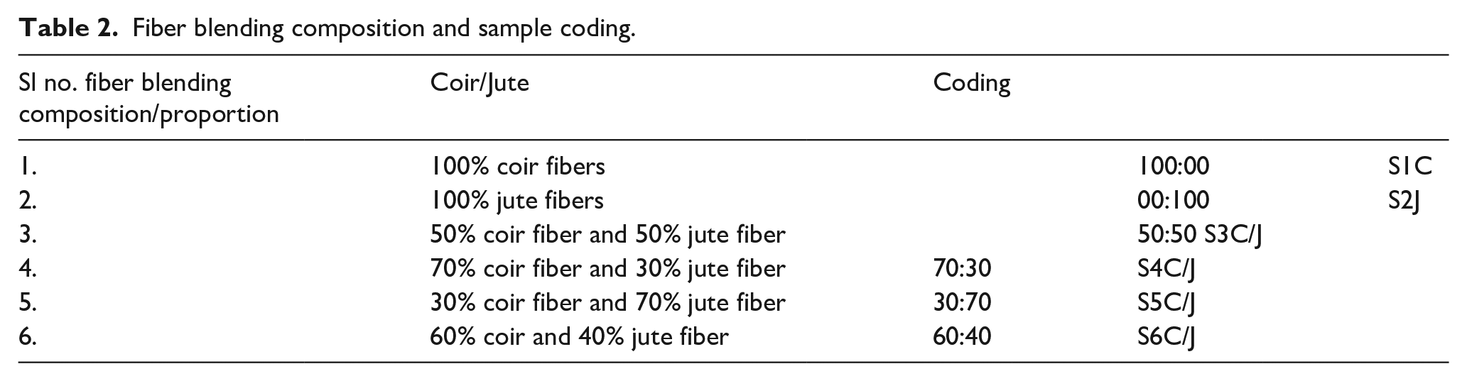
For the production of composite materials from natural fiber coir/jute with thermal insulation properties, a system of bi-component polyurethane foam was used as a binder, for obtaining a material with a rigid structure and closed pores. The polyol component of the foam mixture contains polyol, catalyst, and other additives (BASF, Elastopor H1221/41). The isocyanate component contains a diphenylmethane diisocyanate mixture (PMDI) used by compression molding. The pellets obtained after each mixing process were put in molding frames (10 × 10 × 0.35 cm3) and compression-molded at temperature 185°C for 10 min Shown in image 2, with progressively increasing pressure from 50 to 150 Pa. In this study, 6-panel samples were obtained namely coir and jute fibers were blended with a proportion of (S3C/J 50/50, S4C/J 70/30, S5C/J 30/70, and S6C/J 60/40 respectively by using an electronic balance in grams of fibers. And SC1 100% coir and SJ2 100% jute composites samples were also produced for comparison of their sound and thermal insulation properties, natural materials, and rigid polyurethane foam as a binder in different weight percentages (wt %). The sample blend proportion is shown in Table 2. The thickness was measured parallel along the foam rise direction. Finally, the press was cooled using a cold water flow. From the image 3 shows Six replicate composites were prepared with thickness at 6.5 mm and specific gravity at 1.00 and were obtained for further analyses.
Fiber blending composition and sample coding.

Compression molding methods of composite development: (a) Lower die and (b) Upper die.

Coir/Jute composite samples.
Testing methods
All experimental samples were tested for thermal insulation value, and their thermal & physical properties are determined according to the ASTM standard. Prior to the test, all specimens were conditioned at 65% ± 2% relative humidity (RH) and 25°C ± 2°C Temperatures have been maintained.
Thermal conductivity
The thermal conductivity coefficient of specimens was measured using Lee’s disk method Principle. 14 Determination of thermal conductivity coefficient was performed according to the standard The samples had a size of 15 × 15 × 4 cm, and the temperature range was 0°C–25°C Thermal conductivity of samples was then calculated theoretically by using the Maxwell model as illustrated below where comparisons between theoretical and experimental results, were accomplished. By ASTM D 6343, thermal conductivity was determined.


Where;
Q is the total heat, VI- is the supply energy, a is the cross-sectional area of the material transferring heat, and T- is the temperature on that specific cross-sectional area.
Measurement of air permeability
Flow air permeability is defined as the airflow resistance within a unit of thickness and it reflects the air permeability through porous materials. 14 The air resistance of the materials at a stated pressure differential between two surfaces of the materials is generally expressed in terms of cm3/s/cm2 calculated at operating conditions. To obtain a prescribed air pressure difference between the two materials surfaces, the rate of airflow passing is adjusted perpendicularly through a known area of composites. The air permeability of the composites is determined based on this rate of airflow. The air permeability was determined in accordance with ASTM Test Method D 737.
Measurement of specific porosity
The porosity of a porous material is defined as the ratio of the volume of the voids in the material to its total volume stated by Bhuvaneshwari and Sangeetha. 15 The equation gives the porosity (H).

Where
Va = Volume of the air in the voids,
Vm = Total sample volume of the tested thermal insulation material. Determining the porosity of the nonwoven composite samples based on the ASTM D 3776.
Measurement of thickness
The mean value of all the sample readings of thickness was determined to the nearest 0.01 mm calculated and the result is the average thickness of the sample under test. Determining the thickness of the composite material is done based on the ASTM D5729 standard method.
Measurement of density
The composite specimen with 12 cm diameter and 80 cm2, areas were cut out randomly and weighted. An average of 20 observations was taken for each sample and expressed in kg/m2. The density was computed as shown below.

Where,
W = The weight of sample per unit area, determined by the following standard method ASTM D 3776. Kg/m3 = a mass of material in kilograms in one square area. 4
Measurement of air gap
According to Danihelová et al. 4 flow of air gap is proportional to the material density and fiber size. Fiber packing density decreases the air permeability and air Gap with a resultant increase in pressure drop and hence flow resistance. Based on the airflow test ASTM D-1564, the flow resistance (Rf) of the sample is obtained from the following equation. 16

Where
p = Static pressure differential between both faces of the sample, dyn/Cm2 (10−1 Pa)
v = Air velocity, cm/s
I = Thickness of sample in cm
Measurement of thermal insulation
The thermal conductivity λ of a substance can be defined as a quantity of heat passing through a unit area of the materials per unit time per unit temperature gradient. The guarded hot plate device lambda-Meter EP500 was used for determining the thermal conductivity as per the ASTM-C303 standard. It measures the sample thickness t [m] of the produced composite samples, the temperature difference T [K] over the samples, and the heat flux Q [W/m2]. The thermal conductivity λ [W/(m.K)] is determined based on the defined measurement area S [m2] and the one-dimensional thermal conduction as follows in the equation below 17 λ = the sample size used for measurement was 200 × 200 mm. In this article, the measuring temperatures were 15°C, 30°C, and 45°C. Moreover, the temperature difference between the hot plate and the cold plate was set at 15°C in all sample measurements. The thermal insulation is expressed by the following relationship. 15

Where t [m] = thickness of a sample, λ = thermal conductivity [W/(m.K)].
Measurement of scanning electron microscope
Morphological analysis was performed as per the ASTM D 256 Standard using a JEOL SEM instrument, on cryogenically fractured surfaces of composite samples. The developed natural fiber composites fractured surfaces after tensile testing are examined using a scanning electron microscope (SEM) JEOL JSM-6480LV shown in SEM Images 4(a) and (b).

Thermal conductivity tester.
Results and discussion
Analysis of thermal insulation property
Insulation is one of the most effective methods intended for reducing energy consumption in both the heating and cooling of buildings. Selecting the right materials and determining the optimum insulation thickness in building insulation application is an important issue. 18 Figure 1 shows the thermal conductivity of the following thermal insulation materials, it can be seen that the composite sample’s thermal conductivity is lower when compared to the existing materials on the market (polystyrene and mineral wool), which means they have the best thermal insulation properties. It can be seen that the result for the two materials with 90% rigid polyurethane foam of sample is S5C/J (0.156 W/mK) and S6C/J (0.146 W/mK), and there is an improvement in thermal conductivity when compared to the rigid polyurethane foam, which is one of the most efficient thermal insulators. Better thermal insulation values are obtained when the mineral wool (0.034 W/mK) is compared with the polystyrene (0.04 W/mK). Table 3 showed the thermal insulation properties of coir/jute fiber hybrid composite materials. Figure 1 revealed that it is important to highlight also that the innovative materials made for this study show higher thermal conductivity when compared to other innovative materials based on natural fiber composites according to literature findings. 17 Also, it can be seen in the above figure that the influence on thermal conductivity of the material used for preparing the composites. Thus, the natural fiber coir/jute mixed with polyurethane matrix influences the thermal insulation properties, while natural coir/jute fibers show a slight decrease in thermal insulation when compared to the 100% rigid polyurethane foam.
Physical and thermal insulation properties of coir/jute composites.


Thermal insulation analysis of composite materials.
Analysis of surface morphology
The SEM image shows the composite samples from which the perimeters are measured with scales plan wheel XLU. The natural coir/jute fibers composite samples are measured three times and final average values were taken as a fiber perimeter. The surface area of the fibers was calculated by multiplying the perimeter and the total fiber length in the samples. The surface area of the composite is 25 × 4. The fracture surfaces study of natural fiber composites after the tensile test is shown in SEM Images 5(a) and (b), it is clear that the fibers are detached from the resin surface due to poor interfacial bonding. Pulled-out fibers are clearly visible for composites with 5 wt % fiber content and 3 mm length. However, the composite with 15 wt % fiber and 12 mm length shows good matrix/fiber adhesion. Only very small fiber pull-out coated with matrix materials. The same results were obtained by Sakthivel et al. 2 and Akarsh et al. 19

(a) SEM images/Coir fibers composites and (b) SEM/Jute fibers composites.
Influence of air permeability
Fibers interlocking in composites are the frictional elements that provide resistance to thermal insulation. For a natural coir/jute fibrous material with a given porosity, this means that the flow resistance per unit thickness is inversely proportional to the square of the fiber diameter stated by Sakthivel and Ramachandran. 10 From Figure 2 obtained, the S6C/J sample has high air permeability resistivity with the value of (0.39 CC/S/cm2) which manipulates the high enhancement in air permeability resistance. The other samples like S4C/J and S3C/J also have moderate air permeability resistivity with the value of 0.35 and 0.34 CC/S/cm2 respectively. The random fiber composite material shows superior properties for thermal insulation, which is due to reduced heat transfer and high coupling factor. Additionally, fiber composites with random element distribution yield increased spurious mode suppression due to the random spacing of composite materials. The figure also shows that jute has less air permeability than coir composite materials. It is clear that where the composite density increased, the airflow resistance decreased due to increased resistance to airflow caused by the consolidation of the bonding materials, but also increased the short fiber content which will occupy the air voids. The above said results are in line with the findings of Sakthivel et al.20,21

Air permeability on composite materials.
Influence of specific porosity
Ramlee et al. 18 stated that, in designing a coir/jute fiber, composites have a high thermal insulation value, and porosity should increase along the propagation of the temperature. Thus, from Figure 3 the sample of (S4C/J) has specific porosity of 1.93% and a thermal insulation value of 0.07056%. This shows that the increase in specific porosity materials increases the heat resistance. The samples like S6C/J, S2J, and S5C/J also have specific porosity equal to that of S4C/J. Thus, the specific porosity is increased from S1C to S3C/J which is appropriate for the fiber in between them. The results exposed that when comparing the porosity and micropores the micro pores satisfy the diffusion heat transfer. The TIV of the porous materials was highly dependent on the permeability of the materials. Less porosity and less air permeability of the samples permit the heat resistance a lesser amount at low-frequency levels, but at a higher temperature, the heat resistance the fine pores and experiences friction between the fibers and adhesiveness, thus performing with higher absorption of thermal insulation. The same finding was obtained by Küçük et al. 22

Porosity on composite materials.
Influence of thickness
Several researchers with the intention of heat absorption in absorbent materials have concluded that small heat temperature reduction has a direct connection with thickness. The thumb rule that has been followed is the efficient thermal conduction of absorbent materials is achieved while the material thickness is in relation to one-tenth of the temperature of the occurrence heat the highest point reduction occurs at a conducting the heat temperature of one-quarter ranges of the occurrence heat. This study is clear that heat conduction only at low temperatures, as the material gets thicker. However, at upper temperatures’ thickness has an irrelevant effect on heat conduction. Figure 4 reveals that thicker the material has superior thermal insulation values. The sample S6C/J has the highest thickness of 12.10 mm with a thermal insulation value of 0.06488% Figure 4 clearly shows as the thickness of the sample increases the thermal insulation value of the sample. It found that increasing thickness obviously improved the thermal insulation efficiency of the composite samples at medium and low temperatures. The same finding was observed by Shoshani and Yakubov 23 and Qui and Enhui. 24

Thickness on composite materials.
Influence of density
The density of a material is often considered to be the important factor that governs the thermal insulation of the material. At the same time, the cost of insulation material is directly related to its density. This research also shows the increase of thermal insulation value in the middle and higher temperature as the density of the sample increased. The number of fibers increases per unit area when the apparent density is large. Figure 5 shows that the density increases as the thermal insulation value of the sample increases. The sample S6C/J with a density of 146.7 g/cm3 has the highest TIV of 0.06488%. This is due to the higher fiber content and molecular fraction inside the sample. The other samples like S1C, S1J, and S3C/J also have equivalent density and thermal insulation. Moreover, they showed the following effect of density on thermal insulation behavior of composite materials, less dense and more open structure absorbs the heat of low temperature (50°C). Denser structure performs better for temperatures above (350°C). The above said results are in line with the bindings of Abedom et al. 25 & Sakthivel et al. 26

Density on composite materials.
Influence of air gap
Thermal insulation measurement calculations were performed with and without an air gap of 0.4 and 0.6 mm between the rear of the sample and the backing of the movable plunger of the lea disk tester. The result states that, for the same amount of material, it is much better to have an air gap behind the layer, which coincides with the results. The creation air gap increases thermal insulation values in mid and higher temperatures, in spite of showing minima at certain temperatures. Moreover, the maxima peak for different air gaps is different (higher the air gap distance, the maxima peak shifts toward lower temperatures). This indicates that there is an optimum value for an air gap beyond which there is not much influence seen in thermal insulation properties. For a fibrous material with a given air gap means that the flow resistance per unit thickness is inversely proportional to the square of the fiber diameter. The same statement was observed by Sakthivel et al.27,28
Thermal conductivity on thermal insulation
As the thickness of the developed composite materials increases, the thermal conductivity decreases, which results in a higher thermal insulation value as shown in Figure 6, From the figure, it is clearly noticed that the developed composite samples were analyzed based on their thermal conductivity related to the thermal insulation property. Low values of heat conductivity of developed samples indicated higher thermal insulation. This was necessary to conduct the hotness through the materials. With the increases in temperature, the thermal conductivity shows an increasing trend for samples that have a lower thickness, and the thermal conductivity shows a decreasing trend for samples that have a higher thickness value of composites that were produced from coir and jute fiber, which was providing the best thermal insulation properties. From Figure 6, it is clearly explained, that the thermal conductivity of coir and jute blended sample S5C/J which was developed from 30% coir and 70% jute fibers has a value of 0.156 W/mK which has a thermal insulation value of 0.08725 m2.k/W was higher than the other samples. It is known that lower thermal conductivity leads to better thermal insulation application. Similar findings were obtained by Sakthivel et al.29,30

Thermal conductivity on thermal insulation.
Conclusion
The coir/jute composite material of natural textile fiber to polyurethane foam does not induce a significant change in the thermal conductivity of the composites. Although the differences are not significant, the lowest thermal conductivity value was observed for the composite containing 10% coir/jute samples. As an additional benefit, by increasing the content of the natural material in the composite, the amount of polyurethane foam used is reduced, thus lessening the environmental impact and reducing the cost of the developed material. The results showed that the porous natural coir/jute composites possess excellent performance in thermal insulation of high-temperature heat waves, especially above 350°C. The thermal insulation efficiency of the composite samples at medium and low temperatures can be enhanced evidently by increasing the thickness. The surface morphology of the composite materials was calculated by multiplying the perimeter and the total fiber length in the samples. The fracture surfaces study of natural composites after the tensile test is shown in Images (a) and (b) It is clear that the fibers are detached from the resin surface due to poor interfacial bonding. Pulled-out fibers are clearly visible for composites with 5 wt % fiber content and 3 mm length. However, the composite with 15 wt % fiber and 12 mm length shows good matrix/fiber adhesion. The thermal insulation properties of these natural coir/jute composite materials are useful for the proper application in products such as interior linings materials for auditoriums, halls, apartments, automotive, aircraft, and ducts and enclosures for thermal equipment and insulation for machines.
Footnotes
Author’s Note
G Mohankumar is now affiliated to Department of Mechanical Engineering, Nehru Institute of Engineering and Technology, Coimbatore, Tamilnadu, India.
Declaration of Conflicting Interests
The author(s) declared no potential conflicts of interest with respect to the research, authorship, and/or publication of this article.
Funding
The author(s) received no financial support for the research, authorship, and/or publication of this article.