
Abstract
The technology of warp knitting is one of the more recently developed processes in knitting technology. Complex machine technology and highly productive machines characterize the process. This principle allows obtaining fabrics with various characteristics and for various applications. It is possible to insert straight weft yarns in the textile structure. The weft yarn can be inserted either over the entire width of the textile surface, that is, full wefts, or only over a specific area of the textile, that is, partial wefts. However, weft insertion is the limiting factor in respect of process speed, even if different methods for traversing yarn positioning in the textile industry with the potential to increase the weft insertion speed had been introduced. This paper aims to analyze the inlay yarn condition in respect of yarn tension and yarn speed during the cyclical process of the state-of-the-magazine inlay yarn insertion system and, based on these findings to propose a solution to increase the laying velocity by developing a new method. The approach used is to reduce the vibration induced by the reciprocating movement of the guide bar during inlay operation by using a continuous movement of the mobile elements. This will allow in the future increasing the production velocity, to reduce the stress on the inlay yarn due to acceleration and deceleration.
Introduction
The technology of warp knitting is one of the more recently developed processes in knitting technology. Complex machine technology and highly productive machines characterize the process. This principle allows obtaining fabrics with various characteristics and for various applications. On one hand, further developments during the last decades have greatly advanced fields of application such as the production of spacer fabrics for use in automobile seats, sports applications, or other uses of mattress fabrics. On the other hand, because it is possible to insert straight yarns in the textile structure, this process can be used: (i) to manufacture textile fabrics presenting very low or no elongation, that is, lower than woven fabric, very useful in composite reinforcements for structural mechanical parts, (ii) for inserting yarns which don’t support curvature because they are very delicate, as carbon or optical fibers, or rigid, like metallic yarns, or (iii) for inserting elastic yarns (like in compression orthesis). In these cases, the inserted yarn improves the mechanical/physical properties of the fabric. The most common is to insert inlay yarn in the cross direction.1,2 The weft yarn can be inserted either over the entire width of the textile surface, that is, full wefts, or only over a specific area of the textile, that is, partial wefts.
Moreover, in addition to woven fabric, this kind of process can have high a velocity of production by using warp knitting machines. In fact, Warp knitting has maintained its competitiveness in the past through innovations and rationalization.3,4 It continues to be open to innovations and further developments, which is also shown by the number of patents in this field.5–9 The stitch forming process can achieve speeds of up to 4300 rpm (tricot machine) or 2400 rpm (Raschel machine) against 1000 rpm for a weaving machine. However, at present, the limiting factor in respect of process speed is usually the insertion from the weft inlay yarn over the width of the warp knitting machine. This is reducing the possible machine speed drastically to a maximum of 1500 rpm. Yarn guide bars are moved back and forth in the machine over the required working width, accelerating, and braking at high speed.
Inlay yarn is achieved by an only underlapping guide bar. The yarn is only held in the technical back if a guide bar in front of is overlapping. The inlay yarn is on top of the overlaps during knitting. As the guides of the knitting bar swing through the needles for the next overlap, their underlaps will be laid on top of the inlay yarn locking it in the back of the fabric. 10 In the end, the inlay yarn is maintaining the knitted structure between the overlaps and the underlaps of the ground yarn stitches.
The warp knitting process is a cyclical process that is described by the movements of the involved knitting components. As already described the inlay yarn can only be placed inside the knitting area during 13% of the knitting cycle resulting in approximately 47° of revolution of the main drive shaft from the machine. Therefore, the constant moving rotors need to adapt to that scenario, and a yarn fixing or holding device will be necessary on both sides of the knitting area to cope with the non-cyclical process of inserting the inlay yarn into the machine cycle.
In another way, in the textile industry, different methods for yarn delivery in a traversing positioning way are existing and can be presented. The different technological solutions are presented below in their timeline of development:
The gripper system 11 : A constant back and forth moving gripper with a yarn fixing (holding) device does the weft insertion. The stretched-out yarn segment is pushed into the knitting zone in time to be locked in. The yarn feeding is done directly from an individual yarn cone.
The rotating yarn guide bar 11 : A rotating yarn guide rod is positioning the inlay yarn directly into the hooks from a moving transportation chain. This chain leads the threats in time to the knitting zone to be locked in.
A system of moving (rotating) yarn cones 11 : The weft thread is withdrawn from several simultaneously, but phase-shifted moving, yarn cones. The cones move at a constant distance in an ellipse shape around the yarn transporting chain. Due to the matching speed from the yarn cones, the continuously moving transport chain and the speed of the warp knitting machine the out-stretched and parallel weft insertion yarn reaches the knitting elements in time.
Weft insertion warp knitting system (WIWK): Basis is the simultaneous withdrawal of several inlay yarns from bobbins placed on a fixed creel, called the weft insertion magazine. 1 The yarns are fed into a back-and-forth traversing yarn placing carriage at the back of the machine. This carriage inserts a group of up to 30 weft yarns simultaneously into the hooks from a constantly moving transportation chain. This chain brings the stretched-out inlay yarns continuously toward the knitting elements. The placing carriage is moving in the direction from the machine axis during the insertion of the weft yarn and transversally to compensate for the offset from the transportation chain. This offset of the transportation chain and the continuous withdrawal of the yarn from the yarn cones results in cut waste from the weft insertion yarn. This cut waste is getting bigger the more yarns are prepared simultaneously.
Stringbar technology 12 : It is developed for the simultaneous use of many different pattern yarns. The pattern guide bars are replaced by wires. The yarn guides are attached to these tensioned wires at the required points. The drive and thus the positioning of the wires (strings) is done by laterally arranged stepper motors with a counteracting spring component.
Two belts are driven in opposite directions 13 : Two belts equipped with transportation hooks are used to grab the inlay yarn from a fixed bobbin and insert it in the transportation means from a chain. These belts are driven by two independent motors.
Inlay yarn insertion by rotating wings 14 : The yarn is traversed over the inlay area means of synchronized contrary rotating rotors with blades. The rotating rotors are placed in two closely adjacent planes of rotation and are mounted in offset axes so that the arms sweep across the guide bar in opposite directions to define the traverse stroke.
Rotating eyelet 15 : The yarn is moved along a circular path by a yarn eyelet attached to the inner ring of a torque motor. The yarn path is then transferred via a guide into a traversing movement. With this type of feed, the inlay yarn is only deflected at the respective edges of the knitted fabric. This traversing movement then guides the yarn into the stitch-forming area.
Grooved drum 16 : Machines with grooved drums are widely common for the rewinding of yarns to apply wax or paraffin. The grooved roller is generally directly driven. The yarn is moved alternatingly by the grooves on the circumference of the driven drum.
All these methods have the potential to increase the weft insertion speed due to a higher and constant feeding rate, reduced friction angles along the yarn path from the yarn cone to the knitting zone, and reduced vibrations from the inlay yarn.
The present paper aims to present possibilities to increase the velocity from the process of warp knitting with inlay yarn and to present ways how to reduce the vibration due to the reciprocating movement during yarn inlay. The goal is to increase the production velocity, to reduce the stress on the inlay yarn due to acceleration and deceleration. For this purpose, it has been chosen to have continuously moving transportation and placing elements and a continuous inlay yarn with no cutting waste and intermediate yarn storage. Also, to consider individual yarns and no groups to have a flexible system in respect of yarns used and fabric width. The further target is to have a simple and flexible positioning system inside the warp knitting machine.
Preliminary study
This section will describe the first step designing the weft insertion prototype. The requirements in terms of yarn delivery are defined and the principle chosen is argued.
Requirements determination for the yarn delivery
To design a new system of insertion the first step consists in analyzing in detail the existing method and particularly the instantaneous yarn velocity and tension on a whole inlay cycle. Thus, geometrical analysis and measurement have proceeded.
Materials and methods
The case chosen is the WIWK process because it is the best inlay process existing in terms of weft insertion speed and low vibrations. Therefore, the objective is to highlight the advantages of the best system to understand and improve the weaknesses of the existing system with a proper underlapping inlay guide bar. To achieve it the approach is to measure the instantaneous yarn speed and yarn tension from the starting point, close to the bobbin, up to the knitting zone, during the whole knitting cycle.
During the stitch forming process, the size of the stitch is defined by the length of yarn that is incorporated in each individual loop. This is strongly influenced by the yarn tension and the fabric take-up during the stitch forming process. Also affecting is the elastic elongation from the yarn during the stitch forming and, in addition, about 15% of the yarn drawn into a newly-formed loop is robbed from already-formed neighboring loops (robbing back). 1
Altering conditions during the knitting process like temperature, humidity, and machine speed may influence yarn or machine-related parameters and affect friction between yarn and machine pieces, that is, eyelet, and as consequence, yarn tension. This ultimately influences the yarn tension at the knitting point during the stitch formation. This causes variations in the size of the knitted loops.1,10 Variations in loop length of ±10% due to changes in yarn friction may be experienced at given cam settings and input tensions and these variations can be explained by the phenomenon of “robbing-back.” 15 The ratio of “robbing back” yarn to yarn taken from the cones varies depending on the factors described and can reach values up to 68% of the complete loop length. 16
Two different kinds of yarn feeding systems are existing: positive and negative systems. The positive yarn feeding system gives better control of the yarn length delivered, but it is not usable when a variation of yarn consumption like in jacquard patterns or lace, made by a multi-guide bar machine, is needed. With a positive feeding system, a constant and correct length of yarn under low tension is delivered to the knitting point from the yarn cones. These cones are separated from the yarn-consuming needles by yarn feeders which are directly driven and synchronized to the machine drive. The ratio of “robbed back” yarn to yarn taken from the cones is fixed for a particular fabric quality produced. The negative yarn feeding system is allowing the needles to draw loops whose length is influenced by the yarn condition. 10 The stitch-forming needles pull the yarn directly from the yarn supply. The yarn tension and the yarn elongation are resulting from the yarn tensile properties but also the yarn friction against machine parts, the yarn speed, and the fabric take-up.
Because of the back and forth movement of the inlay carriage, the yarn speed of the inlay yarn during the warp knitting process is not constant during the inlay cycle or course. As a consequence, the yarn elongation and the yarn tension are not constant over the stroke from the inlay carriage. Therefore, yarn tension and yarn speed measurements are important to understand the process of inlay yarn processing.
For the present study, a WIWK machine (RS4-MSU-N in 18GG from Karl Mayer, Obertshausen, Germany) has been used. The principle of the machine set-up is illustrated in Figure 1. The creel with the bobbins and the storage feeding systems (MSF3 CAN from Memminger-IRO, Dornstetten, Germany) are placed on the side of the machine. For the measurements, a cotton two plied yarn (2 × 25 tex) has been used. The inlay carriage at the backside of the machine is moving 18 yarn ends simultaneously. One complete cycle (double stroke) from the carriage over the transportation chain area including the cross-movement to place the yarns into the transportation hooks lasts 5.1 s. Therefore, 423 inlay yarn ends are inserted each minute. On this machine for proceeding to measurements, high-frequency yarn tension measurements are carried out at P1 and P4 (Figure 1) with yarn tension sensors (125.12 from Honigmann, Gevelsberg, Germany) with an acquisition frequency respecting the Shannon theorem to have a signal maximum frequency of 1 kHz. The very compact design of the 125.12 Honigmann sensors with short transducers makes it possible to record and display even the very steep and rapid increases in yarn tension. This sensor is fixed to have minimum interaction with the measured as recommended, 17 therefore the wrap angle is quite small, that is, approximately 15°.

Principle of an inlay warp knitting machine with measuring positions. 18
For additional analysis, the yarn tension and the yarn speed are measured simultaneously at the measuring P1 (Figure 1). A TMS multi-sensor (BTSR S.p.a., Varese, Italy) is set up for this measurement. This sensor is detecting and monitors the yarn tension and the yarn speed, with a signal maximum frequency respectively of 200 and 20 Hz. They are equipped with rollers to limit yarn abrasion and to reduce the influence of the measuring system on the textile process itself.
To resume, the yarn tension meters had been placed in positions P1 and P4 (Figure 1). The yarn speed sensor measuring at P1 (Figure 1). To synchronize the yarn speed and yarn tension measurements with the carriage movement a capacitive positioning sensor is installed on P2, measuring instantaneously the position of P4 (Figure 1).
The traversing yarn carriage (Point 4 in Figure 1) is moving along the machine axis to transport the inlay yarn over the fabric and perpendicular to the machine axis to compensate for the movement of the transport chain and to place the inlay yarn inside the hooks from the transportation chain (number 7 in Figure 1).
Figure 2 shows the inlay yarn system of the WIWK machine. The pendulum eyelet on top of the traversing inlay carrier P1 is not in the center of the transportation chain.

WIWK machine with yarn carriage (a) on the left side and (b) on the center. (a) Point 1 is the pendulum eyelet and Point 2 is the point of return on the left side, that is, the side of the creel. (b) Point 3 is the right point of return, and 4 is the yarn carriage.
The distance x1 in Figures 2 and 3 indicates the position relative to the left point of return (POR) P2 from the carriage system and y the height above the chain level. P1 is the position from the last fixed eyelet over the traversing yarn carriage from one side to the other side alternatively, that is, from the two points of return P2 and P3. The geometrical situation from the WIWK process with an inlay yarn carriage is described in Figure 3.
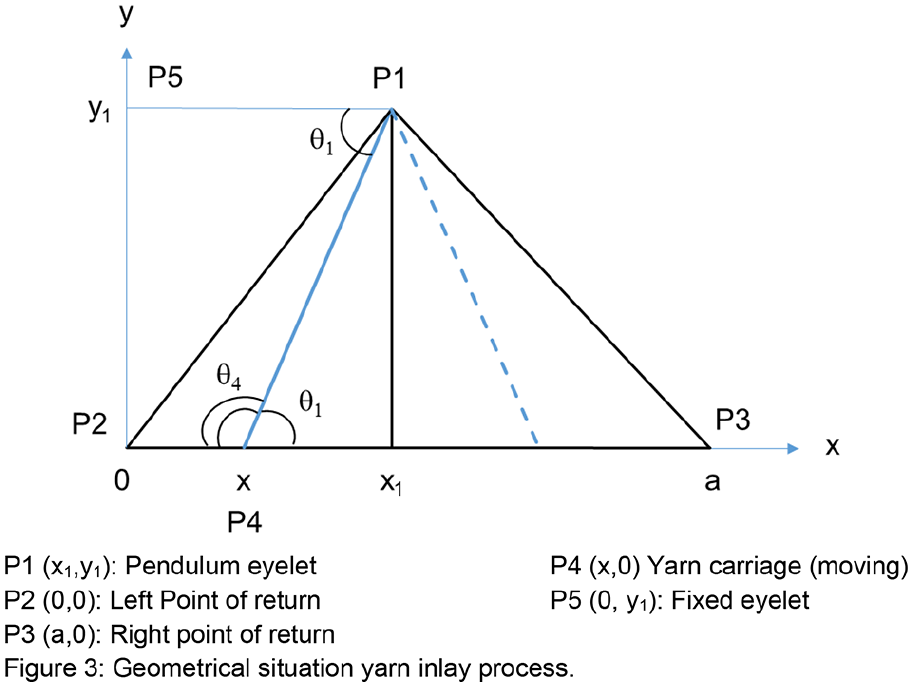
Geometrical situation yarn inlay process.
Results
Based on the machine set-up described in section 2.1.1, the yarn speed is calculated.
The carriage cycle is starting at the left POR P2 (Figure 3) and then it is moving along the machine axis passing under the pendulum eyelet to the right POR P3 (Figure 3) and is there returning to the starting point.
From Figure 3 the following equations expressing the yarn length between the pendulum eyelet and the traversing yarn carriage can be obtained. Based on the geometrical situation, the total theoretical yarn length from P1 to P4 the complete yarn carriage movement cycle can be calculated. The perpendicular movement to compensate for the movement from the chain is not considered.
- With a yarn carriage movement from P2 to P3, that is, left to right, the yarn path is from P2 to P4, then the yarn length L relative to yarn carriage position x is:

- With a yarn carriage movement from P3 to P2, that is, right to left, the yarn path is from P3 and P4, then the yarn length L relative to yarn carriage position x is:

From the results obtained from the positioning sensor on P4 (Figure 4), it can be observed the yarn carriage movement is sinusoidal and can be expressed as:

where
T: the period of a complete yarn carriage cycle back and forth (s),
t: time (s),
a: is the distance between P2 and P3.

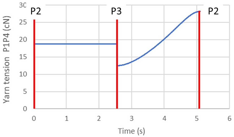
Signal relative to time from yarn tension sensors at P1 (top) and P4 (bottom) and carriage position (top). Points 2 and 3 are indicated to follow the yarn carriage position on the machine.
Therefore, from equations (1)–(3), the yarn carriage position can be expressed relative to time.
Moreover, the yarn speed can be expressed:


In the present machine, x1 = 0.85 m, y1 = 1.33 m, a = 1.7 m, and T = 5.1 s, therefore the yarn speed relative to time is illustrated in Figure 5(a).

(a) Calculated and (b) measured yarn speed at P1 between the POR and the yarn carriage during a whole yarn carriage cycle, that is, from P2 to P3 and P3 to P2.
Figure 5(b) illustrates the yarn speed measured during a whole yarn carriage cycle at P1. The sensor used has a maximum frequency of 20 Hz which represents approximately 100 data points on a whole cycle, that is, 5.1 s, and is therefore sufficiently representative. From equations (4) and (5), it can be observed, that calculated and measured yarn speed with the sensor at P1 are different. However, the experimental evolution shows a delay which can be because in equations (1)–(5), yarn friction in the different eyelets and yarn inertia unwinding are not taken into account. However, from these results, it can be concluded the real evolution of the yarn speed (Figure 5(b)) is not as smooth as the speed evolution of the yarn carriage, that is, with a sinusoidal evolution (Figure 5(a)). The speed change is very impulsive, from the starting point to the endpoint whatever the yarn carriage direction. The maximum speed is during the initial phase of the stroke.
The tension variation during the yarn carriage cycle due to yarn friction between the different eyelets can be evaluated by using the capstan theory (Figure 6):

with
Τ0: yarn tension before the eyelet
Τ1: yarn tension after the eyelet
µ: coefficient of friction between the yarn and the eyelet,
α: wrapping angle.
When considering more than one capstan, the evolution of the tension is:

with
Τ init : starting point yarn tension,
Τfinal: ending point yarn tension,
αi: wrapping angle at the eyelet i.

Capstan description.
From Figure 6 the relation between the wrapping angle and the angle formed by the yarn before and after each eyelet is:

Then for several capstans, that is, eyelets 19 :
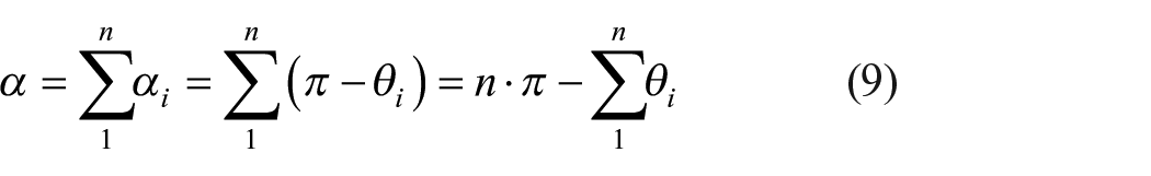
The wrapping angle expression depends on the yarn carriage direction (Figures 3 and 6):


where
θ1: angle
θ4: angle
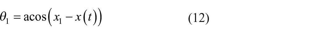
The evolution of θ1 relative to yarn carriage position is:
The tension between P1 and P4 relative to yarn carriage position/time is expressed:

Where
ΤP1: Initial yarn tension at P1.
Figure 7 illustrates the calculated yarn tension during a complete yarn carriage cycle. From the equation (9) and the corresponding findings in equations (10)–(13) it can be observed that the calculated yarn tension and the measured yarn tension (Figure 4) follow a similar basic cycle. However the experimental evolution shows a drop in yarn tension (P2->P3) that is corresponding with the drop in yarn speed visible in Figure 5(b). That would indicate a connection between measured yarn speed and measured yarn tension.
Calculated yarn tension evolution between P2 and P3 due to yarn friction in the eyelets.
Preliminary study conclusions
Some requirements can be extracted from a qualitative point of view from the preliminary study. During the insertion of the weft yarn, the yarn tension and the yarn speed fluctuate greatly. This is causing longitudinal and transversal oscillations in the weft inlay yarn. 20 These oscillations get more intense with increasing machine speed and therefore increasing yarn speed. This mechanism results in limitations in the processing speed for the inlay yarn process and the warp knitting machine. For a further increase in machine speed and to achieve greater process reliability, a more even and constant feeding of the yarn must be achieved. To improve the weft yarn feeding condition during the inlay process in warp knitting machines continuously moving transportation and placing elements are a solution that is, no alternating movement introducing yarn tension variation. An ideal solution would allow to combine the continuous movement of the components with the reciprocating placement of the inlay yarn into the knitting zone of the warp knitting machine. These continuously moving components without cyclical stopping and acceleration will also reduce the power consumption of the warp knitting machine. Further it is better to not have intermediate yarn storage that is reducing the complexity of the inlay warp knitting machine, reduces machine cost and increases the process reliability by lesser components involved in the inlay process.
Choice of yarn delivery technic
In the previous section, the specifications for a new and innovative traversing system for the inlay yarn insertion in warp knitting machines have been identified. Therefore, the proposed solution is to adapt a technology that is used in the bobbin winding process. This paper will be focusing on the technology of rotating blades.
The technology of the rotating blades used in yarn winding machines is performing high-speed reciprocating movements of the yarn, leading the winding yarn without incorporating big friction angles on the winding package. This reduces irregular stresses on the yarn and is increasing the process reliability. The aim of the research is to adapt the advantages of this technology from the winding machine to the warp knitting machine.
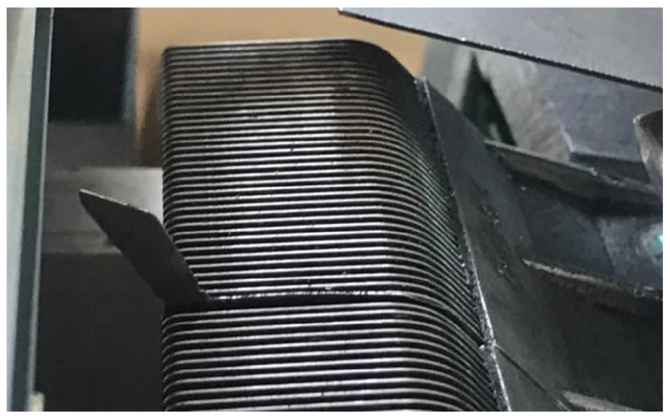
The rotary blade yarn traversing system comprises two rotors with two or three blades each (Figure 8). These blades are turning synchronized in opposite directions. One rotor is traversing the yarn from the left turning point to the right side, performing a hand over to the second blade which is then traversing the yarn back to the right side. At the direction turning point on the right side, the hand over to the blade from the rotor which is turning in the opposite direction is again made. Based on this cycle the yarn can traverse alternating over the inlay area under constant rotation from both rotors involved. The diameter of the rotary blades of approximately 20 cm is resulting in a limited maximum fabric width of 15 cm which cannot be reduced or changed. Therefore only applicable for smaller fabric width.

Pair of rotors with each three blades.
Winding prototype developed
Elements to the design of the prototype
The use of rotary blades for yarn inlay into the warp knitting machine will allow a highly productive and energy-saving process that can be used for newly developed as well as for existing products. The principle of the weft insertion with rotary blades is illustrated in Figure 9.

Two preliminary design studies have been done to evaluate the mechanical parameters and the technical task.
For an initial trial setup, the blades are placed vertically in front of a vertical movable needle bar. The model is manually driven and made from wood. A mechanical model from a cone winding machine is set up. This study showed the technical challenges to integrate the rotary blade unit into the inlay yarn process from warp knitting machines.
In the winding scenario (Figure 10), the yarn path goes straight from the spinning machine through the pair of rotors on the rotating yarn cone. No significant deviation angle from the yarn on the blade edge occurs. During the transversal movement, the yarn is constantly wound up on the cone. During the direction change at the left or the right edge from the winding areas, the following blade in the opposite direction reaches directly into the stretched yarn. The handover from the yarn is made without an increasing deviation angle from the yarn (Point 1 in Figure 10).

Yarn path in a bobbin winding model.
The warp knitting process is cyclical. The cycle of the process is determined by the movement of the involved knitting elements which are directly driven from the main shaft of the machine. The weft insertion is bound into the stitches. At the start of a new loop formation cycle, the weft insertion is guided by the traversing rotor over the insertion area. This creates a changing wrap angle of the yarn on the edge of the blade from the rotor (Figure 11).

Wrapping angle of the yarn on the edge of the blade from the rotor.
The horizontal and vertical drag angles are also taken into account (Figure 12). The inlay yarn is bound in the edge needle of the last course of stitches. The rotating rotor guides the open end of the weft insertion from the edge needle to the opposite edge of the fabric. Consequently, the transported yarn is describing the angle horizontally and vertically between the contact point on the transporting blade edge and the last needle.

Horizontal drag angle rotor position: (a) close to the fabric edge and (b) distant to the fabric edge.
The drag angle besides the horizontal component (Figure 12) also has a vertical component (Figure 13).

Vertical drag angle.
The yarn is transported from the rotating blades across the width of the inlay area. The yarn is pulled from the yarn supplying storage feeder. Due to the changing wrap angle from the yarn on the transporting rotor and the changing yarn tension during the transversal movement the yarn is moving (climbing) along the rotor edge as visible in Figure 14.
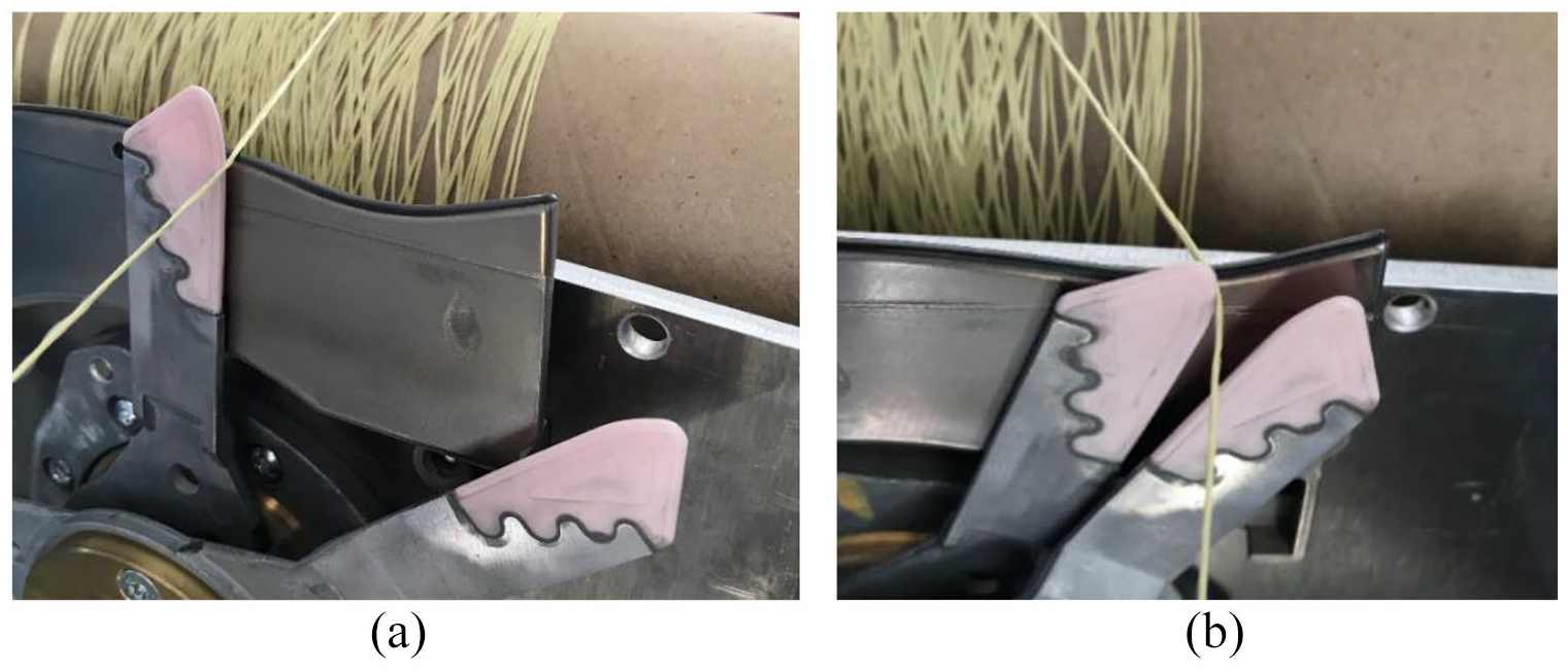
Positioning of the inlay yarn on the rotor: (a) in the middle from the insertion and (b) at an edge from the insertion.
Prototype
The prototype is constituted of two rotors with three blades that are rotating in opposite directions. These two rotors perform the direction change on each side of the warp knitting area. To ensure the proper handover the two centers of rotation show a vertical offset.
For the initial prototype, the following topics are important:
- Controlling the handover from one blade to the opposite rotating blade,
- Maintaining the inlay yarn on the blade during the traverse,
- Reducing stress for the inlay yarn by adjusting the deviation angle on the blade edge.
Therefore, the twin-rotor system used in the Barmag winding rotor blades (Leverkuser Strasse 65 in 42897 Remscheid Deutschland) is selected (Figure 15). The positioning from the rotating centers of the twin-rotor system from both rotors as well as the offset positioning relative to each other is designed to ensure a working handover at the turning points of the traversing zone.

The principal design features from the demonstrator unit are:
- The demonstrator unit is made as a stand-alone solution with a width of 12″ in gauge 18. The device uses latch needles;
- The drive and the relative timing during the knitting cycle from all involved knitting elements is made mechanically over the main drive shaft;
- The warp beam is located on the top;
- The warp beam is non-braked;
- The warp yarn is negative fed;
- The warp yarns are individually guided via spring-loaded yarn tensioners;
- The yarn supply from the inlay yarn is made directly from the cone;
- The trial stitch setup is to knit pillar stitch with inlay yarn.
The blade unit is placed at a relative 72° angle to the knitting needle bar (angle η shown in Figure 16). Therefore, the deviation angle between the needle bar and the rotor plane η can be reduced.

Positioning angle η from the rotary inlay device and inlay yarn guide bar (number 2).
The inlay yarn is placed from the top inside the knitting zone via the guide bar unit (number 2 in Figure 16) which is placed over the rotary blade unit to prevent the yarn during traversing to slip from the blade from the rotor.
Figure 17 shows the set-up from the prototype unit. On the machine frame (3 in Figure 17) the positioning rotary device (4 in Figure 17) is mounted in front of the knitting zone (7 in Figure 17). The warp yarns are drawn from the warp beam (1 in Figure 17), which is mounted on the top of the machine while the inlay yarn is supplied from the front of the machine (2 in Figure 17). The machine drive and the lateral movements are assembled at the side of the machine (6 in Figure 17).

Set up demonstrator unit.
Results and discussion
During initial trials while setting up the demonstrator unit the horizontal and vertical drag angle from the inlay yarn become visible. The drag angle scenario can be minimized by placing the rotor unit at an angle of 72° (angle η in Figure 16) to the needle bar.
When using the rotary blades unit in a warp knitting machine only a single yarn end is used. The speed from the inlay yarn is getting high. In addition to that, it is considered the time frame of only 13% from a center shaft revolution is available for the weft yarn insertion. The remaining 87% of the insertion unit has virtually to stop. This would eliminate the biggest advantage of the system: the high-speed feeding potential from the constantly rotating system.
Based on these results, improvements to the prototype can be focused.
One approach will be the redesign of the weft yarn placing elements. In warp knitting machines one individual mechanical drive component is moving the comb plate and the weft yarn placing element. The development aims to combine these two components into one part with one common drive – or, depending on the design, a split component – and to execute the movement with one drive system.
This redesign as shown in a model in Figure 18 or in Figure 19 as installed part in the demonstrator unit will reduce the number of moving components inside the warp knitting machine as the comb plate and its driving bar are eliminated. This will reduce machine and process costs. A reduction of vibrations in the yarn and safe guidance into the knitting zone increases the process reliability.

Sample design of a combination of sinker unit and a weft yarn inserting element. 23
Sample geometry from a combined part.
Further, they will allow a flexible positioning of the inlay yarn along the machine axis. Such combination elements on a drive unit have not been used in the warp knitting technology yet.
Moreover, to use the potential of the high-speed feeding and traversing system an intermediate transport and storage system for spread yarns is applicable like in the basic prototype shown in Figure 20. From that system, the inlay yarn must be presented to the knitting zone. The high-speed capabilities and the very compact design of the rotor unit will have an impact on the production speed of the warp knitting machine. Advantages compared to the carriage system from a magazine insertion system will be on one hand reduced machine and process cost and, on the other hand, a new product with new features will be possible. These advantages become obvious when working on smaller fabric widths.

Basic prototype placing the rotary blades unit to a transport chain system.
Finally the diameter of the rotor blades is limiting the maximum overall width of the possible inlay area. To achieve a greater inlay width, a possible handover from one pair of rotors to a further pair of rotors needs to be developed. This development will also allow to have variation in the inlay length to a greater length, however the length of the inlay yarn using one pair of blades is fixed. At the end the shortest inlay width is due to the diameter of the rotary blade diameter and the maximum width will be due to the number of rotary blade pairs in alignment.
Conclusion
In this paper, a new design of yarn carrier for weft inlay in warp knitting technology is proposed. Firstly, yarn tension and yarn speed variations during a knitting cycle have been studied. The variations have been explained from an experimental and theoretical approach. Some requirements have been identified for the new system. Then, a rotary blade system is chosen and a prototype is designed by considering the necessary path of the yarn.
To establish a valid new and alternative weft insertion system several main obstacles remain. The major technical challenge will be to cope with the timing from the given machine cycle and to use the available time window to place the inlay yarn into the knitting zone as effectively as possible. Further, the presentation from the inlay yarn into the knitting zone needs to be done in time, by dumping all yarn vibrations and handling the yarn drag angle. This can be achieved using a single part as a combination of the comb plate and the weft yarn placing element and using an intermediate storage unit like a feeding chain.
The potential of increasing the speed of the warp knitting machine, and reducing energy consumption, reducing process costs is highlighted. The reduction of machine cost due to the reduction of moving parts required for the inlay technique can be achieved. The technology with one pair of rotors is especially possible for warp knitting machines with a smaller width for narrow fabrics.
Work for the future: Further research and development are necessary to control the drag angle from the inlay yarn during the inlay process, the relative timing from the inlay process to the knitting process, and a controlled placement from the inlay yarn into the knitting zone. A possible solution can be a rotary eyelet. 24
Footnotes
Declaration of conflicting interests
The author(s) declared no potential conflicts of interest with respect to the research, authorship, and/or publication of this article.
Funding
The author(s) disclosed receipt of the following financial support for the research, authorship, and/or publication of this article: The project “Kettenwirkprozess mit Flügelschusseintrag” (warp knitting process with rotary blades for weft insertion) is funded by the state of North Rhine-Westphalia using resources from the European Regional Development Fund 2014-2020 (ERDF).