
Abstract
In this work, an existing method of capturing Fe-based fine particles by magnetic fiber is improved, and a weaving method for the fiber filter material is further determined. Different combinations of magnetic fields could form around the magnetic fibers, which change the interaction between orthogonal magnetic fibers when a uniform magnetic field is applied along the X-, Y-, and Z-axes. Therefore, the process of particle capture by the orthogonal magnetic fibers under three configurations was compared using the computational fluid dynamics-discrete phase model (CFD-DPM) and a special user-defined function (UDF) of the magnetic force. The results show that the interaction between orthogonal magnetic fibers could either inhibit or promote the capture of Fe-based fine particles by adjacent magnetic fibers. In industrial production, the magnetic filter material is suitable for the weaving method for the alternate use of magnetic and traditional fibers. When a uniform magnetic field is applied along the X-axis, this weaving method makes the capturing performance of orthogonal magnetic fiber best. Moreover, the magnetic characteristics, flow characteristics, and combination sequence of magnetic fields should be considered. This study provides scientific researchers with new insights for the development of novel high-efficiency fibrous filters to reduce particulate pollutants emissions.
Introduction
The particulate pollutants generated by industrial production processes, especially by the iron and steel industries (e.g. sintering, ironmaking, and steelmaking), must be removed from the exhaust before being discharged to prevent the particle release from polluting the environment. The crushing of iron ore raw materials and steam condensation under high-temperature conditions by iron and steel industries emit particles that contain numerous metal components. The prolonged exposure of workers to metal dust and smoke leads to repeated respiratory system stimulation, lung function impairment, and chronic obstructive pulmonary disease (COPD). 1 Even it harms the central nervous systems. 2 From the comprehensive consideration of economy and collection performance, fiber filtration is currently the most common technology for removing particles from flue gas compared with electrostatic, 3 cyclone, 4 and wet dust removal. 5 The fiber filtration efficiency can be improved by changing the fiber cross-sectional shape, 6 fiber diameter, 7 fiber orientation distribution, 8 and fiber arrangement2,9; loading nanofibers on the surface of the fiber layer10,11 or changing the structure of filter media.12–15 However, traditional fibers have a “breakthrough” in the PM2.5 range, 16 especially for particles with a size of 0.5–1.0 μm, which are not easily filtered using conventional filters.2,8 It makes compliance with increasingly stringent environmental regulations for pollutant emissions from flue gas a challenge. Fortunately, in the iron and steel industries, the Fe content of metal particles produced during the technical production process far exceeds that of other elements,17,18 and Fe element exists in the form of Fe2O3 and Fe3O4. 19 These Fe-based particles are easily magnetized in a magnetic field and removed by magnetic forces. The study found that, for fine particles with less than 2.0 μm, the filtration efficiency of magnetic filter material improved by 20% higher than traditional filter material. 20 Compared with the electret fibers produced and put into industrial application, the magnetic fibers are still in the stage of theoretical research. However, magnetic fibers now have a complete production process and will play an essential role in emission control of the iron and steel industries in the future. 20 In addition, high-gradient magnetic separation (HGMS) technology can use the external magnetic field to saturate the magnetic media and enhance the magnetic field strength around it.21,22 Combining the two technologies can help the magnetization of magnetic filters reach the saturation state. However, the fibers in magnetic filters exhibit strong interactions through the magnetic field. When Fe-based particles are captured by magnetic fibers, these are inevitably affected by the magnetic field of adjacent magnetic fibers.
This paper studies the influence of interaction between orthogonal magnetic fibers on the capture of Fe-based fine particles by adjacent fibers. The captured particle trajectories and filtration efficiency of each fiber under the interaction between orthogonal magnetic fibers were calculated and compared with those without interaction to determine the degree of influence. The process of PM2.5 capture by traditional fibers (gas-solid two-phase) was simulated by different methods: computational fluid dynamics–discrete phase model (CFD-DPM) method,2,23 Monte Carlo method, 24 Lattice Boltzmann method (LBM), 9 and computational fluid dynamics–discrete element method (CFD-DEM),13,14 or the use of OpenFOAM to simulate particle capture process. 25 The simulations of the magnetic filtration process considered the fiber interactions when the research object changed from traditional to magnetic fibers. The particle trajectories and filtration efficiency were calculated using the commercially available software ANSYS-Fluent with a discrete phase model (DPM) and a special user-defined function (UDF) of the magnetic force. Because the orthogonal magnetic fibers are perpendicular to each other, the directions of the external magnetic field that enable magnetic fibers to reach the magnetic saturation state include the longitudinal, transversal, and axial directions. 26 Different combinations of magnetic fields formed around the two magnetic fibers when a uniform magnetic field was applied along the X-(Hx), Y-(Hy), and Z-axes(Hz). Therefore, particle capture by orthogonal magnetic fibers in the three configurations was modeled and derived to write different UDF programs. This study aims to reveal the influence of the interaction between orthogonal magnetic fibers and determine the weaving method for magnetic filter media in industrial production. It attempts to provide the theoretical foundations for the development of high-performance fibrous filters.
Multiphase flow model
Flow equation
In the Stokes flow regime, the pressure drop is caused by viscous forces as air flows past the fiber. The flow field through a given domain is determined using the following conservation of mass and momentum equations 11 :
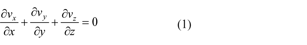


where p is the gas pressure (Pa); µ is the dynamic viscosity of the flow field (Pa s); vx, vy, vz are the component velocities in the x, y, and z directions, respectively (m/s).
Particle motion balance equation
The particle motion governing equation 2 :

where mp is the particle mass (kg); vp is the velocity vector of the particle (m/s); v is the velocity vector of the flow field (m/s); µ is the dynamic viscosity of the flow field (Pa s); dp is the diameter of the particle (m); g is the acceleration of gravity (m/s2); ρp is the density of the particle (kg/m3); ρ is the density of the flow field (kg/m3); and Gi is a random number chosen from a normal distribution with a zero mean and unit variance. Cc, Knp, and S0 are the Cunningham correction factor, particle Knudsen number, and corresponding spectral intensity of the noise, 27 respectively. These are calculated via the following equations:
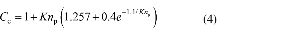


where λ is the mean free path of gas molecules (m); kB = 1.38 × 10⁻²³ J/K is the Boltzmann constant; T is temperature of gas (K).
Fother includes negligible forces (N), for example, the pressure gradient force, Basset force, Magnus force, and Saffman lift force. 28 FM is the magnetic force added in the magnetic field through a UDF (N). The formulas for the radial and tangential magnetic forces are calculated as follows 29 :

where µ0 = 1.256 × 10⁻⁶ N/A2 is the magnetic permeability of vacuum;
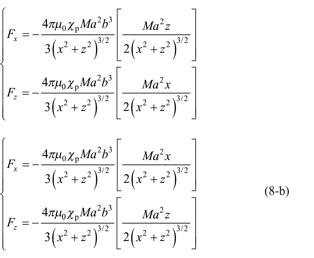
In polar coordinates, the radial force and tangential force acting on Fe-based particles are Fmr and Fmθ, respectively. Moreover, the magnetic field force of the magnetic fiber on the Fe-based fine particles is perpendicular to the magnetic fiber. The magnetic fiber doesn’t exert magnetic field force on the particles along the axial direction. Therefore, the magnetic field force along the axis of the magnetic fiber was not considered in the numerical simulation. Through the transformation of the coordinate system, taking No.1 magnetic fiber as an example in Cartesian coordinates, when a uniform magnetic field was applied along the X-(Hx), Y-(Hy), and Z-axes(Hz), respectively. The corresponding magnetic field force of No.1 magnetic fiber acting on the Fe-based fine particles are as follows:


Physical model
Calculation model and boundary conditions
During simulation, the inlet velocity, air density, particle density, and dynamic viscosity were set at 0.1 m/s, 1.225 kg/m3, 2500 kg/m3, and 1.83245 × 10⁻⁵ Pa s, respectively. Figure 1 presents the calculational model and boundary conditions. The airflow was assumed to enter the filter domain through a velocity-inlet and leave through a pressure-out boundary condition, the surround of the computational domain imposed the symmetry boundary conditions, and the fibrous surface assumed the no-slip boundary conditions.8,23,30 The length (l), height (h), and width (w) were set at 250, 80, and 80 μm, respectively. The diameter of the magnetic fibers was 20 μm, and the distance between the two magnetic fibers was 10 μm. Moreover, “Situation 1” represents the external uniform magnetic field along the X-axis (Hx); “Situation 2” represents the external uniform magnetic field along the Y-axis (Hy); “Situation 3” represents the external uniform magnetic field along the Z-axis (Hz).

Schematic diagram of calculational domain and boundary conditions: (a) Situation 1, (b) Situation 2, and (c) Situation 3.
The Fe-based particles emitted by iron and steel industries characterization test was performed shown in Figure 2. The SEM images revealed that the Fe-based fine particles were approximately spherical particles and uniformly distributed (Figure 2(a)). The Nano Measurer software test results showed that the particle diameter range of Fe-based fine particles was 0.52–6.32 μm, and the average particle diameter was 2.56 μm (Figure 2(b)). In the simulation calculation, the diameter range of the particles was chosen to be 0.5–2.5 μm. Moreover, it can be seen from the hysteresis loop of converter ash and refined ash in iron and steel industries, when the external magnetic field reached 0.5 T, the saturation magnetization of the converter and refined ash were 22.5 and 3.32 emu/g, and the magnetic susceptibility were 0.1363 and 0.01989, respectively (Figure 2(c)). Therefore, the magnetic susceptibility of the Fe-based particles in the magnetic field was 0.025 in a reasonable range.

Characteristic test of dust emission in iron and steel industry: (a) scanning electron microscope (SEM), (b) particle diameter distribution, and (c) vibrating sample magnetometer (VSM).
Magnetic field distribution
The magnetic pole form of magnetized magnetic fiber is shown in Table 1. When the external magnetic field passes through the orthogonal magnetic fibers, the two magnetic fibers are magnetized. In micromagnetism, based on a macrospin model, the electron spins in hundreds of tiny elementary magnets can spontaneously aligned in a small area to form a spontaneous magnetization region, called magnetic domain. When a uniform magnetic field is applied, the internal magnetic domains are aligned neatly and in the same direction. Therefore, the magnetic fibers are magnetized and magnetically enhanced. From a macroscopic perspective, the formation of south and north poles on magnetic fiber was assumed. However, all with their orientation depending not only on the external magnetic field, but also on the superposition with magneto-crystalline and shape anisotropy. To simplify the study, the effects of magnetocrystalline and shape anisotropy are ignored.
Magnetic pole form of magnetized magnetic fiber.

Moreover, the combination of the magnetic fields around two vertical magnetic fibers is presented in Table 2, which was calculated by Comsol software. When the external uniform magnetic field along the X-axis (Hx), the magnetic field generated by No.1 magnetic fiber is perpendicular to No.1 magnetic fiber, and the magnetic field generated by No.2 magnetic fiber is perpendicular to No.2 magnetic fiber. When the external uniform magnetic field along the Y-axis (Hy), the magnetic field generated by No.1 magnetic fiber is parallel to No.1 magnetic fiber, and the magnetic field generated by No.2 magnetic fiber is perpendicular to No.2 magnetic fiber. When the external uniform magnetic field along the Z-axis (Hz), the magnetic field generated by No.1 magnetic fiber is perpendicular to No.1 magnetic fiber, and the magnetic field generated by No.2 magnetic fiber is parallel to No.2 magnetic fiber.
Combination of the magnetic fields around two vertical magnetic fibers.

Model validation
Mesh independence verification
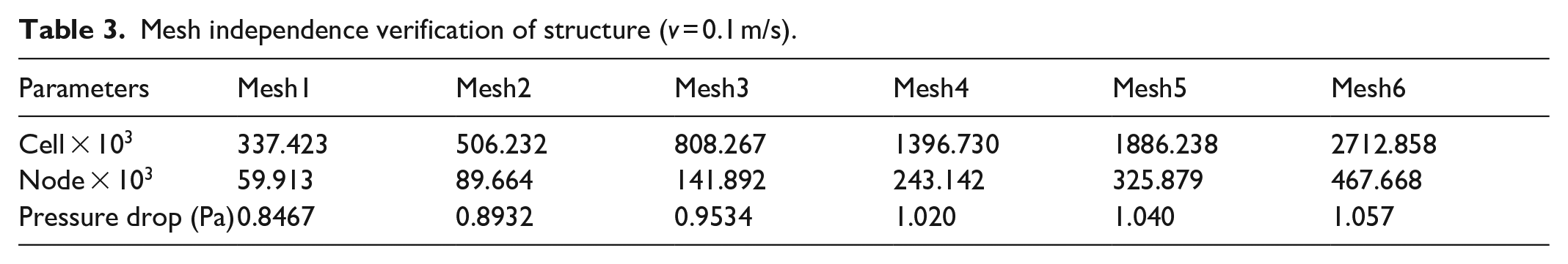
In the simulation, the fibrous structure used hexahedral mesh and refined the mesh on the fiber surface. The mesh dependence verification of the six sets of mesh numbers was carried out to eliminate the influence of the mesh number on the accuracy of the numerical simulation calculations. The corresponding results of mesh density analysis are shown in Table 3. With the increase in the mesh number, the pressure drop of the fibrous structure increased first and then leveled off. When the mesh number of the fibrous structure risen from 1.397 to 2.713 million, the pressure drop changed by 3.627%. The mesh numbers for other meshes such as Mesh1, Mesh2, Mesh3, and Mesh5, increased to 2.713 million were altered by 24.84%, 18.34%, 9.801%, and 1.635%, respectively. Under consideration of the mesh numbers and relative errors, the mesh number of the fibrous structure was set at 1.397 million.
Mesh independence verification of structure (v = 0.1 m/s).
Pressure drop verification
Figure 3 shows the comparison of the pressure drop between the numerical simulation and empirical formula. The pressure drop was linearly proportional to the inlet velocity. The difference in the pressure drop increased with increasing inlet velocity, which was consistent with the results of the Darcy equation calculated using four empirical formulas.31–34 The pressure drop in the numerical simulation was between the Darcy equation values calculated using the Kuwabara and Happel empirical formulas. When the inlet velocity was 0.1 m/s, the error between the numerical simulation and Darcy equation calculated with the empirical formula of Kuwabara was 8.5%.

Comparison of the pressure drop between the numerical simulation and empirical formulas.
Filtration efficiency verification
The filtration efficiency of a filter medium can be obtained in terms of its thickness (L), solid volume fraction (α), fiber diameter (df), and total single fiber efficiency (SFE). The filtration efficiency of a fibrous filter can be calculated as follow2,8,35:


where the total SFE, E ∑ , is the sum of the SFEs due to Brownian diffusion (ED), interception (ER), 11 and inertial impaction (EI). 9
The filtration efficiencies obtained from the numerical simulation and empirical formulas are compared in Figure 4. It was found that the filtration efficiency increased as the number of inlet particles increased. When the number of inlet particles was 500, the numerical simulation of the filtration efficiency was consistent with the empirical formulas. Figure 4 also shows that the filtration efficiency increased with the increase in particle diameter when dp > 1.0 μm. Despite some deviations in the numerical simulation, the errors between the numerical simulation and empirical formula were within 10%. Moreover, this research made a quantitative comparison to verify the UDF of the magnetic field force, which was within the acceptable range. 36 At the same time, the locations of the magnetic attraction zones and the magnetic repulsion zones on the magnetic fiber in simulation results were the same as those previously reported.21,22

Comparison of the filtration efficiency between the numerical simulation and empirical formula.
Results and discussion
The interaction between orthogonal magnetic fibers under Situation 1
Figure 5 shows the interaction between orthogonal magnetic fibers under Situation 1. No.2 magnetic fiber inhibited the capture of Fe-based fine particles by No.1 magnetic fiber, and the degree of reduction in filtration efficiency was approximately 12%–20%. No.1 magnetic fiber also inhibited the capture of Fe-based fine particles by No.2 magnetic fiber, and the degree of reduction in filtration efficiency was approximately 0%–10%. These results show that the inhibitory effect of No.2 magnetic fiber is greater than that of No.1 magnetic fiber. According to the trajectory diagram of Fe-based fine particles, there are two magnetic attraction zones and two magnetic repulsion zones around No.1 magnetic fiber. The magnetic attraction zones are located on the windward and leeward sides of the magnetic fiber. Due to the magnetic fields around the two magnetic fibers are the same, the force fields generated are also the same. The rightward magnetic attraction force generated by No.2 magnetic fiber enhanced the magnetic force acting on Fe-based fine particles on the windward side of No.1 magnetic fiber, which caused disorders in particle trajectory before being captured by magnetic fiber. However, the rightward magnetic attraction force generated by No.2 magnetic fiber also enhanced the flow of the Fe-based fine particles, which shortened the period at which Fe-based fine particles were captured by No.1 magnetic fiber. Therefore, No.2 magnetic fiber has an inhibitory effect on No.1 magnetic fiber. Meanwhile, No.2 magnetic fiber has a stronger inhibitory effect than No.1 with the same magnetic field. The reason is that after the particles were captured by No.1 magnetic fiber, the number of particles decreased. When the particles were captured by No.2 magnetic fiber, the number of particles affected by No.1 magnetic fiber reduced. The number of particles affected by No.2 magnetic fiber was more than that of No.1 magnetic fiber, so the inhibition was more prominent.
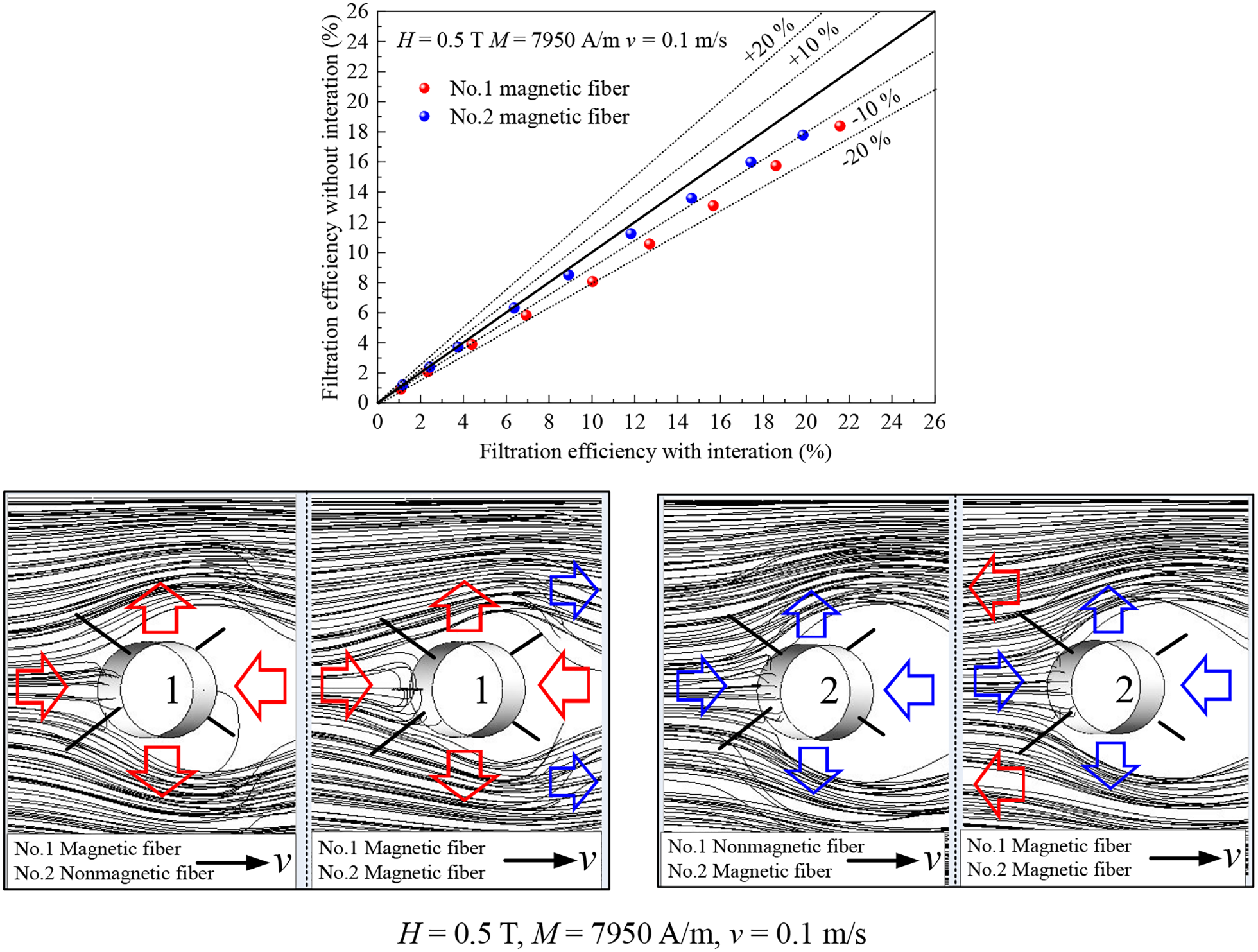
The interaction between orthogonal magnetic fibers under Situation 1. The red and blue arrows indicate the force generated by No.1 magnetic fiber and No.2 magnetic fiber, respectively.
The interaction between orthogonal magnetic fibers under Situation 2
Figure 6 shows the interaction between orthogonal magnetic fibers under Situation 2. When the saturation magnetization of the magnetic fibers was 79,500 A/m, No.2 magnetic fiber inhibited the capture of Fe-based fine particles by No.1 magnetic fiber, and the degree of reduction in filtration efficiency was approximately 27%–36% (Figure 6(a)). When the saturation magnetization was 7950 A/m, the degree of reduction was approximately 0%–34% (Figure 6(a)). The degree of inhibition was affected by the saturation magnetization of the magnetic fiber. As shown in Figure 7(a), the inhibition of particle capture may be attributed to the leftward magnetic repulsion force generated by No.2 magnetic fiber, which weakened the capture of the Fe-based fine particles by No.1 magnetic fiber on the windward side.

The interaction between orthogonal magnetic fibers under Situation 2. • represents magnetic fiber; ○ represents traditional fiber. (a) The filtration efficiency of No.1 magnetic fiber; (b) and (c) The filtration efficiency of No.2 magnetic fiber.

Trajectory diagram of Fe-based fine particles captured by magnetic fibers when a uniform magnetic field was added along the Y-axis (H = 0.5 T, M = 79,500 A/m, v = 0.1 m/s). (a) Trajectories of particles captured by No.1 magnetic fiber; (b) Trajectories of particles captured by No.2 magnetic fiber.
When the saturation magnetization was 79,500 A/m, No.1 magnetic fiber inhibited the capture of Fe-based fine particles by No.2 magnetic fiber at interval I but promoted capture at interval II (Figure 6(b)). As shown in Figure 7(b), the inhibition of particle capture is attributed to the leftward magnetic attraction force generated by the No.1 magnetic enhanced the magnetic repulsion force generated by No.2 magnetic fiber on the windward side. In addition, the magnetic attraction force acting on the Fe-based particles was small as the particles passed through the attraction zones of No.2 magnetic fiber. The small particles had a good following in the flow field, which increased the difficulty of capture by No.2 magnetic fiber. The promotion is due to the magnetic field force acting on the particles increases. The leftward magnetic attraction force generated by No.1 magnetic fiber could offset a portion of the flow drag force acting on Fe-based fine particles as the particles passed through the attraction zones of No.2 magnetic fiber. The longer duration of passage through the attraction zones of No.2 magnetic fiber reduced the difficulty in capturing particles. At a saturation magnetization was 7950 A/m, the interaction between orthogonal magnetic fibers was not apparent (Figure 6(c)).
Figure 7 shows the trajectory diagram of Fe-based fine particles captured by magnetic fibers when a uniform magnetic field was added along the Y-axis. Figure 7(a) shows the magnetic attraction zone around No.1 magnetic fiber. The interaction between orthogonal magnetic fibers shifted the trajectories of the Fe-based fine particles captured by No.1 magnetic fiber and reduced the deposition area. Moreover, the trajectories of the larger particles on the windward side of No.1 magnetic fiber were also more disordered. The magnetic field around No.2 magnetic fiber greatly influenced the magnetic field of No.1 magnetic fiber. The reason is that the magnetic field generated by No.2 magnetic fiber is in the same plane as the external uniform magnetic field. The two magnetic fields could be superimposed vectorially on a plane perpendicular to the magnetic fiber axis to strengthen the surrounding magnetic field.
Figure 7(b) shows the two magnetic attraction zones and two magnetic repulsion zones around No.2 magnetic fiber. Regardless of the particle diameter, the interaction between orthogonal magnetic fibers did not change the trajectories of the Fe-based fine particles captured by No.2 magnetic fiber and the location of the deposition points. Therefore, the shape of the “cavity,” (i.e. the particle-free area formed around the magnetic fiber by the repulsive force as the particles passed through the magnetic fiber) did not change. The magnetic field generated around No.1 magnetic fiber weakly influenced No.2 magnetic fiber. This is because the magnetic field generated by No.1 magnetic fiber and the external uniform magnetic field could not be superimposed vectorially on a plane perpendicular to the magnetic fiber axis.
The interaction between orthogonal magnetic fibers under Situation 3
Figure 8 shows the interaction between orthogonal magnetic fibers under Situation 3. When the saturation magnetization of the magnetic fibers was 79,500 A/m, No.2 magnetic fiber inhibited the capture of Fe-based fine particles by No.1 magnetic fiber (Figure 8(a)). The filtration efficiency of the Fe-based fine particles captured by No.1 magnetic fiber was 0 when dp ⩾ 1.5 μm. As shown in Figure 9(a), the rightward magnetic attraction force generated by No.2 magnetic fiber changed the shape of the “cavity” and the location of the deposition points. At the same time, the rightward magnetic attraction force enhanced the flow of Fe-based fine particles and reduced the duration for the passage of Fe-based fine particles through the attraction zone of No.1 magnetic fiber. Therefore, the filtration efficiency of the Fe-based fine particles captured by No.1 magnetic fiber was reduced. When the saturation magnetization was 7950 A/m, No.2 magnetic fiber had the same effect on No.1 magnetic fiber despite the small saturation magnetization of the magnetic fiber (Figure 8(b)). The reason is that the attraction force in the attraction zone of No.1 magnetic fiber is perpendicular to the direction of the flow field and the small deposition area of No.1 magnetic fiber, which is susceptible to the influence of the flow field. Moreover, the rightward magnetic attraction force generated by No.2 magnetic fiber enhanced the flow of the Fe-based fine particles.

The interaction between orthogonal magnetic fibers under Situation 3. • represents magnetic fiber; ○ represents traditional fiber. (a) and (b) The filtration efficiency of No.1 magnetic fiber; (c) The filtration efficiency of No.2 magnetic fiber.

Trajectory diagram of Fe-based fine particles captured by magnetic fiber when a uniform magnetic field was added along the Z-axis (H = 0.5 T, M = 79,500 A/m, v = 0.1 m/s). (a) Trajectories of particles captured by No.1 magnetic fiber; (b) Trajectories of particles captured by No.2 magnetic fiber.
When the saturation magnetization of the magnetic fibers was 79,500 A/m, No.1 magnetic fiber promoted the capture of Fe-based fine particles by No.2 magnetic fiber, and the degree of increment in filtration efficiency was approximately 3.5%–34% (Figure 8(c)). When the saturation magnetization was 7950 A/m, the degree of increment was approximately 0%–25% (Figure 8(c)). The magnitude of increase was affected by the saturation magnetization of the magnetic fiber. As shown in Figure 9(b), the rightward magnetic repulsion force generated by No.1 magnetic fiber enhanced the capture of the Fe-based fine particles by No.2 magnetic fiber on the windward side. Moreover, the decrease in the number of particles captured by No.1 magnetic fiber increased the probability of capture by No.2 magnetic fiber.
Figure 9 shows the trajectory diagram of Fe-based fine particles captured by magnetic fiber when a uniform magnetic field was added along the Z-axis. Figure 9(a) shows the two magnetic attraction zones and two magnetic repulsion zones around No.1 magnetic fiber. The interaction between orthogonal magnetic fibers changed the “cavity” and the location of the deposition points. The change in the “cavity” was more evident with the increase in the particle diameter, preventing the deposition of particles on the fiber surface. Figure 9(b) shows the magnetic attraction zone around the No.2 magnetic fiber. The interaction between orthogonal magnetic fibers changed the trajectories of the Fe-based fine particles captured by No.2 magnetic fiber and increased the deposition area. The strength of the magnetic field by No.2 magnetic fiber was smaller than that of No.1 magnetic fiber. In contrast, the magnetic field around No.2 magnetic fiber greatly influenced the magnetic field of No.1 magnetic fiber, contrary to the conclusion in Figure 7. This is because the degree of influence was not only affected by the strength of the magnetic field but also by the flow field.
The filtration efficiency of orthogonal fibers
Figure 10 shows an efficiency comparison between magnetic fiber-traditional fiber and traditional fiber-traditional fiber. It can be seen that the alternative use of magnetic fiber and traditional fiber could improve the ability of orthogonal magnetic fibers to capture Fe-based fine particles. When H = 0.5 T, M = 7500 A/m, the magnetic fiber (H x ) and the traditional fiber were used alternately, the filtration efficiency could be improved 10% and 9.0%, respectively.

Efficiency comparison between magnetic fiber-traditional fiber and traditional fiber-magnetic fiber.
However, the process of magnetic fiber (H z ) capturing Fe-based fine particles was greatly affected by the flow field, and the magnetic fiber intensity of H y was weak. 29 The alternative use of magnetic fibers (H y or H z ) and traditional fibers can improve the capturing efficiency of Fe-based fine particles, which requires high magnetic saturation magnetization. When H = 0.5 T, M = 75,000 A/m, the magnetic fiber (H y ) and the traditional fiber were used alternately, the filtration efficiency could be improved 8.5% and 8.4%; When H = 0.5 T, M = 75,000 A/m, the magnetic fiber (H z ) and the traditional fiber were used alternately, the filtration efficiency could be improved 14% and 10%. Moreover, the magnetic fiber (H z ) combined with the traditional fiber could significantly improve the filtration efficiency in the range of 0.5–1.5 μm.
Conclusions
This study investigated the influence of the interaction between orthogonal magnetic fibers on the capture of Fe-based fine particles by adjacent fibers. When a uniform magnetic field was added along the X-axis, the two perpendicular magnetic fibers affected each other by inhibiting the capture of Fe-based fine particles. The inhibitory effect of No.2 magnetic fiber was greater than that of No.1 magnetic fiber. When a uniform magnetic field was added along the Y-axis, No.2 magnetic fiber inhibited the capture of Fe-based fine particles by No.1 magnetic fiber. However, No.1 magnetic fiber could have different effect on the capture of Fe-based fine particles by No.2 magnetic fiber depending on the particle diameter and saturation magnetization. When a uniform magnetic field was added along the Z-axis, No.2 magnetic fiber inhibited the capture of Fe-based fine particles by No.1 magnetic fiber, whereas, No.1 magnetic fiber promoted the capture by No.2 magnetic fiber. Regardless of the combination sequence and combination type of magnetic fields, the magnetic field around No.2 magnetic fiber greatly influenced the magnetic field of No.1 magnetic fiber. Therefore, the magnetic filter material is suitable for the weaving method for the alternate use of magnetic fibers and traditional fibers to reduce the effects of the interaction between magnetic fibers on the capture of Fe-based fine particles.
Footnotes
Declaration of conflicting interests
The author(s) declared no potential conflicts of interest with respect to the research, authorship, and/or publication of this article.
Funding
The author(s) disclosed receipt of the following financial support for the research, authorship, and/or publication of this article: This work was supported by the National Key Research and Development Program of China (2018YFC0705300); the Special Funds and Key Projects of Fundamental Scientific Research Business Fees in Central Universities (2232017A-09); the Fundamental Research Funds for the Central Universities and Graduate Student Innovation Fund of Donghua University (CUSF-DH-2020067); and the Lanzhou Talent Innovation Project (2019-RC-7).