
Abstract
Cement is commonly used in the rapid construction of emergency airports; however, cemented soils have issues with integrity and crack resistance. For example, cemented soils can crack easily, and overall stability is insufficient. To address these problems, cemented soil is reinforced with hybrid polypropylene fiber, and the anti-flying property, anti-wear property, and crack resistance of polypropylene fiber reinforced cemented soil with varying fiber lengths, fiber contents, and fiber combinations are examined through flying tests, wear tests, and crack tests. Results show that the reinforcement of fiber can significantly improve the anti-flying property, anti-wear property, and crack resistance of cemented soil. The content and fiber length have a great impact on properties of fiber reinforced cemented soil. The ideal length and content of fine polypropylene fiber are 12 mm and 0.3%, respectively. The ideal combination of hybrid polypropylene fiber reinforced cemented soil is 0.3% coarse polypropylene fiber with the length of 38 mm and 0.3% fine polypropylene fiber with the length of 12 mm. In addition, hybrid polypropylene fiber reinforced cemented soil mechanical properties exceed those of single polypropylene fiber reinforced cemented soil.
Introduction
Cemented soil is easily constructed, is economic, and has an abundance of available raw materials, which makes it suitable for use in the rapid construction of emergency airports. However, cemented soil has some drawbacks, such as easy cracking and insufficient overall stability. Cracking of cemented soil is caused by shrinkage cracks in the soil itself, which are easily produced in a dry climate and may be a direct or indirect inducer of numerous engineering geological problems. The occurrence and development of cracks decreases soil strength, destroys soil integrity, increases soil permeability, and allows rain to more easily enter the soil mass, causing greater damage. For example, cracks can accelerate slope instability and induce landslides or mudslides. As a result, a series of studies on clay cracks have been conducted by numerous scholars. Qualitative and quantitative analysis are two methods of studying dry shrinkage cracks in soil. Qualitative analysis primarily uses various models to simulate soil cracking and calculates parameters such as cracking moisture content, crack initiation time, secondary crack initiation time, crack network curvature, and surface crack spacing.1–9 Quantitative analysis uses image processing technology to measure crack size (length, width, and depth),10–13 crack intensity factor,14–16 surface cracking rate, 17 and crack tip opening angle, 15 which are used to analyze to geometric morphology of soil cracks.
Since emergency airports need to ensure the flight of particular aircrafts for several months or even several years, so there is an urgent need to find an effective method of improving cemented soil durability. Presently, a novel method is to add natural and or synthetic fiber to the cemented soil. The natural fiber was uses as early as 5000 years ago. At that time, humans discovered that plant fiber can increase soil strength and stability in natural slopes.18–21 Current research on natural fiber primarily includes coir fiber, 22 sisal fiber, 23 palm fiber, 24 and wheat straw. 25 Plant fiber can improve soil stress conditions and increase soil strength; however, it is susceptible to corrosion in cemented soil. Research on synthetic fibers began in the last century, primarily including polypropylene fiber, glass fiber, polyethylene fiber, and polyester fiber. In terms of mechanical properties, the addition of fiber can improve soil compressive, tensile, and shear resistance.26–29 The current research focuses on the anti-cracking properties of synthetic fiber reinforced soil. Chaduvula 29 studied the crack resistance of polyester fiber reinforced expanded clay with varying fiber content and length using a digital image acquisition and processing system to conduct a quantitative crack analysis. Results showed that synthetic fiber enhanced the relative integrity of specimens. Polypropylene fiber can improve the crack resistance of clay to a certain degree, and as fiber content increases, surface crack rate and average crack width and length decrease, but fiber length has little effect on crack mechanical properties. 30 Polypropylene fiber can significantly suppress the occurrence and development of dry cracks. 16 The addition of fiber can effectively improve the crack resistance of fine-grained soil, and longer fibers can suppress cracks more effectively. 31
A single type of fiber can often significantly enhance one or several properties of the material, but generally it also has its own problems. For example, the filament fiber can improve the tensile strength and crack resistance, but it has the problem of poor dispersion. Therefore, researchers have mixed different types of fibers to make full use of the reinforcing effect of each fiber, especially in the field of concrete. Including steel-steel hybrid fiber, steel-polymer hybrid fiber, polymer-polymer hybrid fiber, and polymer-natural hybrid fiber.32–34 Results show that hybrid fibers can improve the toughness, ductility, energy absorption capacity, and durability performance of concrete. Long, thick macrofibers are blended with short, thin mesofibers and microfibers, to enhance the ductility of Ultra-High-Performance Fiber-Reinforced Cement-Based Composites, results show that the wollastonite microfibers are effective in increasing the ductility of UHP-FRCC, even under uniaxial tension.33–36 Studies have shown that fine and coarse polypropylene fibers play a major role in preventing the early and late stages of concrete cracking, respectively, which is in line with the demand for anti-cracking properties of the emergency airport. Therefore, the blending of coarse and fine polypropylene fibers have application potential in the construction of emergency airport.37–39
Polypropylene fiber can effectively enhance the crack resistance of concrete and plain soil, but few studies exist on the crack resistance of coarse polypropylene fiber and hybrid polypropylene fiber reinforced cemented soil. This contribution presents a crack test that quantitatively examines the crack resistance of coarse polypropylene fiber, fine polypropylene fiber, and hybrid polypropylene fiber reinforced cemented soil. Simultaneously, fiber reinforced cemented soil base would directly bear aircraft load in the case of simple surface layer damaged. If the integrity, anti-flying property, and anti-wear property of fiber reinforced cemented soil is weak, diseases, such as peeling, falling particles, and scattering, would be produced in base under the wheel load action repeatedly, which seriously affects the normal and safe aircraft operation. Currently few studies exist on the integrity and anti-wear of the fiber reinforced cemented soil. This contribution also presents a flying test and wear test to study the integrity and anti-wear properties of the fiber reinforced cemented soil, using the asphalt mixture fly test method 40 and cement mortar wear test method. 41
Materials and methods
Material characterization
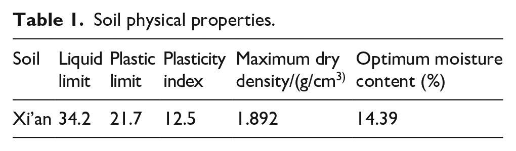
Materials were sourced from a variety of locations. Soil samples were taken from a low liquid limit clay in Xi’an in China (Figure 1) (Table 1).

Soil particle size curve.
Soil physical properties.
The parameters of coarse and fine polypropylene fibers (hereinafter referred to as coarse fiber and fine fiber respectively (Figure 2)) are shown in Table 2. The fiber parameters used in each test are shown in Table 3.
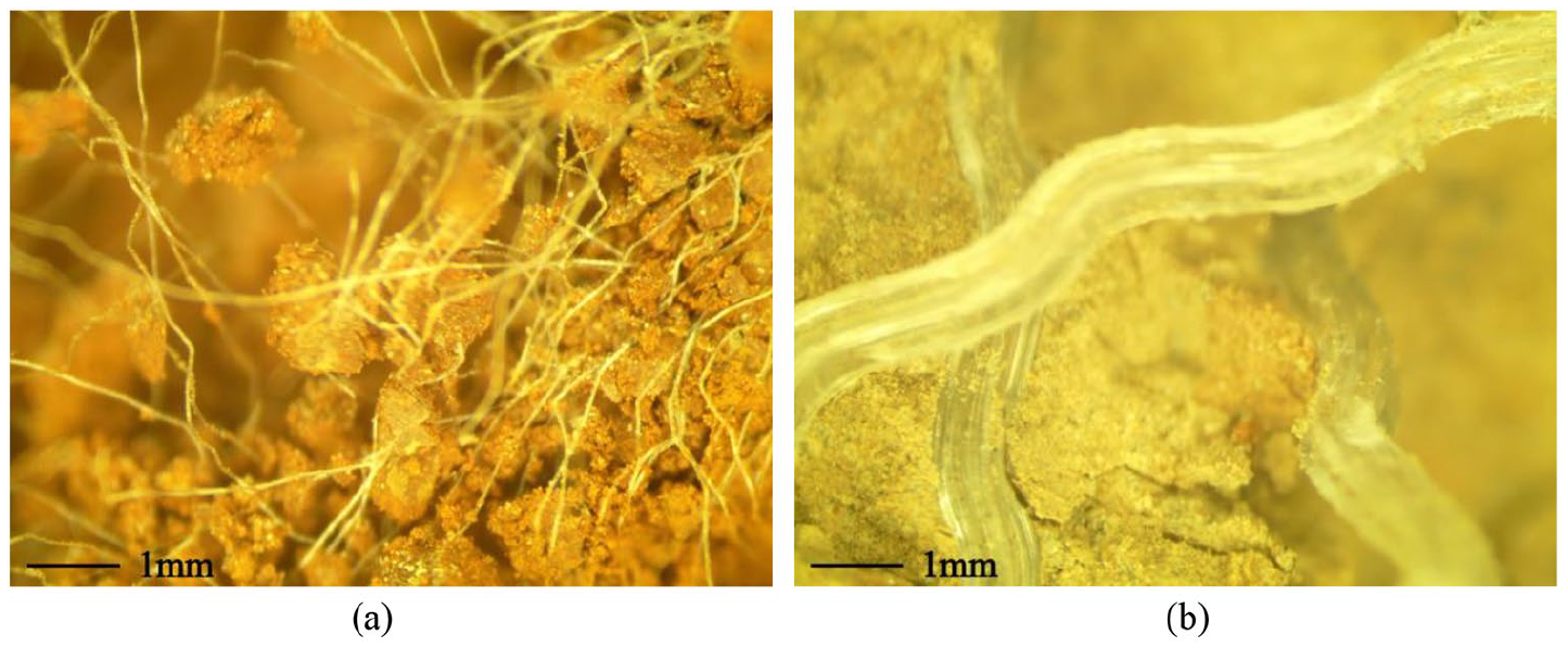
The size of fiber used in this paper: (a) fine fiber and (b) coarse fiber.
Fine and coarse polypropylene fiber physical properties.

Fiber parameters used in each test.

P.O 42.5 ordinary Portland cement (3.10 g/cm3) with a cement content of 8% (calculated as dry soil mass percentage) is used in the test. The maximum dry density of constructed cemented soil is 1.881 g/cm3, and the optimum moisture content is 14.44%. In addition to studying the effect of compaction degree on the crack resistance of fiber reinforced plain soil, specimens are constructed using static compression based on the optimum moisture content and maximum dry density. Forms of flying test and wear test specimens were cylinder with a diameter and height of 100 mm × 67 mm and 150 mm × 50 mm respectively. Crack test specimens are rectangular parallelepiped with a length, width, and height of 250 mm × 250 mm × 48 mm.
Curing methods include conventional curing and water immersion curing. Conventional curing was carried out in a curing box throughout the curing time. The temperature was set to 18°C–22°C, and the relative humidity was above 95%. Expect for the last day of the entire curing age, water immersion curing was the same as conventional curing, and for water immersion curing, the specimens are cured in a constant temperature water tank (20°C) in the last day of the age. Flying test specimens were cured using the conventional and water emersion methods for 7 days. Wear test specimens were cured for 7 days using the conventional method. The crack test specimens were cured using the conventional method. The curing time for plain soil and fiber reinforced plain soil samples was 7 days, and the curing time of cemented soil and fiber reinforced cemented soil is 1, 7, and 28 days. Each group contains three specimens, in which outliers are eliminated if they exceed three times the mean variance. The coefficient of variation Cv (%) of the same group should be less than 6%.
Flying test
The application background of this research is an emergency airport. If the integrity of the fiber reinforced cemented soil is not strong, the pavement surface will be peeled and scattered under the action of the wheel load, which will seriously affect the safe operation of the aircraft. Therefore, to be applied to emergency airport pavements, fiber reinforced cemented soil should have good integrity. At present, there is no integrity evaluation method for soil or solidified soil. Here, refer to the Kentucky Flying Test of Asphalt Mixture. 42 This method is used to evaluate the degree of aggregate shedding and loss on the road surface under the action of traffic load. It is expressed as the percentage of the mass of the scattered material of the asphalt mixture sample by the specified number of rotations and impacts of the sample in the Los Angeles tester. The test process is shown in Figure 3.

Process of flying test: (a) Los Angeles tester, (b) sample before test, and (c) sample after test.
The specific fiber usage is shown in Table 3. The test need to fly six times in total, and one time includes 20 turns. The graded flying loss ∆Si (equation (1)) and the total flying loss ∆S (equation (2)) were evaluated during test.


mi: specimen residual mass after each flying (g), i = 1, 2, 3, 4, 5, 6.
Wear test
Referring the “Testing Regulations for Cement and Cement Concrete of Highway Engineering” (JTG E30-2005), 43 this paper examined the anti-wear property of fine fiber and hybrid fiber reinforced cemented soil using a cement mortar wear tester. The test process is shown in Figure 4.

Process of wear test: (a) wear tester, (b) sample before test, and (c) sample after test.
The specific usage of fiber is shown in Table 3. Abrasion wear was performed for 60 turns, and weighing was performed every 10 turns; The evaluation indices were the wear mass per unit area G (kg/m2) (equation (3)), graded wear mass per unit area Gi (kg/m2) (equation (4)), and wear depth ∆h (mm) (equation (5)).

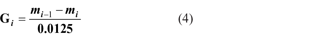

mi: specimen residual mass after each wear, i = 1, 2, 3, 4, 5, 6;
0.0125: specimen wear area of;
h0 and h6: specimen height initially and after 60 turns respectively.
Crack test
The crack resistance of plain soil, cemented soil, fiber reinforced soil, and fiber reinforced cemented soil is examined in this paper. The specific research objects contain plain soil with different compaction degrees (85%, 90%, and 95%), separate coarse and fine fiber reinforced soil samples, separate coarse and fine fiber reinforced cemented soil samples with different ages and hybrid fiber reinforced cemented soil sample with different ages (Table 3).
Wet and dry cycle
Cracks in the specimens are generated by wet-dry cycles. Considering that the use time of emergency airports is usually very short, mostly within a few months, in this study, the age is set as 1, 7, and 28 days. The specimens reaching the end of their designated age (1, 7, and 28 days) are placed in an oven set to 60°C for 1 h, and a spray nozzle is used to simulate rain ((Figure 5(a)). The spray time is uniformly set for 5 min. After spraying is completed, the drying process is repeated, and the dried soil specimen is photographed ((Figure 5(b)), which completes one wet-dry cycle. In order to maintain the same conditions for image processing (segmentation thresholding is required). Changes in the natural light must be accounted for when photographing specimens. So we create a dark environment and a consistent artificial light source was used to ensure consistent lighting conditions for imaging specimens.

Images showing the test process: (a) spraying and (b) taking photos.
Crack image processing
To make test results more accurate, it is necessary to take measures to process specimen images. Matlab is used to perform grayscale image processing, binarization, noise reduction, and crack bridging. In order to eliminate the error caused by boundary conditions, only the 20 cm × 20 cm area in the center of the specimen is considered.
Grayscale processing
Matlab is used to remove the color from the image, adjust the image to grayscale mode, and remove gaussian noise interference as well as salt and pepper noise interference. Images before and after preprocessing are shown in Figure 6.

Graphic comparison of processing step 1: (a) before processing and (b) after processing.
Binarization processing
Matlab is used to select a gray threshold value to binarize the image using the threshold segmentation method. Black represents cracks and white represent area of uncracked soil. Before thresholding, the background image needs to be estimated and subtracted (Figure 7). To obtain the foreground target image, the original image is subtracted from the background image, and the otsu adaptive segmentation method is used to convert the target image into a binary image.

Graphic comparison of processing step 2: (a) before processing and (b) after processing.
Noise reduction processing
Due to the presence of fibers or other impurities in the specimen, the binarized image will have some “noise spots” represented by small black spots in the soil regions (white regions). These black spots are not real cracks and need to be removed using noise reduction technology (Figure 8).

Graphic comparison of processing step 3: (a) before processing and (b) after processing.
Crack bridging processing
Due to the presence of material in the cracks, such as soil particles and fibers, the binarized image may white areas in the original cracks. Here, the morphological operation is used to bridge broken crack.
Evaluation index
(1) The surface crack rate (R) is the ratio of the total crack area Scra to the total image processing area, which is obtained using Matlab.
(2) The maximum crack width (W) reflects the cracking degree of specimens and is manually read using a microscope. The specific method involves manually choose 10 cracks, which should be the widest cracks, then using a microscope to measure the maximum width of the 10 cracks.
Results
Flying test results
(1) The flying test results are shown in Figure 9. The addition of fibers can improve the anti-flying property of cemented soil to certain degree. In terms of flying loss, with increasing fine fiber content, the flying loss of fine fiber reinforced cemented soil specimens decreased and then increased with an optimal content of 0.3%. It is difficult to disperse too many fibers, making it easy to aggregate to form a weak surface, resulting in a decrease in anti-flying property. For hybrid fiber reinforced cemented soil, the enhancement corresponding to a 0.3% coarse fiber content is better than a 0.6% coarse fiber content.
(2) Additionally, fiber length can also influence anti-flying properties. Whether reinforced by fine fiber alone or reinforced by hybrid fiber, the enhancement is best when the fine fiber length is 12 mm. The flying loss of specimens after water immersion curing significantly increased, but after the addition of fiber, the flying loss of specimens cured in water and under the conventional condition is close to the optimal condition, indicating that the addition of fiber significantly improves the water stability of the cemented soil.
(3) The graded flying loss of fine fiber reinforced cemented soil with a fiber content of 0.3% under water immersion curing is shown in Figure 9(d). The flying loss of unreinforced cemented soil can be described in three stages: called the initial stage, the crushing stage, and the stable stage. In the initial stage, graded flying loss is low, and the material exfoliated from the specimen concentrates in the peripheral area of the specimen cross section. In the crushing stage, as the number of impacts increases, the overall damage to the specimen intensifies, and the specimen breaks into several large fragments, and the flying loss increases rapidly. In the stable stage, the several large fragments attain a new stable stage, and the flying loss returns to a low level. However, for fine fiber reinforced cemented soil, the graded flying loss remains at a low level, except when the fiber length is 24 mm, indicating that the fiber with proper content and length can improve the anti-flying property of the cemented soil throughout the flying process.
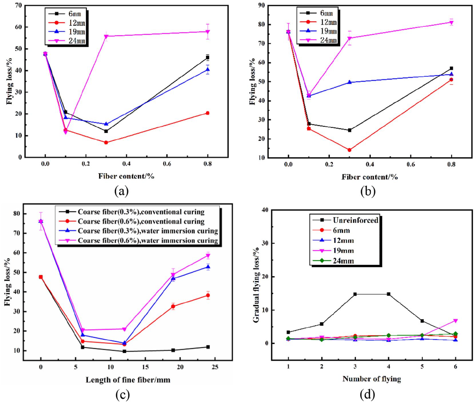
The flying loss and graded flying loss of fiber reinforced cemented soil: (a) conventional curing (fine fiber), (b) water immersion curing (fine fiber), (c) hybrid fiber, and (d) graded flying loss (0.3% fine fiber).
Wear test results
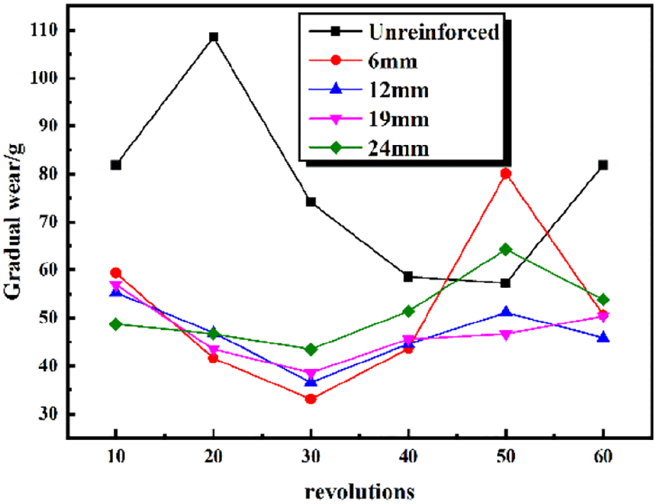
(1) The results of the wear test are shown in Figures 10 to 12. When the fiber length is 12, 19, and 24 mm, the mass loss of wear per unit area and wear depth of the fine fiber reinforced cemented soil decrease first and then increase, indicating that the anti-wear property enhances first and then weakens. When the fiber length is 6 mm, the anti-wear property always enhances because fine fiber has great dispersibility, and as fiber length decreases, dispersibility increases, so that fiber reinforcement increases.
(2) For hybrid fiber, when coarse fiber content is 0.3%, the enhancement of hybrid fiber reinforced cemented soil is better than when coarse fiber content is 0.6%, and as fine fiber length increases, the anti-wear property of two kinds of hybrid fiber reinforced cemented soil increases first but then decreases. The anti-wear property is best when the fine fiber length is 12 mm. In the optimal stage, the anti-wear property of hybrid fiber reinforced cemented soil is better than fine fiber reinforced cemented soil.
(3) From the point of view of the graded wear loss (Figure 12, fiber content = 0.3%), the graded wear loss curve is roughly divided into three phases: the stable wear phase, wear damage enhancement phase, and wear damage reduction phase. For the unreinforced cemented soil, the first 10 turns is the stable wear phase, 10–20 turns is the wear damage enhancement phase, and 20–40 turns is the wear damage reduction phase, and 40–50 turns is the stable wear phase. But for some specimens, 50–60 turns has been the wear damage enhancement phase again. However, for fine fiber reinforced cemented soil, the wear damage enhancement phase is delayed to 30–50 turns, and the grading wear loss of fiber reinforced cemented soil is generally lower than that of cemented soil for the same number of turns.
(4) When fiber length is 12 mm, the graded wear loss of fine fiber reinforced cemented soil minimized. The addition of polypropylene fiber can improve the anti-wear performance of cemented soil, and when 12 mm fine fiber (0.3%) is combined with 38 mm coarse fiber (0.3%), the enhancement of hybrid fiber reinforced cemented soil is maximized.

Wear of per unit area and wear depth of fine fiber reinforced cemented soil: (a) wear of per unit area and (b) wear depth.

Wear of per unit area and wear depth of hybrid fiber reinforced cemented soil: (a) wear of per unit area and (b) wear depth.
Graded wear loss of fine fiber reinforced cemented soil.
Crack test results
Crack test results for plain soil
The crack test results are shown in Figures 13 to 16. Figures 13 and 14 are the test results for plain soil, fine fiber reinforced soil (fiber content is 0.2%, and fiber length is 12 mm), and coarse fiber reinforced soil (fiber content is 0.2%, and fiber length is 38 mm) at varying degrees of compaction. Results show that surface crack rate and maximum crack width of plain soil specimens and fiber reinforced soil specimens decreases with increasing compaction degree, indicating that increasing compaction degree can improve the soil crack resistance. When the compaction degree is 95%, compared to the plain soil specimen, after three cycles, the surface crack rate of the fine fiber reinforced soil specimen decreased by 30.4%, 37.0%, and 35.3%, respectively, and the maximum crack width decreased by 22.8%, 42.6%, and 46.9%, respectively. However, the surface crack rate of the coarse fiber reinforced soil specimen decreased by 51.3%, 51.9%, and 50.7%, respectively, and the maximum crack width decreased by 46.5%, 61.2%, and 63.7%, respectively. Coarse fiber increases crack resistance more than fine fiber.
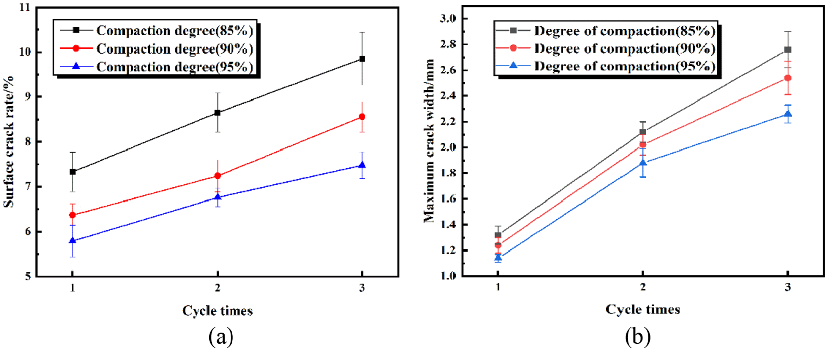
Surface crack rate and maximum crack width of plain soil: (a) surface crack rate and (b) maximum crack width.

Surface crack rate and maximum crack width of single fiber reinforced soil with varying compaction degree: (a) surface crack rate and (b) maximum crack width.

Surface crack rate and maximum crack width of fiber reinforced soil with varying fiber content: (a) surface crack rate and (b) maximum crack width.

Surface crack rate and maximum crack width of fiber reinforced soil with varying fiber length: (a) surface crack rate and (b) maximum crack width.
Figure 15 shows the surface crack rate and maximum crack width for fine fiber reinforced soil (fiber length is 12 mm and compaction degree is 90%) and coarse fiber reinforced soil (fiber length is 38 mm and compaction degree is 90%) with varying fiber content. As fiber content (⩽0.3%) increases, the surface crack rate and the maximum crack width of the coarse and fine fiber reinforced soil specimens gradually decrease, indicating that increasing fiber content within the range studied can enhance crack resistance. The two fiber types both have good dispersibility and can be sufficiently dispersed uniformly throughout the specimens.
Figure 16 shows the surface crack rate and maximum crack width for fine fiber reinforced soil and coarse fiber reinforced soil (fiber content is 0.3% and compaction degree is 90%) with varying fiber length. When the fiber length increases, the crack resistance of the fine fiber reinforced soil first increases and then decreases, and the crack resistance for 12 mm fine fiber reinforced soil is the largest. Crack resistance of coarse fiber reinforced soil increases with increasing fiber length because when making small specimens, the excessive length of the fiber is detrimental to fiber dispersibility, which increases the probability of fiber agglomeration. Fiber agglomeration is detrimental to the crack resistance; however the coarse polypropylene fiber has a very good dispersibility due to its own characteristics, so within the length range studied, the crack resistance of coarse fiber reinforced soil increases with increasing fiber length.
The crack test results for cemented soil
In cemented soil crack test, fiber content, fiber length, and compaction degree of fine fiber reinforced cemented soil are 0.3%, 12 mm, and 90%, respectively, and fiber content, fiber length, and compaction degree of coarse fiber reinforced cemented soil are 0.3%, 38 mm, and 90%, respectively. Cement curing significantly improves the crack resistance of the soil specimens, and reinforcement fibers improve the crack resistance of the cemented soil specimens even more (Table 4). The crack resistance of specimens increases with the age, and crack resistance also gradually increases. The crack resistance of fine fiber reinforced cemented soil is better than that of coarse fiber at 1 and 7 days, but the opposite is true at 28 days, indicating that fine fiber has a stronger inhibition to early cracking in the cemented soil, and coarse fiber has a stronger inhibition to later cracking of the cemented soil. Test result shows that hybrid fiber can significantly improve the early and late crack resistance of cemented soil.
Crack test results for various fiber reinforced cemented soils.

Destructive form analysis
The final forms of unreinforced cemented soil, fine fiber reinforced cemented soil, and hybrid fiber reinforced cemented soil specimens under respective optimal conditions in the flying test and wear test are shown in Figures 17 and 18, respectively. The hybrid fiber reinforced cemented soil specimens are the most intact, followed by the fine fiber reinforced cemented soil specimens, and the least intact are the unreinforced cemented soil specimens, once again showing that hybrid fiber yields the best result. In the wear test, the wearing wheel action surface is an annular wear surface with an inner diameter of 30 mm and an outer diameter of 130 mm (the specimen diameter is 150 mm). For the unreinforced cemented soil, the wearing wheel causes the edge to break during the wear damage enhancement phase, giving rise to drastic wear loss; but spalling in the edge of fiber reinforced cemented soil is quite low due to pull from the fibers. In the flying test, the appropriate fiber reinforced cemented soil specimens cured specimen stability with no fracture occurring. The damage is primarily spalling of cemented soil in the surrounding area, while the unreinforced cemented soil specimen broke into several relatively large fragments during the flying process, leading to tremendous loss. The damage is due to the fact that fibers with appropriate content and length can be interwoven into the soil structure, which serves to effectively cohere the soil and thus enhance soil integrity. As a result, the pulling effect between fibers and the cohesion and friction between fibers and the soil could offset the damage from wear and flying.

The final form of flying specimens after testing: (a) plain soil, (b) fine fiber, and (c) hybrid fiber.
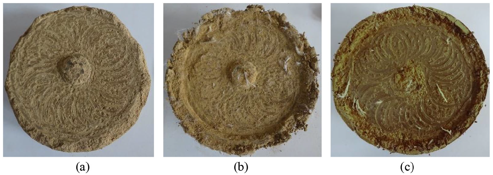
The final form of wear specimens after testing: (a) plain soil, (b) fine fiber, and (c) hybrid fiber.
Discussion
Soil fiber reinforcement can be explained by cohesion action, friction action, and interlocking action, and the three-dimensional network structure, which formed between fiber and plain soil, between fiber and cemented soil or between fiber and fiber.31,42–45 The enhancement of the three-dimensional network structure is primarily caused by the pulling action between fibers. The cohesive action is produced by the cohesion between fibers and cemented soil gelling particles. When there is relative sliding between the fiber and soil under the influence of external forces, friction will hinder soil deformation and reinforce the soil. When the fiber surface is rugged, soil particles embed in the fiber surface, producing an interlocking action. When fibers are crooked, soil reinforcement can also improve. Coarse fiber has an enhanced interlocking action because of its wavy surface. So when fiber content is the same, the enhancement of crack resistance from coarse fiber is stronger than fine fiber (Figures 14–16). To explain this, we could consider a crook as an enlarged surface unevenness. The mechanical properties of fiber reinforced cemented soil are better than fiber reinforced plain soil for three primary reasons. First, there is a gelling particle layer on the fiber surface, which can enhance the friction between fiber and soil. Second, gelling particles will be embedded in the fiber to produce an interfacial plowing action, 45 which can enhance the interlocking of fiber and soil. Thirdly, cohesion exists between the fiber and gelling particles. Compaction degree, fiber content, fiber length, age, and fiber blending all have an impact on soil mechanical properties, which will be described below.
Effect of compaction degree
Test results show that increasing compaction degree can enhance the crack resistance of plain soil and fiber reinforced soil, which is consistent with the research results obtained by Consoli and Lecompte et al.46–48 Different compaction degrees means different dry densities. Consoli et al. 47 studied the fiber reinforced sand with different dry density, and found that the overall stiffness and carrying capacity of fiber reinforced sand with a larger dry density is better. Lecompte et al. also found that increasing the compaction degree can significantly enhance the interface action between fiber and soil through coir fiber pullout tests.46,48 Summarizing previous studies, the enhancement of soil properties by compaction is primarily reflected in three aspects:
Firstly, a greater compaction degree means smaller porosity, and smaller porosity means increased contact area between the fiber and soil particles, which increase the cohesion and friction. Secondly, increasing compaction degree will increase fiber deformation, which will increase the mechanical interaction between the fiber and soil. 49 Thirdly, water acts as a lubricant on the fiber-soil interface and decreases the interfacial friction. 45 Increasing compaction degree will reduce the thickness of the water-lubricating layer at the fiber-soil interface, increasing the interfacial friction. Therefore, soil performance may be enhanced through increasing the compaction degree; but increasing compaction degree will inevitably lead to an increase in cost. Cost and performance should be considered simultaneously when we selecting compaction degree in engineering practice.
Effect of fiber length and fiber content
Fiber length and fiber content have an enormous influence on the anti-flying property, anti-wear property, and crack resistance of fiber reinforced cemented soil. In general with increasing fiber content, the anti-flying and anti-wear property of fiber reinforced cemented soil first increases and then decreases, which is consistent with results from previous studies.50,51 Fiber content can affect cohesion and friction between the fiber and soil by affecting the contact area between fiber and soil. When the fiber content does not exceed a certain amount, the fiber can be effectively dispersed; hence, larger fiber content indicates larger contact area and enhanced mechanical properties. When the fiber content is too large, fibers tend to aggregate, which does not effectively increase the contact area, producing a weak surface and reducing the fiber’s effectiveness.
Tang et al. 30 did not determine the effect of fiber length on the crack resistance of fiber reinforced soil; however, fiber length has a significant influence on the anti-flying, anti-wear properties and crack resistance. Except for the graded wear loss and wear depth of fine fiber reinforced cemented soil (Figure 9(b)), soil mechanical properties first increase and then decrease with increasing fiber length, which is consistent with previous test results.52–56 In terms of fine fiber reinforced cemented soil, the best properties are obtained when the fiber length is 12 mm, and the best crack resistance of coarse fiber is obtained when the fiber length is 48 mm.
Fiber length can influence the reinforcing effect by affecting the contact area, but the effect is less compared to the fiber content. When subjected to an external force, the action between different fibers and the soil take different destruction forms. When fiber length is short, destruction forms are characterized by fiber pull-out or sliding damage. When fiber length is large, destruction forms are characterized by fiber breakage. When fiber length is appropriate, the tensile stress on the fiber should be equivalent to fiber tensile strength so that the fiber-reinforcement is fully utilized. However, the excessively long fiber (like the excessively long polypropylene fiber in this experiment) will prevent fiber-dispersion in cemented soil, which relatively weakens the cohesion and friction between the fiber and cemented soil and also affects the formation of the three-dimensional network structure, thereby reducing the fiber reinforcement effect. Olgun 52 also found that the fiber reinforcement effect was reduced at a fiber length of 20 mm because a significant friction was not present between the long fibers and soil caused by flocculation and uneven dispersion.
Effect of age on crack resistance of fiber reinforced cemented soil
The crack resistance of fine fiber reinforced cemented soil exceeds that of coarse fiber reinforced cemented soil at 1 and 7 days, but the results are reversed at 28 days. However, no similar results are observed in fiber reinforced soil because is because the reinforcement of fiber reinforced soil derived from cohesion and friction between fibers and soil is low. In contrast, due to the special heterogenic structure of coarse fiber, there exists a bite force between coarse fiber and soil, offering a better reinforcement than fine fiber.
In terms of fiber reinforced cemented soil, when the age reaches 1 and 7 days, the cement induces a rapid hydration reaction, and the hydrate formed by the reaction increases the fiber-soil cohesion. Cohesion is the primary force at play at this time, and the cohesion between the fine fiber and soil is greater than the cohesion between the coarse fiber and soil at the same content, because fine fiber has a smaller size, leading to greater crack resistance in fine fiber reinforced cemented soil. When the age reaches 28 days, the hydration reaction has nearly completed, during this process, with the cemented soil gradually hardening, water is consumed and vaporizes. Capillary tension is present in the soil capillary pores, and the cemented soil shrinks under the effect of negative pressure. Assuming there is constraint outer boundary, the cemented soil will crack. For the same fiber content, fine fiber boasts more capillary pores than coarse fibers, leading to higher moisture dissipation rate. As a result, more shrinkage due to negative pressure is present, and the probability of cracking under the same conditions is higher for fine fiber reinforced cemented soil.
Hybrid fiber reinforcement
The anti-flying property and crack resistance of hybrid fiber reinforced cemented soil exceeds that of the single fiber reinforced cemented soil, and hybrid fiber reinforcement can improve the crack resistance in the early and late stages. The dispersibility of coarse and fine fiber is good, and with the adequate content and length, both fine fiber and coarse fiber can form a good spatial network structure inside the soil. Due to differences in fiber diameters, coarse fiber can form a large-scale spatial skeleton structure, while fine fiber can form a smaller scale spatial structure. A combination of the two serves to strengthen the soil. There also exists a bite force between the soil and coarse fiber with its special wave structure. 57 When fiber content is the same, the contact area between fiber and soil for fine fiber is larger than coarse fiber; hence, cohesion between the soil and fine fiber is greater than that of coarse fiber. So the combination of coarse and fine fiber can make full use of the two enhancement types. Soltani et al. 58 also found that hybrid fiber with different lengths and aspect ratio can enhance soil properties more effectively than single fiber.
Conclusions
In order to address problems with average cemented soil, such as easy cracking and insufficient overall stability, flying, wear, and crack tests on fiber reinforced cemented soil with varying fiber content, fiber length, and fiber combination were carried out, and the conclusions are as follows:
(1) The addition of fiber improves the anti-flying property and anti-wear property of cemented soil. The addition of appropriate amount of fiber can improve the anti-wear property of cemented soil far more than simply increasing the cement content. The fiber content should not be too high, preferably 0.3%, the length of fine and coarse fiber should be 12 and 38 mm, respectively. In the flying test, the sample flying loss can be roughly divided into three stages: initial stage, crushing stage, and stable stage. The ideal combination of hybrid polypropylene fiber is 12 mm fine polypropylene fiber with a content of 0.3% and 38 mm coarse polypropylene fiber with a content of 0.3%.
(2) Photos can be processed efficiently through photon graying, binarization noise reduction, and crack bridging using Matlab. Through image processing, we can accurately analyze the crack resistance of cemented soil using the surface crack rate and crack width as evaluation indices.
(3) Compaction degree has a significant influence on soil crack resistance, and increasing compaction degree can improve soil crack resistance. In engineering practice, the cost and performance requirements should be comprehensively considered to select the appropriate compaction degree.
(4) Curing also affects the crack resistance of fiber reinforced cemented soil. The enhancement of crack resistance from fine fiber exceeds that of coarse fiber in the early stage (1 and 7 days), while the result is reversed in the later stage (28 days), and the crack resistance of hybrid fiber reinforced cemented soil in early and later stages can be improved.
Footnotes
Declaration of conflicting interests
The author(s) declared no potential conflicts of interest with respect to the research, authorship, and/or publication of this article.
Data availability
All data, models, and code generated or used during the study appear in the submitted article.
Funding
The author(s) disclosed receipt of the following financial support for the research, authorship, and/or publication of this article: The authors gratefully acknowledge financial support from the China Postdoctoral Science Foundation (Grant No.2020M671485), Natural Science Basic Research Program of Shaanxi (Grant No.2020JQ-474), Jiangsu Planned Projects for Postdoctoral Research Funds (Grant No.2020Z321), and Natural Science Foundation of Jiangsu Province (Grant No.BK20200429), and Traffic Construction in Jiangxi Province (Grant No.2020H0047).