
Abstract
The quality of composite preform has great influence on its mechanical properties. Aiming at the problems of difficulty in robot teaching and unstable braiding angle in the process of braiding three-dimensional complex component, a control method of robot is proposed. Firstly, the mandrel is discretized to ensure that the axis of each discrete mandrel is perpendicular to the braiding point plane, and the orientation and direction of the tool center are calculated. Then, the take-up speed of the robot is calculated, so that the self-adjustment of the braiding angle can be realized in the braiding process. The experimental results show that the control method can effectively reduce the braiding angle error of variable cross-section mandrel within 2°, and can improve the quality of composite products in actual production.
Preface
In recent years, due to the characteristics of light weight, high temperature resistance and strong corrosion resistance, composites are often widely used in aerospace, civil engineering, automobile manufacturing 1 and other fields to replace traditional metal materials.
Composites are composed of fiber reinforcements known as preforms and resins. Braiding is an important process for preforming of composite materials, and its errors such as braiding angle error and coverage error directly affect the mechanical properties of composite materials. Among them, the braiding angle is the angle formed by the yarn and the axis direction of the mandrel. The braiding angle error is usually caused by factors such as the fluctuation of the spindle speed or take-up speed, the contact, and friction between the yarns, 2 the change of the cross-section of the mandrel, etc. Whether the material has the desired tensile behavior depends on the braid angle error; 3 The coverage is the ratio of the area of the fiber covered on the surface of the mandrel to the surface area of the mandrel that needs to be braided. The error is usually caused by the complex geometry of the mandrel or the error of the braiding angle. The coverage error will lead to local resin accumulation and increase nesting, resulting in the decrease of the mechanical properties of the braided fabric. 4
In this paper, the varying section mandrel with bending as shown in Figure 3 is studied. Similar mandrels are widely used in weaving products with complex geometry, such as robot arms, prosthetics, and hockey sticks. 5 Potluri et al. 6 proposed a model for fiber path on complex shape mandrel, but the model tends to woven fabrics, which is more suitable for circular braiding than using weaving and knitting to preform hollow composite materials with complex geometry. 7 For preforms with complex geometric structures using circular braiding, Rawal et al. 8 used virtual reality modeling to simulate yarns on core molds with various geometric shapes; Gondran et al. 9 proposed a take-up speed solution method and made feedback adjustment to it, but did not consider the change of braiding point position. In this paper, the robot holds the mandrel for braiding and cooperates with speed regulation. Theoretically, the composite preform can be braided into any shape. Therefore, in the process of braiding, the precise control of robot trajectory and speed has become one of the key issues that need to be solved urgently.
In the braiding process, most researches are focused on the mandrel with constant cross-section or straight center line, while the research on the mandrel with variable cross-section or bent center line is relatively few. Du and Popper 10 approximately divided the rotating curved surface mandrel with varying cross-section into a series of conical sections. After the user determined one of spindle speed or take-up speed according to external conditions, the other one was obtained by calculation and controlled accordingly. van Ravenhorst and Akkerman 11 established the yarn trajectory model, and generated the machine control data of the braiding process by solving the inverse motion. Fouladi et al. 12 proposed to braid the flat mandrel with elliptical guide ring, and established a theoretical system for this method. Hajrasouliha et al. 13 proposed a model to predict the braiding angle on any constant cross section. The braiding model proposed by Kessels and Akkerman 14 is suitable for the prediction of yarn trajectory on the mandrel with asymmetric cross-section changing along the center line.
At the same time, industrial robots are used in many special manufacturing fields because of their high degree of freedom and good flexibility. Guyader et al. 15 mentioned the use of industrial robots to assist braiding. In the process of braiding the mandrel of three-dimensional complex component, it is necessary to keep the mandrel continuously braiding vertically through the plane of the braiding point at a certain speed. Hans et al. 16 used finite element software to simulate the whole braiding process of industrial robot clamping mandrel. Monnot et al. 17 established the braiding model suitable for the mandrel of non-axisymmetric geometric shape and bending center line, and completed the braiding with industrial robots. Zhuo et al. 18 analyzed the offset of the mandrel after force in the braiding process by finite element method, and then compensated the robot end to improve the braiding accuracy, but it is difficult to transform the coordinate system of the mandrel with arbitrary curved three-dimensional complex component. Martinec et al. 19 analyzed the process of the robot end clamping mandrel through the winding head in fiber winding, and obtained the trajectory of the robot during operation through calculation, but did not consider the situation that the mandrel section changed constantly.
In the process of braiding three-dimensional complex component mandrel, the trajectory of the robot end is usually obtained by manual teaching, and it is obtained by calculation in some studies.18,19 These trajectories are obtained by ensuring that the center line of the mandrel is perpendicular to the guide ring plane at the moment of braiding, rather than perpendicular to the braiding point plane, there is a convergence length between the braiding point plane and the guide ring plane, which leads to the fact that the direction of the center line of the bending mandrel cannot keep vertical to the plane of braiding point all the time. Meanwhile, the convergence length required for the braiding of the variable cross-section mandrel is constantly changing. If the direction and orientation of the end of the robot are not adjusted, the braiding accuracy will be reduced and the braiding quality will be affected. Therefore, it is difficult to design the trajectory and speed of the robot to draw the mandrel of the three-dimensional complex component for braiding.
In the braiding process, the convergence length has a great influence on the braiding angle, 20 thus affecting the quality of the preform. Therefore, it is necessary to adjust the robot posture and take-up speed to compensate the braiding angle error. In this paper, a control method for braiding the mandrel of three-dimensional complex component is proposed. This method uses a fixed plane coordinate of the braiding point when calculating the trajectory of the robot, and does not need to consider the change of its convergence length. At the same time, the mathematical model of the take-up speed in the braiding process is established, and then the braiding angle error caused by the change of the cross-section is compensated by controlling the take-up speed. This method can effectively reduce the error of braiding the mandrel of three-dimensional complex component and improve the mechanical properties of the preform.
Calculation of robot end trajectory
Robot
Robot-assisted preform braiding is shown in Figure 1. The robot base coordinate system and tool coordinate system need to be considered in braiding process. The external conditions such as the position of the braiding machine are described in the base coordinate system, the coordinate axis is represented by x, y, z, and the shape of the mandrel is described in the tool coordinate system, the coordinate axis is represented by xTool, yTool, zTool. When establishing the tool coordinate system, its position and posture can be arbitrary. In this paper, the direction that the tool coordinate system is perpendicular to the flange center point outward is the positive direction of zTool-axis. After calculating the pose of tool center point (TCP), the trajectory of the robot is written through the instruction library. TCP includes six values of x, y, z, a, b, and c, where x, y, and z are position information of the origin of the tool coordinate system in the base coordinate system; a, b, and c represent the rotation angles of the tool coordinate system around zTool-axis, yTool-axis, and xTool-axis with regard to the base coordinate system. The TCP value at a certain time in the process of robot movement is shown in Figure 2.
Robot and two dimensional braiding machine.

The relationship between base coordinate system and tool coordinate system.
Braiding model
The braiding process of a bending mandrel with variable cross-section is shown in Figure 3. The trajectory of the robot needs to ensure that the mandrel is always perpendicular to the plane where the braiding point is located. The coordinates of the braiding point S = [xs, ys, zs] and the vector perpendicular to the plane where the braiding point is located are set as

The braiding process.

Approximate the i-th segment mandrel with a cylinder in tool coordinate system.
In the formula, ro(i–1) and ro(i) represent the radius of the mandrel section at O(i–1) and O(i), respectively. Meanwhile, the unit axial vector
(1) The cylinder length d satisfies the robot’s response to each segment.
(2) The number of discrete points n has sufficient precision to define the shape of mandrel.
Robot end trajectory
At present, most of the known robot-assisted braided preform processes get trajectories by making the robot pass through the braided ring plane vertically at any time. Such trajectories have no effect on the linear mandrel, but for the bending mandrel, there is a braiding angle error, and the robot clamps the mandrel vertically through the guide ring at all times. Due to the convergence distance h, the center line of the mandrel cannot be perpendicular to the braided point plane at that time, resulting in the problem of unequal braiding angles on each side of the mandrel. For the mandrel with variable cross-section, a single trajectory planning cannot obtain a stable braiding angle, which affects the quality of composite materials. Therefore, in this paper, the trajectory compensation planning is carried out, and at the same time, different speed control is used for each trajectory to achieve the purpose of compensating braiding angle.
The trajectory of the robot end is determined by the data of TCP. In this paper, the mandrel is divided into N discrete points, and three TCP transformations are set between each discrete point. TCP1(i) (i = 1, 2,. . ., n–1) is the data after the rotation and translation angle φ changes. When braiding the i-th section, it is necessary to ensure that the vector

Flow chart of robot trajectory calculation.
Description of braiding process in base coordinate system.

End posture at different stages of braiding.
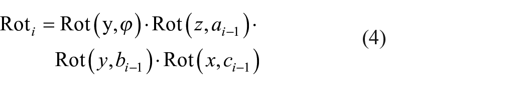
In the calculation process of TCP1(i), it is necessary to use the data xi–1, yi–1, zi–1, ai–1, bi–1, ci–1 in TCP3(i–1). Firstly, the vector

In the formula, Rot stands for rotation transformation, Rot(z, ai–1) is counterclockwise rotation angle ai–1 around z-axis, Rot(y, bi–1) is counterclockwise rotation angle bi–1 around y-axis and Rot(x, ci–1) is counterclockwise rotation angle ci–1 around x-axis. For the mandrel with the center line in the same plane, when clamping the mandrel, adjust the center line to the x–z plane, obtain the angle ϕ between
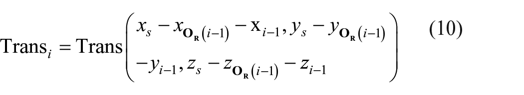
Since there is a distance between the center point of the tool and the discrete points on the mandrel, after rotation, it is necessary to make translation compensation along the z-axis and x-axis to make O(i–1) coincide with S point. The vector


In this formula,

For the mandrel whose center lines are not in the same plane, the corresponding rotation axis

For Rot(

In the formula, fx, fy, fz are the projection lengths of

In order to locate the TCP after the transformation, it is required to rotate the angle αi, βi, γi around the x-axis, y-axis, and z-axis in the base coordinate system, and the coordinates xi, yi, zi of the center point in the base coordinate system. The homogeneous transformation matrix is expanded as follows:

According to the homogeneous transformation matrix of (12), we can directly read the transformed position information px(i), py(i), pz(i) in the matrix, and add the position coordinates of the i–1th order to obtain the position information of the i–1th order. When solving the angle, we use the roll, pitch and yaw transformation solution (RPY) to solve. 21 The RPY angle is rotated around the coordinate axis of the fixed coordinate system. It is stipulated that the roll is rotated around the z-axis, the pitch is rotated around the y-axis, and the yaw is rotated around the x-axis. In the process of rotation, the tool coordinate system rotates γ around the x-axis of the base coordinate system, then rotates β around the y-axis of the base coordinate system, and finally rotates α around the z-axis of the base coordinate system. After the above rotation, the tool coordinate system can get the current posture. The expression is as follows:

In order to obtain the roll angle, pitch angle and yaw angle of the known transformation Ti, the following transformation is performed on equation (13):

By solving equation (14), the transformed RPY angle can be obtained as follows:

According to the above formula, we can calculate the position and direction information of the TCP of the robot end in the basic coordinate system, which is needed to braid the i-th mandrel. The forms of TCP1(i), TCP2(i), and TCP3(i) are as follows:


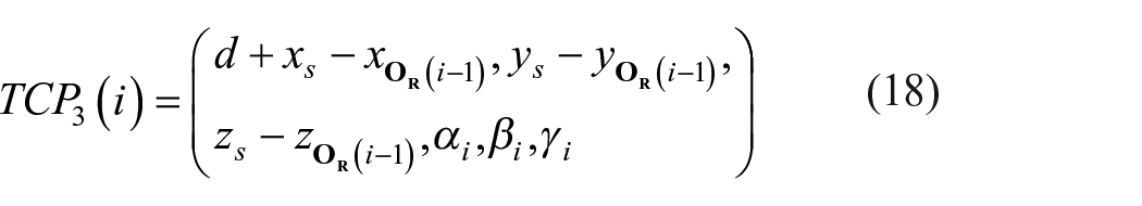
After obtaining the coordinates of TCP after three transformations, it is input into the robot command in turn, and the position and orientation data TCP3(i) = (xi, yi, zi, ai, bi, ci) of the stopping point of this movement is recorded and brought into the next calculation. According to the calculation process proposed in this paper, the robot take-up mandrel can be accurately braided and controlled to ensure that each mandrel vertically passes through the plane of braiding point.
Dynamic compensation model of braiding point
In the process of segment braiding with fixed mandrel at the end of the robot, the first stage is the rotation of the robot end, so that the i-th section of the mandrel maintains the posture of the vertical braided point plane for braiding. The second and third stages are the translation and propulsion of the robot. In the translation process, the d/2 is continuously moved forward based on the braided point plane. Because the cross-sectional area of the mandrel is constantly changing, according to the formula (19), 22 it can be seen that in the case of changing the cross-sectional radius of the mandrel, if the convergence length h is not adjusted, there will be a large error between the braiding angle and the expected value.

In the formula, θ is the braiding angle, which is the angle between the yarn and the center line of the mandrel; R is the radius of the guide ring, and the yarn is pulled out from the yarn carrier, and then braided after passing through the guide ring; r is the radius of mandrel; h is the convergence length, which is the length from the guide ring plane to the braiding point plane. The adjustment process of convergence length by using robots is complex. Since the motor of the braiding machine works continuously in the braiding process, it is impossible to use robot to adjust h by translation before each section starts braiding, and the braiding angle can only be adjusted by changing the take-up speed. In this paper, a mathematical model is established for the process of adjusting braiding angle by take-up speed.
Assumptions
For the braiding of three-dimensional complex component mandrel, the model proposed in this paper is based on the following assumptions:
(1) The friction and interaction force between yarns and between yarns and guide rings are ignored.
(2) The yarn thickness is neglected;
(3) The yarn is completely attached to the mandrel surface, and the yarn braided on the mandrel does not slide;
(4) Ignore the winding movement of the yarn carrier in the braiding process.
Braiding instability stage
In the braiding instability stage, there is a relative motion between the braiding point and the mandrel, and the relative speed is Vr. At the same time, the yarn is also braided on the mandrel at the speed Va, so

In the formula, V is the robot take-up speed. When the braiding is stable, the braiding point no longer moves, so Vr = 0, V = Va. The braiding speed Vs at expected braiding angle θ s is calculated by equation (21): 23

After the mandrel is divided into several sections according to the method shown in Figure 4, because the cross-sectional area of the mandrel is constantly changing, we need to adjust the robot take-up speed in the process of robot advancing the distance d, so that the braiding angle of the fabric approaches the desired one, and the braiding length of the yarn on the mandrel is also d, so that the i-th section has just finished braiding when the i-th section starts braiding, ensuring the continuity of braiding and the applicability of the discrete mandrel model. When the i-th segment is braided, due to the sudden change of radius, but the convergence length is still h0, the abrupt braiding speed Va0 can be calculated by formula (22) as follows:

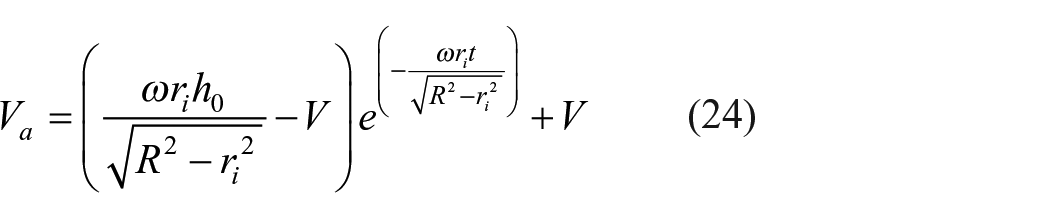
In the formula, ω is the angular velocity of the yarn carrier; ri is the section radius of the i-th mandrel; h is the convergence length, and h = h0 when each section starts braiding. In the unstable stage, the relationship between the moving speed Vr of braiding point and time t can be established based on the prediction model of braiding angle proposed by Wang et al.24 as shown in (23) (see Appendix A1 for the derivation process).

The relationship between braiding speed Va and time t is further obtained as follows:
It can be seen from the above formula that the robot’s take-up speed V has a great influence on the braiding speed Va of the fabric at a certain time point in the braiding process of the robot’s take-up mandrel. At the same time, it can be seen from the formula (21) that the take-up speed has a great influence on the braiding angle. At t time, we can get the function Va(V), and get the formula (25) by derivation of Va(V). It can be seen that the formula (25) is always greater than 0, so at t time, Va(V) is an increasing function (see Appendix A2 for the derivation process).

When the i-th segment of mandrel is braided, the change of the radius of the mandrel leads to Va0 ≠ Vs, so it is necessary to adjust the take-up speed of the robot to make the braiding speed quickly approach the expected braiding speed. It can be seen intuitively from Figure 8 that three different robot take-up speeds V, V
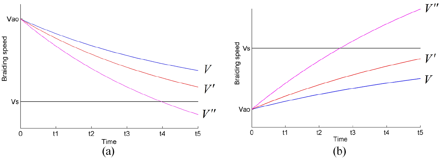
Curves of Va changing with time under different take-up speeds: (a) Va0 > Vs, V > V
Calculation of take-up speed
In the braiding process of composite preforms, in order to obtain a stable braiding angle on the three-dimensional complex component mandrel, we only need to ensure that the braiding angle approaches the expected angle on each section of the discrete mandrel model. Since the angular velocity ω of the spindle motion remains unchanged in the braiding process, controlling the take-up speed of the robot becomes the key to improving the accuracy when radius r of the mandrel changes. If the take-up speed calculated by formula (21) is directly input into the robot instruction, the mandrel is propelled at the speed of Vs, because Va0 ≠ Vs at the beginning of braiding process in the i-th segment of mandrel, there is an unstable stage. At this stage, the braiding point moves and the braiding angle gradually becomes the expected braiding angle θs. Within the same time, the braiding distance of the fabric cannot be equal to the advancing distance of the mandrel. This result is that the fabric length formed on the mandrel is not equal to d after the robot pushes the mandrel forward d, resulting in that the robot trajectory does not match the braiding process and cannot improve the braiding accuracy. If the speed of the robot is set to the abrupt braiding speed calculated by formula (22), the braiding point does not move and the robot enters the stable braiding stage, but the braiding angle calculated by formula (19) is not equal to θs, resulting in braiding error. In this paper, a control method is proposed to adjust the second and third stages of robot’s movement on each mandrel, and set the speeds to V1 and V2. V1 is mainly responsible for adjusting the convergence length to reach the convergence length hs of the expected braiding angle, and V2 is mainly responsible for adjusting the braiding length of the fabric to be equal to the advancing distance of the robot.
By integrating the formula (24), it is obtained that when the robot speed is V1, the relationship between the length l1 of braiding fabric formed by yarn on the mandrel and the time t is as follows:

When the robot speed is V2, the relationship between the length l2 of the braiding fabric formed by the yarn on the mandrel and the time t is:


In the formula, h1 is the convergence length after the robot moves at speed V1. Speed V1 and V2 need to meet the following constraints:


According to the above constraints, the two linear velocities V1 and V2 of the robot in the process of pulling the mandrel are obtained. After calculating the TCP point at the robot end in the process of mandrel braiding by Formulas (16)–(18), the speed calculated in this paper is input into the robot’s instruction to control the robot, which can make the mandrel pass through the braiding plane vertically at all times and ensure the stability of the braiding angle.
Experiment
In order to verify the applicability of the robot control method in braiding process proposed in this paper, taking the circular mandrel of three-dimensional complex component as an example. The model of the mandrel in robot tool coordinate system is shown in Figure 9, in which the mandrel is a right-angled tube with variable cross-section, and the thin rod is an elongated rod, which is not braided. The mandrel has a cross-sectional radius of 76.5 mm at the head end and 58.75 mm at the tail end, which is divided into 10 cylinders for sectional control. The equipment used in the experiment include radial braiding machine and six-degree-of-freedom industrial robot. The radial braiding machine is an 88-gear single-ring braiding machine, which includes 176 spindles, each spindle carries a bobbin for braiding, and the motion system of the braiding machine consists of four servo motors, two vibration motors and their controllers. In the braiding process, the rotation speed of the main machine is 600 rpm, the angular speed ω of spindle movement is 0.07 rad/s, and the frequency of vibration motor is 46 Hz. The trajectory and take-up speeds V1 and V2 of the robot are calculated by the algorithm proposed in this paper, as shown in Table 1 and Figure 10, and change with the cross-sectional area of the mandrel.

Geometric shape of mandrel.
Coordinate of TCP in robot program.


Speed of each section in braiding process.
When the braiding angle is 60°, the take-up speed of the robot for braiding the mandrel is shown in Figure 10. Table 2 shows the cross-sectional changes of each segment of the discrete mandrel. The take-up speed of the robot changes in two stages. Firstly, the braiding speed of the fabric is adjusted to be near the expected braiding speed, and then the distance is adjusted, so that the translation distance of the robot and the length of the formed fabric are both d. The larger the difference between the cross section of the discrete mandrel and the initial cross section, the larger the difference between the robot take-up speed V1 and the abrupt braiding speed Va0 during adjustment, so that the braiding speed can be quickly adjusted to the desired speed. In the process of adjustment, the braiding speed is always near the expected braiding speed, ensuring the stability of the braiding angle.
Radius of the i-th segment of discrete mandrel.

The preform braided by the traditional control method is shown in Figure 11. It can be seen from the figure that in the braiding process of traditional method, the yarn trajectory is seriously deviated because the convergence length is not considered in the robot trajectory, which leads to the problems that the direction of the connecting line formed by the intersection of warp and weft is not consistent with the center line of the mandrel, and the fabric is loose. At the same time, the traditional method of robot take-up speed does not consider the change of cross section, which leads to the inability to keep the braiding angle of preform constant. Using the control method proposed in this paper to braid the preform, the finished product is shown in Figure 12. It can be seen that the yarn on the preform is compact and the braiding angle is constant.

The preform braided by traditional method.
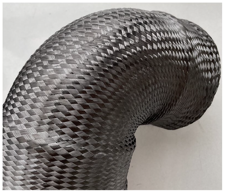
The preform braided by the optimal control method.
The braiding angles of the preforms braided by the two methods are compared. As can be seen from Figure 13, when the robot is assisted in braiding, the maximum difference between the braiding angle obtained by the traditional method and the expected braiding angle is more than 6°, which makes it impossible to obtain high-quality composite preforms. Using the control method proposed in this paper to adjust the position and posture of the robot and its take-up speed, the three-dimensional complex component mandrel can be braided accurately, and the braiding angle can float within 2°of the expected value, which improves the braiding efficiency and improves the mechanical properties of composite materials under the same conditions.
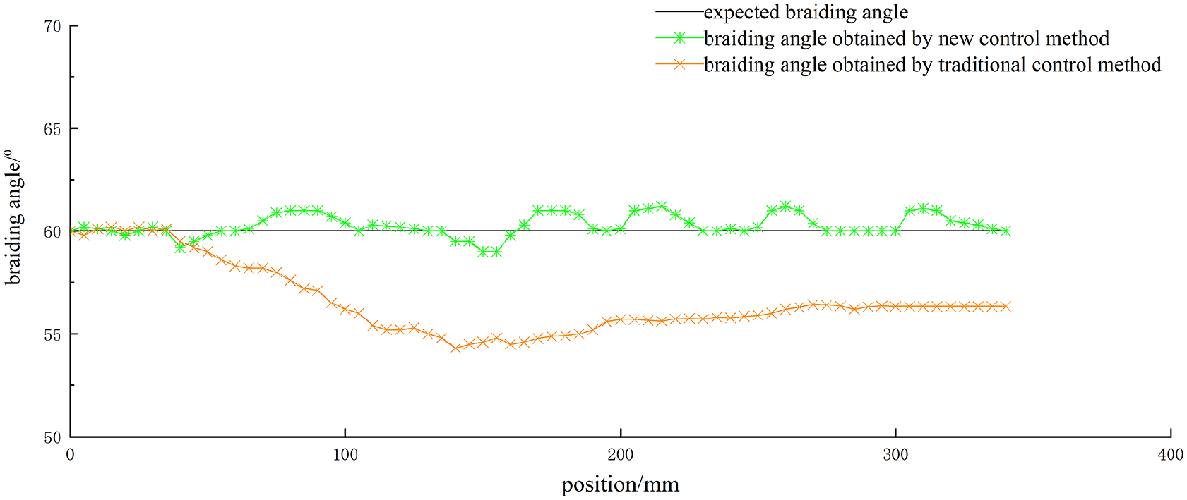
Comparison of theoretical braiding angle and braiding angle before and after optimal control.
Conclusions
In this paper, a control method in the process of robot-assisted braided composite preform is proposed. In view of the error of robot motion trajectory and the inability of variable cross-section mandrel to ensure the stability of braiding angle in the process of braiding three-dimensional complex component mandrel, a new control method is proposed as follows:
(1) The robot trajectory is generated during the braiding process of the three-dimensional complex component mandrel, which avoids the time consumed by manual teaching and manual input for trajectory adjustment. The algorithm proposed in this paper can accurately locate the robot trajectory and improve the braiding accuracy.
(2) Adjust the robot take-up speed in sections, analyze the relationship between the braiding speed and the relative sliding speed of the fabric, and realize self-adjustment to the expected braiding angle in the braiding process, and reduce the braiding angle error within 2°.
The results show that the robot control method proposed in this paper conforms to the actual production accuracy and can be used as the technical basis for manufacturing high-performance composite products.
Footnotes
Appendix A
Author Note
Xinfu Chi is now affiliated to Engineering Research Center of Technical Textiles, Ministry of Education, Donghua University, Shanghai, China.
Declaration of conflicting interests
The author(s) declared no potential conflicts of interest with respect to the research, authorship, and/or publication of this article.
Funding
The author(s) disclosed receipt of the following financial support for the research, authorship, and/or publication of this article: This work was financially supported by the Initial Research Funds for Young Teachers of Donghua University and Fundamental Research Funds for the Central Universities (Grant No. 2232020D-30).