
Abstract
The triaxial woven fabric is known for their light weight and isotropy of mechanical properties. However, researches that using it as reinforcement to form different structural composites were rarely mentioned. Here, we found that the effect of the triaxial woven fabric can be almost equivalent to the unidirectional fabric in flexural strength (99.18%) when it was added as a reinforcing material into the unidirectional fabric composites even though the weight of triaxial woven fabric has only a third of unidirectional fabric. Moreover, the effects and mechanisms are quite different when changing the position of the triaxial woven fabric in the composites. The damage modes of composites when triaxial woven fabric in different stacking sequences were summarized and the resin blocks model from triaxial woven fabric composites was presented in this paper.
Keywords
Introduction
The triaxial woven fabric is a kind of fabric in which three sets of yarns are interwoven to form a stable structure, including two sets of warp yarns and a set of weft yarns 1 as shown in Figure 1(a). Due to the existence of hexagonal holes in the fabric which has three sets of yarns in different directions, triaxial woven fabric (TWF) has drawn great attention in recent years for their features of lightweight and isotropy of mechanical properties.2–4 Moreover, the material prepared by the triaxial woven fabric composite can be used in the aerospace field, such as satellite antenna reflector 5 and extendible/retractable space mast. 6

(a) Schematic of the triaxial woven fabric and (b) schematic of the situation when it is subjected to the out of plane force.
The research on triaxial woven fabric composite mainly focuses on its mechanical properties7–10 and model analysis.3,11–13 The study of mechanical properties mainly focuses on tensile properties. Results show that tensile modulus of triaxial woven fabric along different directions have little difference. 14 The tensile failure mechanisms of triaxial woven fabric composites were also proposed. 15 For the model analysis, Kueh and Pellegrino 16 used ABD stiffness matrix (6 × 6) to analyze the tensile, shear and bending moduli, and their coupling effects of single-layer triaxial woven fabric composites. Zhao and Hoa 17 established a single cell model of triaxial woven fabric composite, but this model is quite different from the real buckling of yarns. The research on hybrid composites often involves different fibers for mixing.18–20 However, using triaxial woven fabric as a reinforcing structure to enhance other structural fabric composites is rarely mentioned. As we know, the unidirectional fabric is a material in which the yarns line up in the same direction. It has good mechanical properties along the fiber direction, but the binding effect between the fibers is weak when subjected to bending force which will result in a poor overall synergy of the material. Nevertheless, three sets of yarns are interlocked with each other in different directions, so that they can cooperate with each other and effectively disperse the force in all directions when subjected to the out of plane force (such as bending force) as shown in Figure 1(b), besides, the triaxial woven fabric is more flexible, it can absorb more energy to resist damage by deformation of yarns and holes.
In this paper, the triaxial woven fabric was used to reinforce unidirectional fabrics, then the structural hybrid composites were prepared to study their flexural performance. The effect of different hybrid structures of the triaxial woven fabric in the unidirectional fabric was investigated by testing the flexural properties of different stacking sequence composites. Besides, the destruction process of materials was summarized and the mechanism of the triaxial woven fabric on the materials was explored through the use of digital image correlation (DIC) detection and acoustic emission (AE) monitoring. The model of resin blocks in the triaxial woven fabric was established and the riveting area of the resin blocks was calculated. Then summed up the feature about the acoustic signals of composites that added triaxial woven fabric. Finally, the characteristics of acoustic signals for different structural hybrid composites were discussed.
Materials and methods
Materials
The unidirectional fabric used in this paper is made of T620SC-24K-50C carbon fiber supplied by TORAY Inc., and 2511-1A/BS epoxy resin from SWANCOR Inc. (Shanghai, China) was adopted in this work. The triaxial woven fabrics used in this paper are woven with 12K carbon fiber. The weight of unidirectional fabric (U), triaxial woven fabric (T), biaxial woven fabric (B), and the triaxial fabric with no interweave (NT) are 0.075, 0.025, 0.024, and 0.025 g/cm2 respectively.
Design of experiments
In order to investigate the great flexural property of triaxial woven fabric when it was used to reinforce the traditional fabric composites, we used different structural fabrics as reinforcements as shown in Figure 2. In order to control the fiber volume fraction of materials that can be compared with each other of different structural hybrid composites, the traditional vacuum-assisted resin transfer molding (VARTM) method has been modified. As shown in Supplemental Figure S1, a gasket was added between the upper and lower glass to ensure the thickness of 4 mm for composites. The curing temperature and time were 80°C and 7 h respectively.

Control group (UUUU) with different structural fabrics as reinforcements. “U” represents the unidirectional fabric, “T” represents the triaxial woven fabric, “B” represents the biaxial woven fabric, and “NT” represents the triaxial fabric with no interweave.
Furthermore, the bending test in this article was complied with ASTM D7264/7264M by universal tester (Lanbo-Sansi Inc., Shenzhen, China). The length and width of the sample were 96 and 13 mm. The span and the thickness of sample were 80 and 4 mm respectively.
However, the enhancement effect of triaxial woven fabric when it is in different layers. Here, composite with five layers of carbon fiber unidirectional fabric (UUUUU) was made as reference. One layer of UUUUU was replaced by carbon fiber triaxial woven fabric respectively, to have three different layup composites as UTUUU, UUTUU, UUUTU as shown in Figure 3.

Control group (UUUUU) and three different stacking sequences with triaixal woven fabric.
In order to explore the characteristics of the triaxial woven fabric, the width of the sample was set to the width of one unit cell of the triaxial woven fabric. Five samples were used for each type of material. The speed of the indenter dropped during the experiment is 1 mm/min, meanwhile the digital image correlation (DIC) detection form Correlated Solutions Inc. was conducted and acoustic signals were collected during the tests by the acoustic emission monitoring form Physical Acoustics Corporation. The sampling frequency of DIC camera which was used to take a profile photographs (Supplemental Figure S2) of samples was two FPS. Moreover, the parameters of the acoustic emission instrument for collecting sound signals are shown in Supplemental Table S1 and the image of integral bending test was shown in Supplemental Figure S2.
Results and discussions
Analysis of flexural performance
The process of calculation can be seen in the supplement. The results show that triaxial woven fabric played the best reinforcement effect among different structural fabrics (NT, B, and T) in Figure 4(a). This demonstrated the superiority of the structure of triaxial woven fabric although the weight of triaxial woven fabric has been reduced by two thirds compared with unidirectional fabric. However, the properties of composites reinforced by triaxial woven fabric depend on the stacking sequences. It can be seen from Figure 4(b) that UUUTU has the strongest flexural load, which is closest to the control group UUUUU among the three kinds of materials. The flexural strength of the UUUTU which reached 99.18% of UUUUU was higher than UTUUU and UUTUU.

(a) Flexural load-deflection curves for composites reinforced by different structural fabrics (NT, B, and T), (b) flexural load-deflection curves for composites with triaxial woven fabric in different positions, (c) flexural strength and fiber volume fraction of composites reinforced by different structural fabrics (NT, B, and T), and (d) strength-time curve and equivalent flexural strength-time curve of composites with triaxial woven fabric in different positions.
Additionally, the shapes of the curves were different when the triaxial woven fabric was placed in different layers. As shown in Supplemental Figure S3, four independent measurements for each kind of samples have been conducted. The curve of UTUUU fluctuates significantly near the maximum value of the load, showing a “saw tooth” shape, and the curve decreases slowly after passing the maximum value. Also, the curve of UUUTU shows slight fluctuations on the top. Nevertheless, the curves of UUTUU and UUUUU are similar, with small fluctuation near the maximum load, followed by a significant drop. It is worth mentioning that the curves UUUTU show a slight upward trend after declining form the highest point. According to the Figure 4(d), the fiber volume fraction of UUUUU increased about 19% compared with UUUTU. If we calculate the flexural strength under the same fiber volume fraction, the “equivalent strength” can be compared and the process of calculation can be seen in supplement. As shown the red curve in Figure 4(d), the flexural strength can be arranged in the order as UUUTU > UUTUU > UTUUU ≈ UUUUU after calculating equivalent strength according to the fiber volume fraction.
DIC analysis
In order to explore the reasons why the shapes of curves were differential, we processed the side pictures that captured for samples. Although DIC images can only observe the lateral strain of sample, it can be used to analyze the bending conditions of composites with different structures, and can provide reference for acoustic signals discrimination. As shown in Figure 5(a), the DIC results show that the area near the indenter begins to show obvious strain in UUUUU around the time of 150 s and it occurs in UTUUU around 175 s. However, this phenomenon has not been found in UUTUU and UUUTU. The overall strain of the latter two materials tends to be more uniform than UUUUU and UTUUU, especially noticeable in UUUTU.
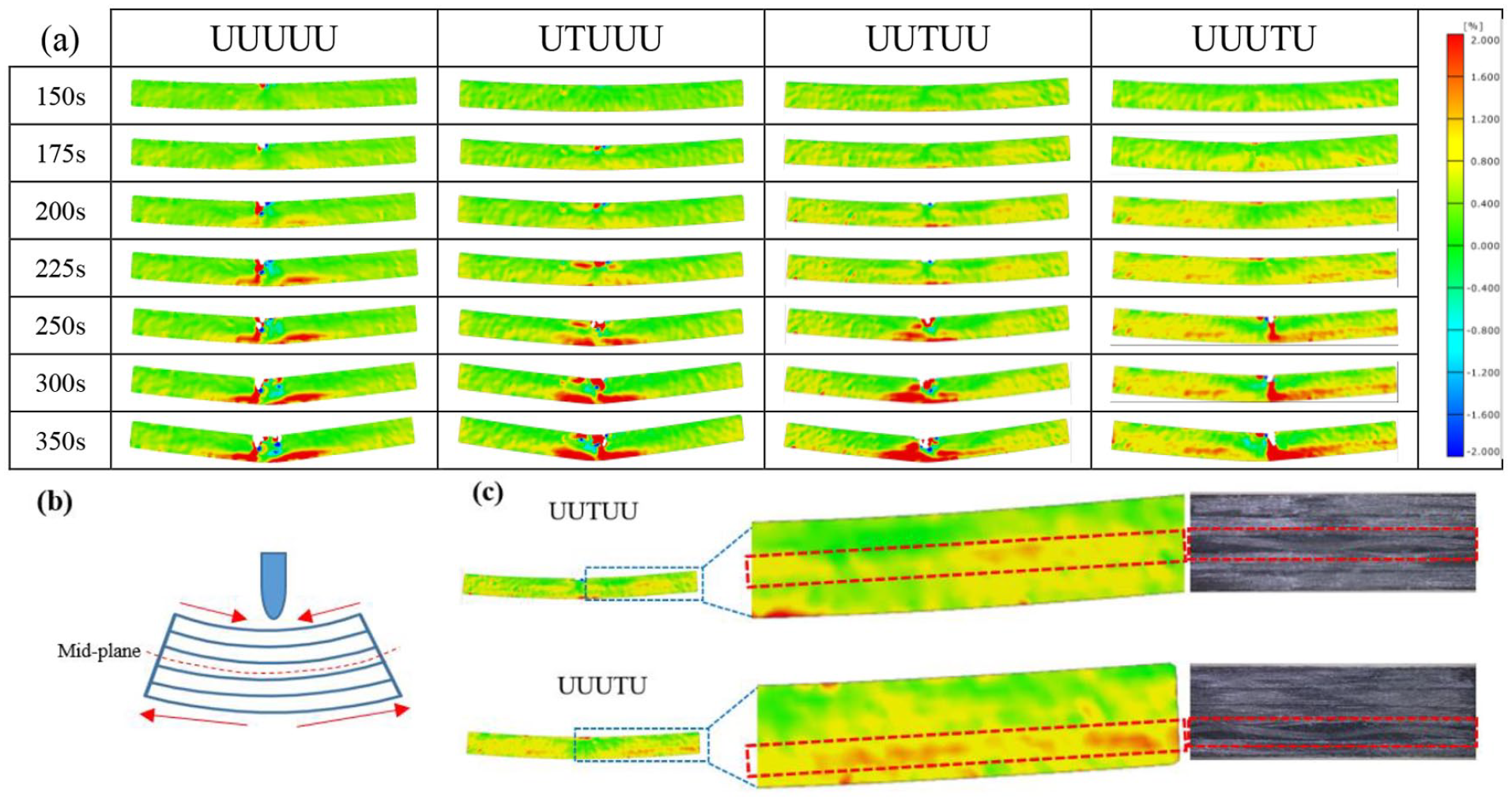
DIC images of samples under bending: (a) DIC images of samples in different time, (b) analysis of different layers under bending force, and (c) DIC images of UUTUU and UUUTU specimens at 200 s and their corresponding stacking sequence.
As shown in Figure 5(b), the fibers above the middle plane are subjected to a compressive force, and the fibers below mid-plane will be subjected to a stretching force when material under the bending force. 21 It can seen from UTUUU that the triaxial woven fabric plays a minor role and it does not receive the force from the indenter by its own change when it has been used for compressed layer. Subsequently, the entire composite is more prone to increase local stress to damage. But in the material in which the triaxial woven fabric is in the middle or tensile layer, the strain of the triaxial woven fabric is obvious as shown in Figure 5(c), indicating that the triaxial woven fabric absorbed energy through its own strain, delaying the destruction of the material. In addition, the overall synergy of materials has been increased. This is also the reason why the flexural strength of UUUTU is the biggest.
From the results of the equivalent flexural strength, it can be observed that when the triaxial woven fabric was used as the stretched layer, the contribution to the property of the material was pronounced. But in the case of the compressed layer, the triaxial woven fabric plays a minor role. That is to say, the triaxial woven fabric can effectively distribute the load when subjected to the stretching force during the bending process, thereby improving the flexural property of the material.
AE test
The DIC detection can reflect the overall strain for the side surface of sample. For the AE signals, it can collect all the signals when samples were broken, including the central region of the specimen. In order to clarify the reasons for the different shapes of these curves, we used acoustic emission instruments to monitor the flexural failure process of these structural composites. Combining the AE amplitude-time and flexural load-time diagrams in the Figure 6, it can be found that the signals acquired by the acoustic emission are consistent with the response of the samples during the bending process. The amplitude point becomes denser and the amplitude increases when the curve of flexural load fluctuates significantly.

Corresponding acoustic emission signal diagram (amplitude) during bending of different specimens. The blue dots represent the “matrix cracking”; the orange dots represent the “fiber/matrix debonding”; the green dots represent the “delamination”; the purple dots represent the “fibers breaking”: (a) UUUUU, (b) UTUUU, (c) UUTUU, and (d) UUUTU.
The bending load of all materials begins to increase linearly while the period of time for this trend in UUTUU and UUUTU are more persistent, especially when the triaxial woven fabric is used as the stretched layer in composites. The reason is that the triaxial woven fabric plays a role in delaying the time at which the composite begins to break. Correspondingly, the values and quantities of amplitude signals are low and less. The load of UTUUU fluctuates obviously near the highest point and lasts for a long time, also, the values and quantities of amplitude signals are both increased. However, the values and quantities for amplitude of UUTUU decrease significantly after the load has fallen from the maximum, and the times of decreasing are longer than UUUUU whose shape of load curve is similar to UUTUU. The reason is that the triaxial woven fabric in UUTUU acts as a resistance after the load drops rapidly, which is why its curve of load maintains an upward trend after a rapid decline and there shown a pit shape in amplitude at this stage. Interestingly, the quantities of amplitude for UUUTU are insignificant in the early stage, indicating that the triaxial woven fabric plays an important role in suppressing damage and resulting in less damage in the early stage of the material, mainly concentrated in the later stage.
In order to reflect the magnitude of the energy generated more intuitively in the time axis, the integral of the energy curves which are the area enclosed by the curve and the time axis were calculated as shown in Figure 7. The values for integral of energy about four kinds of materials do not change much in the beginning and the flexural load at this stage of the material increases linearly with time, resulting in little damage in composites. Nevertheless, the energy in the vicinity of the highest point of the flexural load shows different forms. UUUUU and UUTUU have larger values of histograms, but the duration is very short. Histograms of UTUUU are sparse in this time and last longer. Overall, the area of energy for UTUUU is more evenly distributed on the time axis since 150 s, indicating that the destruction of the composite is continuous and small. This can also be seen from the curve about cumulative integral of energy, because the increasing rate of curve does not change much. Compared with UUUUU, UUTUU has a significantly smaller integral value of energy after passing the highest point of the flexural load, and evenly continues to about the time of 400 s. From the cumulative integral curve of energy, it can be seen that the slope of UUTUU between 225 and 400 s is significantly smaller and stable, then increases significantly after 400 s. The integral value of energy for UUUTU has a large change around the maximum value of the flexural load, but the overall energy is mainly concentrated in the after 250 s. The value of the histogram in the later stage is large and dense, and the cumulative integral curve of energy is also increased during this period.

The integral of the energy to the X axis for different structural composites (the red histogram is the area of the energy curve with the X-axis siege, the black dotted line is the cumulative calculation of the red histogram): (a) UUUUU, (b) UTUUU, (c) UUTUU, and (d) UUUTU.
Damage modes
Generally, it will have several damage modes which contain matrix cracking, fiber-matrix debonding, delamination, and fibers breaking in composites when applying force to the laminates.22,23 In order to explore the role and mechanism of triaxial woven fabrics did in structural composites, we need to decompose the fracture forms of the materials during the bending process. Principal component analysis (PCA) and K-means cluster analysis were carried out by analyzing the amplitude, peak frequency, rise time, and ringing counts collected during the bending process of the material. Meanwhile, the forms of damage were observed during the bending process at different stages and we found that there are four kinds of damage that contain matrix cracking, fiber-matrix debonding, delamination, and fibers breaking in the composites. Besides, the DIC images were helpful to determine the damages modes according to the same testing time. The corresponding parameters for each mode are shown in the Table 1 and each damage mode can be marked during bending process by using these parameters as shown in Figure 6.
Corresponding value of acoustic parameters to various damage modes.

The events of different kinds of damages from the overall damage of composites were extracted and distributed on the time axis in order to compare the different kinds of damages between different materials more intuitively. It can be clearly seen from Supplemental Figures S4–S7 that the composites with triaxial woven fabric, the matrix cracking, fiber-matrix debonding signals of the composites are increased, and the delamination and fibers breaking signals are significantly reduced, especially the delamination signals. The reason is that there exist hexagonal holes which formed a plurality of hexagonal resin blocks similar to the time funnel in the triaxial woven fabric as shown in Figure 8(a). It is worth to mention that the buckling of the yarn was not considered on the middle groove of the resin block in here. These resin blocks are uniformly and densely arranged around fibers in the triaxial woven fabric so that the two kinds of damages such as matrix cracking and fiber-matrix debonding during the bending process are observably increased.

The analysis of resin block in triaxial woven fabric of composites: (a) schematic diagram of resin block in triaxial woven fabric, (b) combination of resin block and yarn in triaxial woven fabric, and (c) illustration of cross section at PP1 and corresponding surface of resin block.
The reason why the resin block in the triaxial woven fabric hole was identified as the time funnel is that the cross section of the carbon fiber yarn in the triaxial woven fabric is eye-shaped, so the combination of the resin and the yarn can be shown as Figure 8(b). The resin blocks were densely embedded in the triaxial woven fabric like rivets and joined the two layers of fabric adjacent to the triaxial woven fabric.
The delamination damage of composites generally consists of the shear failure between the fibers with the matrix, and the shear failure of the matrix itself. Nevertheless, the shear strength of the resin matrix is much greater than its strength with the fiber. 24 In order to further investigate the effect of the triaxial woven fabric on the failure modes, it is necessary to obtain the value of the resin blocks in the triaxial woven fabric. As shown in Figure 8(c), the material was divided by the red line PP1 and the cross section in this position was analyzed. According to the structural model of the triaxial woven fabric, 25 the cross section of yarn consists of two arcs with the radius R and the angle 2β (0° < β < 90°). The height and width of the yarn are a and b respectively. θ is the angle between warp yarn and weft yarn and h1 is the buckling wave height of the warp yarns. The upper surface of the resin block is A1B1C1D1E1F1 and the area is denoted by S1. The intermediate plane is A2B2C2D2E2F2 and the area is denoted by S2. The distance between D2 and E2, C2 and D2 can be expressed by b and θ.

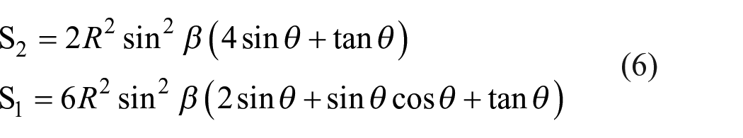
So S2 can be given by

Where the size of S2 is equal to the value for area of the hole in the triaxial woven fabric. And the distance between c and C1 is related to the width of cross section of yarn at this position.

Correspondingly, the distance between D1 and E1, C1 and D1 can be represented as

So S1 can be given by

However, the relationships between b, c, β, θ can be calculated as

The values of S1 and S2 can be further calculated as
Therefore, the values of S1 and S2 are related to the R, β, and θ. We can combine them with the porosity in the structural model of triaxial woven fabric composite in order to calculate conveniently. Because the area of the median plane of the resin block in this paper is equal to the area of the hole in the triaxial woven fabric composite. And the porosity of triaxial woven fabric composite 25 was represented by

So in the triaxial woven fabric reinforced unidirectional fabric composite, the area ratio ρ of upper surface of the resin block can be defined as

It is found that the riveting area ratio is a fixed value. Besides, the area ratio of the resin blocks in the triaxial woven fabric layer is up to three-quarters and the resin blocks are evenly nested in the triaxial woven fabric, which makes the delamination damage not easy to occur. Also, it is the reason that the reduction of delamination signals after adding the triaxial woven fabric in composites.
In addition, the bending process of the composites can be divided into three stages in time as shown in Supplemental Figure S4–S7. The first phase (I) refers to the early stage of bending, and the bending load increases linearly. Only the matrix cracking and fiber-matrix debonding have occurred at this stage. The period of time is defined as the second phase (II) that from the end of the first phase until the flexural load has fallen through the highest point. There is a significant change in the number of events for delamination and fiber breaking at this stage. The third phase (III) refers to the drop from the maximum flexural load to the end of the experiment.
In the first phase (I), the deflection of the composites is small, the load is linearly increased. However, UUTUU and UUUTU have fewer events of matrix cracking and fiber-matrix debonding during this stage. This shows that when the triaxial woven fabric is in the compressed layer of the composites, the contribution it made is not obvious, but when it is in the stretched layer, the triaxial woven fabric can takes part of the pressure from the indenter and slows down the tendency of the material to produce excessive local strain.
In the second phase (II), as the deflection increases, the load of the material no longer increases linearly, but close to the highest point after the wave rises. In addition to the increase in the signal of matrix cracking and fiber-matrix debonding, the events of delamination and fibers breaking have been displayed at this phase. UUTUU lasts for the longest period of time at this stage, besides, the curve of flexural load is showing a “saw tooth” shape. The reason is that the triaxial woven fabric is subjected to compressive force during bending in UTUUU, while the fiber has a compressive strength much smaller than the tensile strength so that the delamination and fibers breaking are mainly concentrated in the upper layer. The triaxial woven fabric which is slowly broken along with the first unidirectional fabric before it plays a significant role as shown in Figure 9(a) and that is why there exist the intermittent damages near the maximum flexural load. UTUUU has a significant increase in delamination and fibers breaking, except for matrix cracking and fiber-matrix debonding. In addition, the events of delamination and fibers breaking correspond to the flexural load and present a long and intermittent state. The triaxial woven fabric layer in the UUTUU can obtain more strain with the increase of the deflection. It contributes to the whole structure and absorbs a part of the energy. Fibers in the triaxial woven fabric and unidirectional fabrics were destroyed more concentrated, unlike the intermittent destruction in UTUUU. Furthermore, the triaxial woven fabric is in the stretched layer in UUUTU, which can generate more strain and can more effectively disperse the force from the indenter, thereby improving the overall flexural performance of the material.
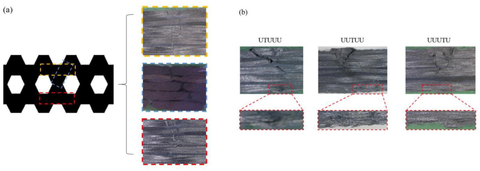
Micrographs from the damages of composites: (a) microscope images of UTUUU at different positions along the triaxial woven fabric in the second phase (II). The first layer of unidirectional fabric and triaxial woven fabric showed obvious damage, and (b) microscopic images of different structural composites in the third phase (III) that delamination and fibers breaking occurred at the bottom in composites.
In the third phase (III), as the deflection increases, the strain of the fibers in stretched layer further increased and began to break. The fiber breakage and material delamination at this stage both occurred in the compressed and stretched layers as shown in Figure 9(b).
Interestingly, the curve of flexural load for UUTUU has an increasing tendency after the maximum value of the flexural load and there are few signals of delamination and fibers breaking at this period. It shows that the triaxial woven fabric plays an important role for composites after the destruction of the upper fibers. Moreover, the signal of delamination and fibers breaking for UUUTU shows a significant trend of increase in the third phase. It shows that the triaxial woven fabric plays a more important role in UUUTU, and the fibers in triaxial woven fabric and unidirectional fabric are destroyed more concentrated in this period.
Conclusions
By changing the sequence of the triaxial woven fabric in unidirectional fabrics, the composites were prepared by the method of controlling the thickness for bending test. At the same time, the flexural strength was calculated to exclude the influence of the width, thickness of the sample on the bending performance. The influence of the fiber volume fraction on the flexural performance was further eliminated by calculating the equivalent flexural strength. The order was arranged as UUUTU > UUTUU > UTUUU ≈ UUUUU. And it can be found that the triaxial woven fabric played a significant role in composites when it was used as stretched layer. The outcomes of DIC show that the effect of the triaxial woven fabric was obvious in UUUTU.
According to the acoustic signals that collected in real time, the mechanisms of damages for different structural composites were analyzed. Corresponding to the amplitude signals, the energy signals, and the flexural load, the contribution of the triaxial woven fabric in composites for bending properties due to the different structural composites was further discussed. When the triaxial woven fabric was used as stretched layer, it played an important role in delaying the time at which the composite begins to break and in suppressing damage in the early stage of composites, concentrated in the later stage. The energy curve shows that the triaxial woven fabric can slow down the damage of composites, especially after the material has passed the maximum load.
Furthermore, the acoustic signals were classified by four classes, and the different kinds of signals were corresponding to the failure modes through observation. The signals of matrix cracking and fiber-matrix debonding decreased and the signals of delamination and fibers breaking increased after addition of the triaxial woven fabric, and the riveting area of the resin blocks were calculated after establishing the model. Finally, different kinds of signals were distributed on the time axis respectively and the bending process was divided into three phase on time axis according to the damage modes. The contribution of delaying damages is not obvious when triaxial woven fabric was used as the compressed layer of the composites, but when it was used as the stretched layer, the triaxial woven fabric can takes part of the pressure from the indenter and slows down the tendency of the material to produce excessive local strain.
Supplemental Material
sj-pdf-1-jef-10.1177_15589250211032324 – Supplemental material for Flexural behavior analysis of composites with triaxial woven fabric as reinforcement
Supplemental material, sj-pdf-1-jef-10.1177_15589250211032324 for Flexural behavior analysis of composites with triaxial woven fabric as reinforcement by Yunfei Rao, Chen Zhang, Zhe Li, Qianqian Li, Honghua Zhang and Wei Li in Journal of Engineered Fibers and Fabrics
Supplemental Material
sj-pdf-2-jef-10.1177_15589250211032324 – Supplemental material for Flexural behavior analysis of composites with triaxial woven fabric as reinforcement
Supplemental material, sj-pdf-2-jef-10.1177_15589250211032324 for Flexural behavior analysis of composites with triaxial woven fabric as reinforcement by Yunfei Rao, Chen Zhang, Zhe Li, Qianqian Li, Honghua Zhang and Wei Li in Journal of Engineered Fibers and Fabrics
Footnotes
Author’’s Note:
All authors is now affiliated to Center for Civil Aviation Composites, Donghua University, Shanghai, China.
Declaration of conflicting interests
The author(s) declared no potential conflicts of interest with respect to the research, authorship, and/or publication of this article.
Funding
The author(s) disclosed receipt of the following financial support for the research, authorship, and/or publication of this article: This work was partially supported by the Fundamental Research Funds for the Central Universities and Graduae Student Innovation Fund of Donghua University. Grant No. CUSF-DH-D-2019052.
Supplemental material
Supplemental material for this article is available online.
References
Supplementary Material
Please find the following supplemental material available below.
For Open Access articles published under a Creative Commons License, all supplemental material carries the same license as the article it is associated with.
For non-Open Access articles published, all supplemental material carries a non-exclusive license, and permission requests for re-use of supplemental material or any part of supplemental material shall be sent directly to the copyright owner as specified in the copyright notice associated with the article.