
Abstract
In this paper, the off-axis tensile behaviors of triaxial woven fabric reinforced rubber composites (TWFR) was studied experimentally and numerically. The tensile failure morphologies and stress-strain curves of specimens cut at seven different off-axis angles (0°, 15°, 30°, 45°, 60°, 75°, and 90°) were obtained by finite element analysis and experiment. The finite element analysis results were found to be in good agreement with the experimental results. Stress-strain curves indicated the TWFR exhibited nonlinear tensile behavior under off-axial tension loading, and could be divided into the coupling working stage of yarns and rubber matrix in TWFR, and the stressed stage of yarns. Similar tensile properties were observed for specimens cut along the direction of angle bisector of any two sets of adjacent yarns. The tensile failure morphologies indicated that the failure mechanism of TWFR was tensile-shear mixed failure.
Introduction
Triaxial woven fabric (TWF) is made up of three groups of yarns interlacing at a certain angle (usually 60°) in a plane, as shown in Figure 1. Due to TWF’ quasi-isotropic mechanical properties, good structural stability, high tear strength, and bursting resistance, triaxial woven fabric resin matrix composites has drawn great research interest in recent years.1–3 However, current research on triaxial woven fabric resin matrix composites mainly focus on the mechanical properties of TWF-reinforced rigid composites, TWF-reinforced flexible composites are rarely reported. 4 Yet, TWF is also advantageous to be used as flexible composite reinforcements for highly isotropic requirements, such as rubber diaphragms. Zhou et al. studied the bursting performance and Trapezoidal tearing performance of TWFR by finite element method and experimental approach. The results showed that TWF and TWFR had more isotropic responses to both bursting and shear deformations compared with conventional woven fabric reinforced flexible composites.5–7 Therefore, it is also necessary to study the anisotropic properties of TWF-reinforced flexible composites.

Triaxial woven fabric.
At present, researchers generally use off-axis tensile performance to characterize the anisotropic properties of materials. The off-axis mechanical properties of materials have been studied through experimental, theoretical analyzing, and finite element simulation methods. Niwa et al. 8 studied the anisotropic tensile properties of plain weave fabrics experimentally and found that plain weave fabrics exhibited substantially lower tensile strength in the direction of angle bisector of yarns than along the yarn axis direction. Junhao et al. 9 investigated the effects of off-axis loading angles and rates on the tensile properties of coated fabrics and analyzed the failure modes. They found that the mechanical properties of coated fabrics were strongly related with loading rates and yarn orientations. The failure of coated fabrics was caused by interface failure, yarn breakage, and composite failure. Zhang 10 studied the tensile properties of two polyvinylidene fluoride coated polyesters under off-axis loading angles and rates and found that the tensile behaviors of polyvinylidene fluoride coated polyester are anisotropic. Wang 11 studied the anisotropic tensile properties of the woven fabric-reinforced lightweight conveyor belt by experimental and analytical methods and discussed the tensile fracture mechanism and applicable strength criteria. Yingying et al. 12 investigated the effects of yarn orientation angles, loading rates, and specimen width on off-axis tensile behaviors of polyvinyl chloride membrane and polytetrafluoroethylene membrane experimentally and analytically. Zhao et al. 13 examined the off-axis tensile mechanical properties and failure behavior of glass plain-weave fabric composites experimentally and compared the results with that obtained from the orthotropic linear elasticity theory and Tsai-Hill failure criterion. It was shown that both off-axis elastic modulus and strength degraded with increasing off-axis angle. The axial modulus obtained from the experimental results was in good agreement with that obtained from the orthotropic linear elasticity theory. Zouari et al. 14 studied woven fabric anisotropy by both off-axis tensile tests and hyper-elastic modeling. Results showed that woven fabric anisotropy depended on weave fabric structure and the loading direction. The orthotropic hyper-elastic model better characterized woven fabric anisotropic tensile property than the orthotropic linear elastic model. Chen 15 experimentally and analytically investigated the anisotropic tensile behavior of off-axis loaded panama tissue and plain weave fabric architectural membrane materials and proposed the failure mechanism and failure criteria. Yi et al. 16 studied the off-axis tensile properties of Polyether sulfone/polyvinyl chloride (PES/PVC) membrane materials and discussed the failure mechanism and applicable strength criteria. Lanlan et al. 17 developed a simple and effective damage constitutive model for PVC-coated fabrics to predict the nonlinear mechanical response of membrane structures under tension. The results of the model agreed well with computation and experimental results. Wang et al. 18 established a mesoscale finite element model to analyze the progressive failure behavior of twill fabric reinforced composites under off-axis tension and compression. The numerical prediction results based on the Murakami-Ohno damage theory coincided well with the experimental results. Xinghai et al. 19 investigated the off-axis tensile mechanical properties of the composite sheet for wood-based winding pipes through numerical fitting, theoretical analysis, and experimental methods. Research showed that both numerical fitting and theoretical analysis can accurately predict the tensile mechanical properties of composite strips for wood-based winding pipes. Li 20 established a non-linear constitutive model to predict the off-axis nonlinear tensile behavior of twisted plant fiber reinforced composites fused with hierarchical angles. Research showed that the prediction accuracy of the constitutive model increased with increasing off-axis angle.
In the present work, finite element analysis and experimental method were used to study the off-axis tensile behaviors and failure mechanism of triaxial woven fabric reinforced rubber composites (TWFR).
Experimental details
Materials
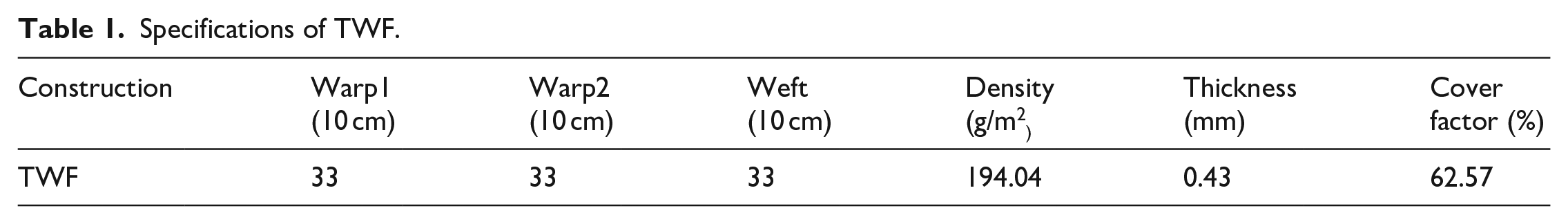
The TWF used in this study were woven with polyamide-66 filament yarns specifications as shown in table 1. The properties of the polyamide-66 filament yarns are as follows 6 : yarn number (186.67 tex), twists (70 T/m), breaking strength (530 MPa), breaking strain (16.12%), and Young’s modulus (5980 MPa). Table 1 shows the specifications of TWF. The weight of TWFR is 3431 g/m2. The fiber mass fraction in the TWFR is 5.8%.
Specifications of TWF.
Tensile test
The off-axis tensile test was conducted according to the HG/T 2580-2008 (professional standard of China) using a 3385H universal testing machine at a constant cross-head rate of 100 mm/min for all specimens. 21 The loading directions were oriented at 0°, 15°, 30°, 45°, 60°, 75°, and 90° with respect to the direction of weft yarns as shown in Figure 2. The specimens were cut into dumbbell shape with dimensions of 150 mm × 50 mm × 2.6 mm as displayed in Figure 3. Specimens were named according to Figure 4.

Orientation of the specimens cut from the composite.

Geometry and dimension of off-axis specimens.

Naming of off-axis tensile specimens.
Finite element model
In this study, the commercial Finite Element Package of ABAQUS/Explicit version 6.14 was employed to predict the off-axis tensile behaviors of TWFR. The computing hardware environment is DDR4 2666 32G memory, Intel i7 6700K Core quad-core 8-thread processor, 64-bit Windows operating system platform.
Geometric model
The finite element models were developed by Solidworks® 20155 based on the yarn cross-sectional shape and yarn trajectory in TWFR, as shown in Figure 5.

The geometrical models of: (a) TWF and (b) TWFR.
Materials properties
The polyamide-66 filament yarn was considered as continuous solid. The yarn was assumed to be transverse isotropic material. The local coordinate system of the yarn is shown in Figure 6.

The coordinate system of the yarn.
The linear elasticity of the orthotropic polyamide-66 filament yarn is defined by giving the “engineering constants”: the three moduli (E1, E2, E3), shear moduli (G12, G13, G23), and Poisson’s ratios (V12, V13, V23) associated with the material’s principal directions. These moduli define the elastic compliance according to formula (1).

Where νij represents the transverse strain in the j-direction when the material is stressed in the i-direction, νij ≠ νji, and νij/Ei = νji/Ej. The 1–2 plane was assumed to be isotropic plane, so E1 = E2 = Ep, ν31 = ν32 = νtp, ν13 = ν23 = νpt, G13 = G23 = Gt, with p and t denoting “in-plane” and “transverse” respectively, νtp characterizing the strain in the plane of isotropy, νpt characterizing the transverse strain in the direction normal to the plane of isotropy, νtp/Et = νpt/Ep, and νtp ≠ νpt.
In this way, formula (1) is reduced to formula (2).
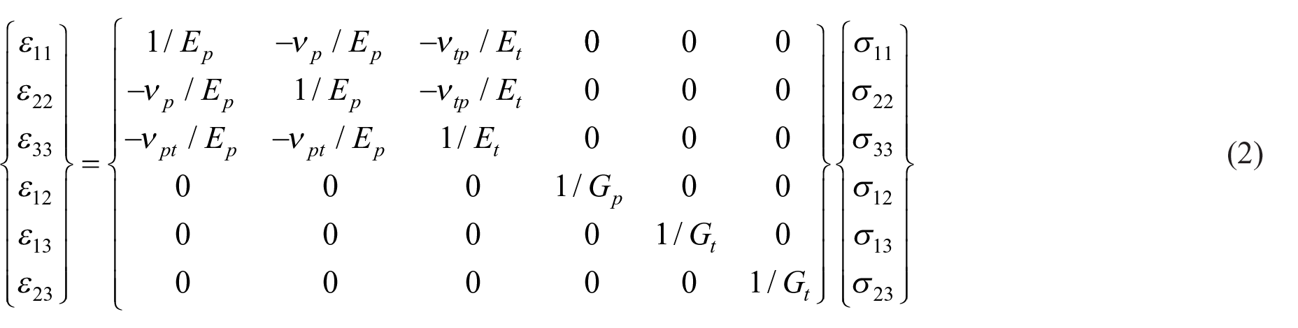
where Gp = Ep/2(1 + vp).
In the transversely isotropic case, Ep, Et, Gp, Gt, vp satisfies formula (3)–(7):

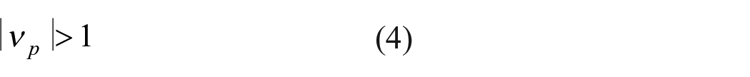


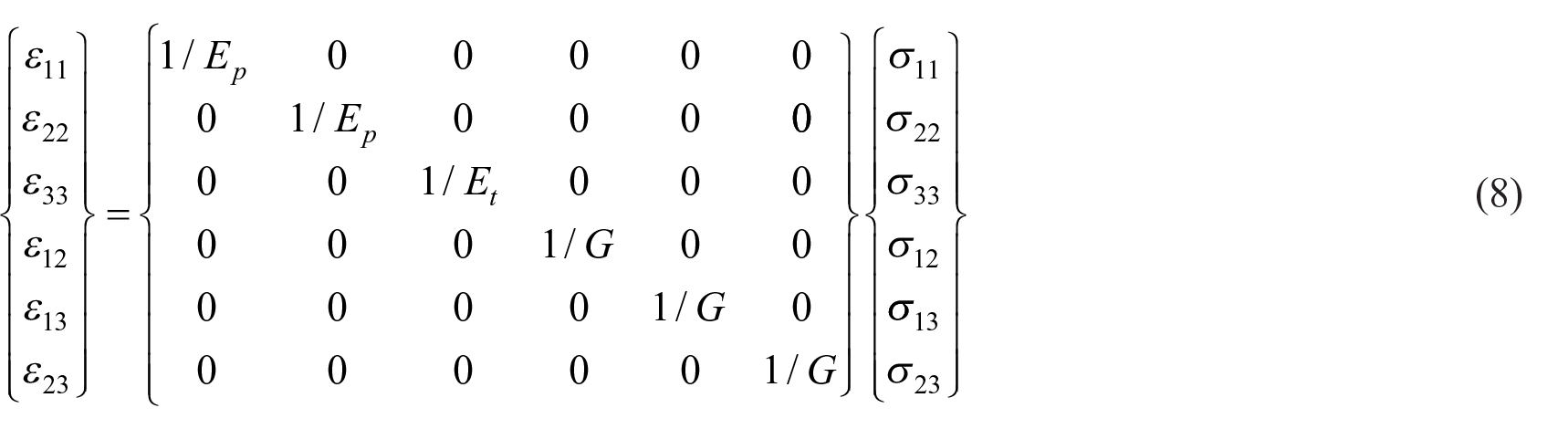
Literature shows that the shear modulus Gp and Poisson’s ratio νp are very small,22,23 and the transverse elastic modulus Ep is very small compared with the longitudinal elastic modulus Et, with Ep is about 0.01–0.001 times of Et. Here, the transversely isotropic material parameters of the yarn are further simplified. The Poisson’s ratio in each direction of the yarn is 0 and the shear modulus of the yarn in each direction is equal (Gp = Gt = G). The parameters of the Polyamide-66 filament yarn are shown in Table 2. Formula (2) is simplified to formula (8):
The material parameters of the Polyamide-66 filament yarn.

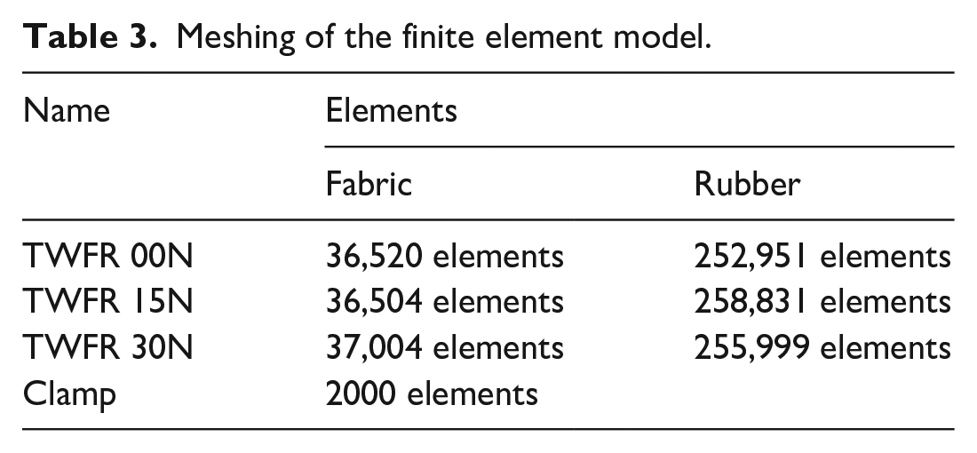
Meshing of the finite element model.
Formula (9) satisfies the relationship:

The failure process of TWF mainly depends on the tensile properties of the yarns along the axial direction. Thus, the axial tensile failure of the yarns is necessary to be determined. In the present work, the ultimate failure strain of the yarns was adopted to control the failure of TWF. The axial tensile strain of the yarn was obtained by experimental testing as ε33max = 16.12%. When ε33 > ε33max, the unit was considered to have failed. The failure criterion was realized through ABAQUS subroutine “VUSDFLD.” The property of the clamps was defined as follows: Young’s modulus (2.10 × 10⁵ MPa), density (7.8 g/cm3), and Poisson’s ratio (0.3). The Rubber matrix was assumed as isotropic with modulus of 100 MPa, yield stress of 20 MPa, peak stress of 30 MPa, and plastic strain of 100%.
Finite element parameter setting
In the off-axis tensile testing process, clamps held specimens tightly and moved upward. Therefore, in finite element modeling, the clamps at both ends were regarded as rigid bodies and referred as RP-1 and RP-2 reference points respectively. Boundary conditions and loads were accordingly applied on the two reference points as shown in Figure 7. In the finite element analysis model, the tensile load was the reaction force of RP-1 and RP-2 in the X direction. Therefore, the reaction force of RP-1 and RP-2 in the X direction and the displacement with time were the main output parameters.

Load and boundary conditions applied on the finite element model.
In the tensile testing process, the specimens were griped tightly by clamps to avoid slippage. Therefore, the “ALL WITH SELF” universal contact algorithm was used to define the interaction between yarns (the friction coefficient was 0.05). “Tie” connection was used to define the interaction between the clamps and specimens, yarns, and rubber matrix. In the finite element model, the high-quality meshing guarantees the accuracy of calculation results. However, the size of the mesh affects the computation speed in ABAQUS/Explicit. Considering of the mesh quality and computation speed synthetically, the linear reduction integral hexahedral solid element (C3D8R) was selected. Meshing in finite element model of specimens as shown in table3
Results and discussions
Tensile stress-strain curves
Figure 8(a) and (b) show tensile stress-strain curves of TWFR loaded at various off-axis angles obtained from both experiments and finite element simulations. The tensile property data are summarized in Table 4. It can be seen that the finite element simulation results agreed well the experimental results, which verified the feasibility and accuracy of the finite element model and chosen material failure criteria. The stress-strain response of TWFR was nonlinear and could be divided into two stages: coupling working stage of yarns and rubber matrix in TWFR and the stressed stage of yarns. In the yarns and rubber matrix cooperative working stage, linear behavior was observed with tensile stress increasing linearly in the initial small strain range. In the stressed stage of yarns, nonlinear behavior was observed with tensile stress increasing nonlinearly until ultimate failure appeared. This may be attributed to the domination of yarns on the tensile behavior of TWFR during the off-axis tensile test and the fact that the failure of the yarns was governed by the interlocking characteristics of the three groups of yarns in TWF and the consolidation effect of the rubber matrix. As the rubber matrix deformed with increased load, the clamped yarns started to get straightened and non-clamped yarns become buckled, which resulted in a decrease in the slope of the stress-strain curves of TWFR. This was then followed by the breakage of the yarns, which led to the failure of TWFR and the maximum ultimate failure stress.
Tensile property summarized from the finite element analysis and experimental results.

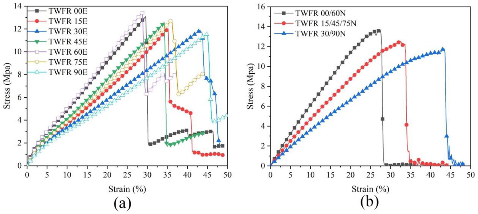
Stress-strain curves of off-axis loaded TWFR obtained from experiments (a) and FEA simulations (b).
Figure 8(a) and (b), and Table 4 also show that tensile properties of specimens cut along the direction of the angle bisector of any two sets of adjacent yarns were similar. Similar elastic modulus, failure stress, and failure strain was observed for 0° and 60° specimens, 15°, 45°, and 75° specimens, and 30° and 90° specimens, respectively. Moreover, as the loading angles changed from on-axis directions to off-axis directions, decrease in failure stress and elastic modulus, and increase in failure strain was observed. Particularly, the failure stress and elastic modulus of 0° and 60° specimens >15°, 45°, and 75°specimens >30° and 90° specimens, while the failure strain of 0° and 60° specimens <15°, 45°, and 75° specimens <30° and 90° specimens. This phenomenon is mainly caused by the distribution of yarns in TWFR, as shown in Figure 9. When TWFR was stretched, the yarns can be divided into clamped and non-clamped yarns. Clamped yarns with both ends held by clamps can withstand greater tension and contribute greatly to the tensile stress in the off-axis directions. Non-clamped yarns with one end or no ends held by clamps can only bear part of the tension and the shearing force come from the rubber matrix and contribute little to the tensile stress. Hence, when the loading direction changed from on-axis to off-axis sequentially, the increasing decrease in the number of yarns held at both ends led to gradually decreased tensile stress. On the contrary, the failure strain of the on-axis specimens only depend on the elongation of the yarns under stretching, and the failure strain of the off-axis specimens consists of both the elongation of the yarns under stretching and the elongation caused by the deflection of the yarns. Although the adhesion of the rubber matrix restricts yarn deflection, the ultra-high elasticity of rubber still enables yarns to deflect to a certain extent. Thus, the specimens showed gradually increased failure strain as the loading direction changed from on-axis to off-axis sequentially.

Yarn distribution of TWFR in off-axis tensile testing: (a) 0°/60°, (b) 15°/45°/75°, and (c) 30°/90°.
Off-axis tensile failure characteristics
Figure 10 shows failure morphologies of TWFR from experiments. As we have mentioned from Figure 9 that specimens consist of both clamped and non-clamped yarns when stretched at any off-axis angles. For specimens with off-axis angles 0° and 60° in Figure 9(a), A yarns were parallel to the testing direction and only bore tensile load, while B and C yarns underwent the combined action of tensile load of the clamps and shearing force of the rubber matrix. B and C yarns deflected and straightened along the direction that reduces the angle with the stretching direction. Although the interlocking characteristics of yarns in TWF prevented the third group of yarns from slipping and the consolidation effect of rubber on yarns prevented B and C yarns from deflecting and straightening, a certain degree of deflection and straightening can still occur to B and C yarns due to the ultra-high elasticity of the rubber matrix. Therefore, during testing, A yarns were firstly stretched to breakage, B and C yarns were then pulled out from the rubber matrix. Failure of specimens correspondingly occurred and expanded along B or C yarn directions, as shown in Figure 10(a). For specimens with off-axis angles 15°, 45°, and 75° in Figure 9(b), under the action of the tensile load of clamps and shearing stress of the rubber matrix, specimens were damaged due to breaking of inclined yarns from the rubber matrix. Damage morphology extended along a certain inclined yarn direction, as shown in Figure 10(b). For specimens with off-axis angles 30°, and 90° in Figure 9(c), A yarns were perpendicular to the testing direction and were only subjected to shearing force of the rubber matrix, contributing little to the tensile stress, while B and C yarns were damaged under the action of tensile load of the clamps and shearing force of the rubber matrix. Corresponding damage morphology is shown in Figure 10(c). In summary, the tensile failure mode of TWFR along various off-axis angles are tensile-shear coupled failure mode.
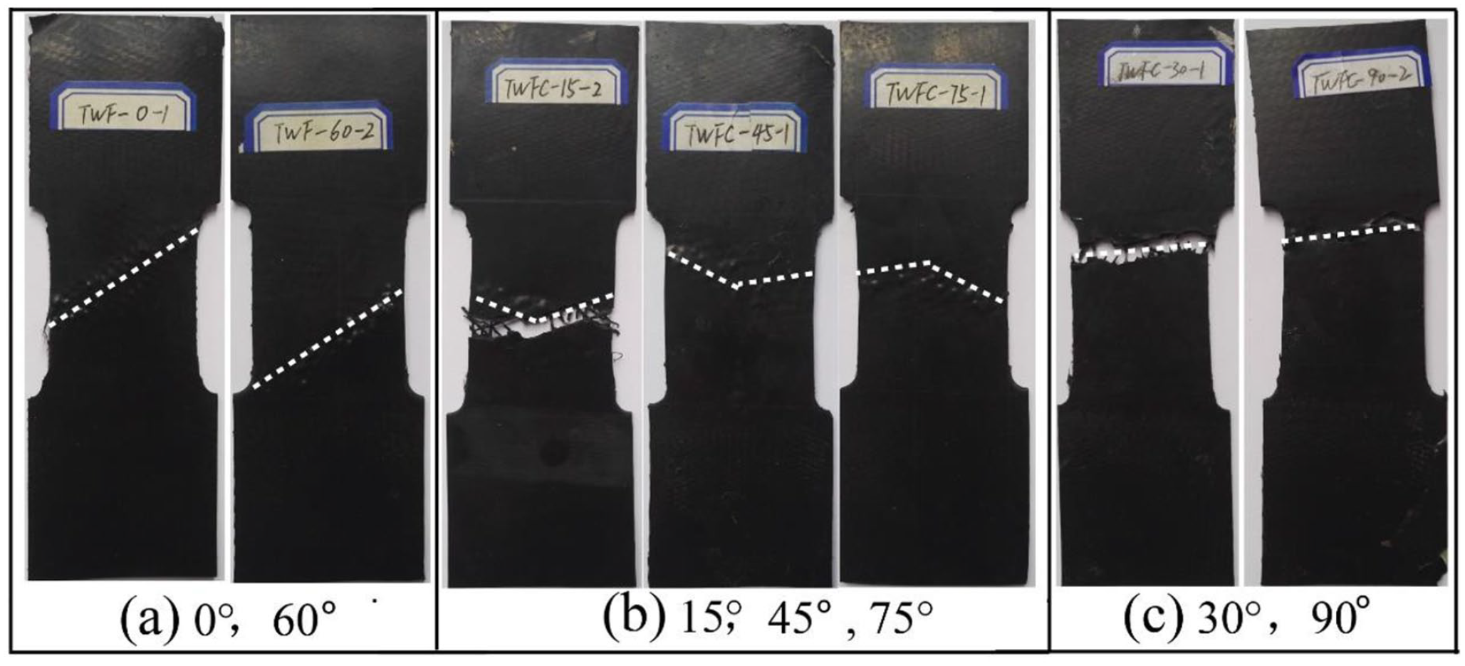
Damage morphologies of TWFR off-axis specimens: (a) 0°/60°, (b) 15°/45°/75°, and (c) 30°/90°.
It can also be seen from Figure 10 that specimens didn’t break after tensile failure but formed a protruding point structure on the surface. This is mainly because of the dominated role of TWF played on the performance of TWFR. The yarns in TWF have high tensile stress and elastic modulus, as well as low failure strain. After the yarns in TWF broke under tensile loading, the tensile testing equipment defaulted to material failure and the upper clamp returned despite the fact that the rubber matrix didn’t fail. However, the broken yarns pulled out from the rubber matrix cannot be restored to the initial status and a convex point was formed at the fracture surface. Figure 11 shows that the yarns had good interfacial bonding with the rubber matrix and were pulled out from the matrix and broke under the action of tensile load.

Damage morphology of yarns in the fractured specimen.
Figures 12 to 14 show the stress distribution of TWFR under off-axis tensile loading obtained by finite element simulation. At off-axis angle 0°, it can be seen from Figure 12 that yarns at the edge of the specimens shrank slightly to the centerline. Yarns were parallel to the testing direction showed the highest strength utilization rate. Yarns near the centerline bore the greatest tensile stress and broke earliest. Yarns at the direction of 60° with respect to the testing direction broke under the combined action of tensile stress and shear stress and showed low strength utilization rate. The stress along the testing direction was contributed by shear stress of the rubber matrix and the axial tensile stress of yarns in the testing direction. At off-axis angle 15°, all yarns in the specimen bore both tensile stress and shear stress of the rubber matrix. Yarns held at both ends bore the greatest tensile stress and broke firstly. Yarns that are not held at both ends mainly bore shear stress of the rubber matrix and tensile stress of the nearby yarns, showing low strength utilization rate. At off-axis angle 30°, yarns at the direction of 60° with respect to the testing direction were subjected to great tensile stress and slight shear stress. Under this coupling action, they broke firstly. The damage of the specimen extended along the group of yarns that were perpendicular to the testing direction as they only bore shear stress of the rubber matrix and prevented the expansion of the damage.

Stress distribution of TWFR specimens under 0°-axial loading.

Stress distribution of TWFR specimens under 15°-axial loading.

Stress distribution of TWFR specimens under 30°-axial loading.
Figure 15 shows the tensile failure results of TWFR at various off-axis angles from finite element simulation. It can be seen that under uniaxial tensile loading, the fracture expansion direction of each off-axis angle specimen was along the yarn direction. This is mainly due to the interlocking effect of the three groups of yarns in TWF which restricted yarn deformation during stretching.

Damage morphologies of TWFR under off-axis tensile loading: (a) 0°, (b) 15°, and (c) 30°.
Conclusions
This work studied the off-axis tensile performance and damage behavior of TWFR by experimental approach and finite element simulation method. The conclusions are as follows:
Under off-axis tensile loading, the stress-strain curves of TWFR changed nonlinearly, and could be divided into the coupling working stage of yarns and rubber matrix in TWFR, and the stressed stage of yarns.
Specimens cut along the direction of the angle bisector of any two sets of adjacent yarns showed similarTensile properties. As the loading angles changed from on-axis directions to off-axis directions sequentially, decrease in failure stress and elastic modulus, but increase in failure strain was observed. The tensile failure mode of TWFR along various off-axis angles were tensile-shear coupled failure mode.
Numerical simulation results of off-axis tensile behaviors of TWFR are in good agreement with experimental test results, which verified the accuracy of the finite element model and related parameter settings.
Footnotes
Declaration of conflicting interests
The author(s) declared no potential conflicts of interest with respect to the research, authorship, and/or publication of this article.
Funding
The financial supports from The Integration Platform of Industry and Education of Jiangsu Higher Vocational Education (grant No. 2019, 26), Scientific Research Fund of Yancheng Polytechnic College (grant No. 2020–01). Qinglan Project of the Jiangsu Higher Education Institutions of China, Jiangsu High Vocational College Academic Leaders High-end Research and Training. The High Education Science Foundation of Jiangsu Province (21KJB540007).