
Abstract
In the present study, a finite element impact model was created and analyzed by commercial FEM code ANSYS®-AUTODYN and then validated by drop weight impact experiment. Moreover, models of single- and multilayer panels of plain weave as well as different weaving architectures were designed and created with and without holes to compare impact properties. The influence of the size and location of hole defect on the impact behavior of single-layer Twaron® fabric were investigated, the degree of influence of hole defects with different sizes on the impact behavior and the influence level by different location of the hole defects were well investigated in. In addition, the effect of hole defects on the impact behavior of multi-layer armor panel were studied. Hole defects were less influential in terms of impact contact force and had less severe constraining effect on front layer of the panel when the number of multi-layer armor panels increased. Furthermore, the effect of hole defects on the impact behavior of different weaving architectures (i.e. plain, twill, basket, and satin weave) were analyzed. Plain weave fabric had the highest energy absorption capability in impact scenarios with and without holes among all the woven architectures. Plain weave fabric was the most affected and twill weave was the least affected by hole defects in terms of transverse wave velocity; the satin weave was the most affected and the twill weave was the least affected by hole defects in terms of energy absorption. These findings will provide guidance for engineering of soft body amour and composite materials.
Introduction
High-performance fibers, which have high strength and high stiffness, including aramids, such as Kevlar® (DuPont) and Twaron® (by Teijin); PBO fibers, such as Zylon® (by Toyobo); and ultra-heavy molecular weight polyethylene (UHMWPE) fibers, such as Dyneema® (by DSM) and Spectra® (by Honeywell), are widely used in ballistic protection owing to their flexibility and high strength-to-weight ratio.1–3 These fibers are essentially elastic in tension and have a very high tensile modulus. Hundreds of high-strength fibers are grouped together to make a yarn, and yarns are woven to produce a ballistic fabric.
Over the past several decades, numerous experiments and theoretical studies have been conducted to understand the impact behavior of these high-performance fabrics.4–8 Analytical methods are one of the approaches used to investigate, analyze, and understand the impact mechanisms of materials. Gu 9 presents an analytical model to calculate decrease of kinetic energy and residual velocity of projectile penetrating targets composed of multi-layered planar Twaron® plain-woven fabrics. In addition, numerical and experimental methods are frequently applied to the studies of ballistic performance of high-strength fabrics. Shockey et al. 10 performed the impact tests of the fragment on fabric targets using gas-gun to examine the influence of Zylon® fabric material, mesh density, boundary conditions and impactor sharpness on the ballistic response. Duan et al. 11 and Ha-Minh et al. 12 studied the ballistic impact behavior of a woven Kevlar KM2® fabric numerically and analyzed on the effect of yarn density. However, it must be noted that most existing impact research on high-performance fabrics for soft body armor was focused on medium to high velocity (30–1000 m/s) low-mass projectiles. In our previous study, 13 a low-velocity drop weight impact experiment setup for high-performance fabrics was designed and the low-velocity impact model was presented, the study filled the gap of data empty of high-performance fabric in low-velocity impact performance. Besides this, research on low-velocity impacts on high-performance fabrics is almost nonexistent. We attribute the reason to following. From an experimental perspective, experiments using impactor with high mass and low velocity, the test sample is always difficult to fix precisely because of the fabric’s flexibility, which results in inaccurate results. From a numerical analysis perspective, the CPU calculation time of low-velocity impacts may be as much as a dozen times longer than that for high-velocity impacts because the low-velocity impactor takes much longer to penetrate the fabric and the time step in the explicit schema is always much lower to ensure the calculation precision. Thus, compared to high-velocity impacts, studying low-velocity impacts on soft body armor is more challenging.
In the existing impact research of high-performance fabrics, various physical, and mechanical properties affect the impact performance of fabrics are discussed, including the woven architecture2,14 and physical properties, such as crimp,15,16 thread and yarn linear density, 17 inter- and projectile-yarn friction coefficient,18–21 fabric boundary conditions,19,22 and projectile shape.23,24 However, little research exists on the influence of fabric defects on the mechanical properties of high-performance fabrics. Defects such as holes often appear in fabrics, which are the main components of soft body armor, after long-term use or damage. Furthermore, fabric reinforced composites containing holes like bolt holes and drilling holes are often used in structural applications. Hole defects create stress or strain concentrations, which will weaken the mechanical properties of fabric-based soft body armor or fabric-reinforced composites. 25 Overall, prediction of effect on the mechanical properties of fabrics caused by hole defects is important for material designers.
In recent years, numerical methods, such as finite element analysis, have been identified as effective techniques for impact investigation.26,27 Commercial packages, such as ANSYS®, ABAQUS®, and LS-DYNA®, have frequently been used to develop projectile-fabric simulation models and analyze the impact performance of these materials. Although numerical methods have high requirements in terms of computing power and resources for simulating the process, there are clear advantages to these methods: they are fairly accurate, inexpensive, easy, and consume no materials. 28 Thus, these methods have become widely used tools for quickly and efficiently exploring new materials, weaves, and architectures through parametric studies and for identifying and understanding various mechanisms of deformation, failure, and energy dissipation that cannot be easily elucidated through experimental means. 29 Hence, we seek to better understand the low-velocity impact behavior of high-performance Twaron® fabric through numerical method as it can provide deeper insight into the nature of impact events.
In summary, at present, it is still crucial for engineering to develop high-performance fabrics with improved all-round impact resistance performance. Therefore, in this study, great challenge was taken to investigating the impact performance and failure mechanism of high-performance fabrics with and without hole defect under low-velocity impacts from different perspectives. First, the influence of the size and location of hole defect on the impact behavior of single-layer Twaron® fabric are investigated. In addition, the effects of hole defects on the impact behavior of multilayer armor panels as well as different weaving architectures (i.e. plain, twill, basket, and satin weave) are analyzed. A huge calculation time is the cost of attempting to make a breakthrough in the study of low-velocity impacts on soft body armor.
Finite element simulation
Constitutive model and parameters
A commercial explicit nonlinear finite element (FE) analysis code, ANSYS®-AUTODYN, is used for FE modeling of low-velocity drop weight impact on the Twaron® CT612 fabric. The fabric model is simulated at the yarn level by SolidWorks®. At the microscopic scale, the yarn level is capable of capturing the behaviors of the fabric upon ballistic impact. 30 An impact model is designed according to the fabric’s geometry parameters and the experimental set-up. The width and height of the yarn cross section and the wavelength were set as 0.902, 0.1, and 1.818 mm, respectively, according to measurements of the real fabric with a Yashima® YDU-3S digital microscope shown in Figure 1(a–c). The cross-sectional area is assumed to be of lenticular shape, which comprises two segments and remains constant along the yarn length. The clamping used in the experimental set-up involved a drop weight impact tester (9250HV, INSTRON®) with the fabric target clamped and centered within a circular test field. Therefore, the circumference of the fabric was fixed, and the fabric model was designed to correspond with a circle having a diameter of 70 mm, which is the same size as the test field. The impactor head was hemispherical with a diameter of 12.7 mm and impact weight of 7.07 kg according to impact equipment. Standard earth gravity was applied to the model for authenticity. Figure 1(d) shows the FE model.

(a) Microscopic cross-section view of fabric, (b) microscopic appearance of fabric, (c) dimensions of the yarn model, and (d) low-velocity impact model.
Twaron® fiber is a kind of poly-aramid fiber like Kevlar and has proved to be viscoelastic and sensitivity to strain rate. 31 A three-element system model reported by Lim et al. 27 was proved effective to provide a reasonable representation of the deformation micro-mechanisms in Twaron fibers. The system contains two Hookean springs and a Newtonian dashpot, which represent elastic, solid, and fluid-like behaviors, and the model can be seen in Figure 2. The stress–stain response of a three-element viscoelastic model can be described by:

where

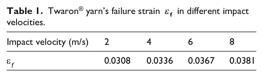
The strain rates can be calculated to be in the range of 9.9–210.7 s−1 when the impact velocity was changed from 1 to 12 m/s. Therefore, by following V.B.C. Tan’s prediction data,
31
the values of Twaron® yarn’s failure strain
Twaron® yarn’s failure strain
Furthermore, the volumetric density of the yarn was 1440 kg/m3, a simple Coulomb friction was introduced between individual yarns and between the impactor and fabric. A friction coefficient of 0.3 was used based on experimental measurements of Twaron® fabrics in our previous study. 32 The friction coefficient of the impactor/yarn was set as 0.2. Mesh sensitivity studies for various element sizes have suggested that it is appropriate that the cross-section of a primary yarn is meshed using 10 elements and 20 elements through the yarn wavelength as shown in Figure 1(c). Simulation result of impact on a straight single yarn indicated that the chosen mesh density was able to capture transverse wave responses of the impact event.

Three-element system model.
Model validation
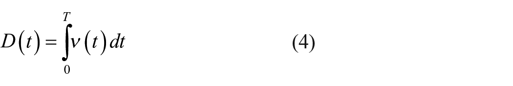
A 9250HV drop weight impact tester provided by INSTRON® was used to validate the model. This is a free-fall drop dart machine with changeable load cells that have a large measurement capacity. The impactor’s height and weight are adjustable to facilitate the different initial impact energies. The test followed to the ASTM D7316 standard. 33 Figure 3(a) shows a schematic of the 9250HV drop weight impact tester. Two sensors for impact loading and acceleration were installed on the impactor with a diameter of 12.7 mm and were used to measure the contact force between the impactor and specimen as well as the acceleration during the low velocity impact. Based on the impact loading F(t), acceleration α(t), and initial velocity vi, calculating the velocity v(t) and deflection D(t) of the impactor and the absorbed energy E(t) of specimen were possible. 34


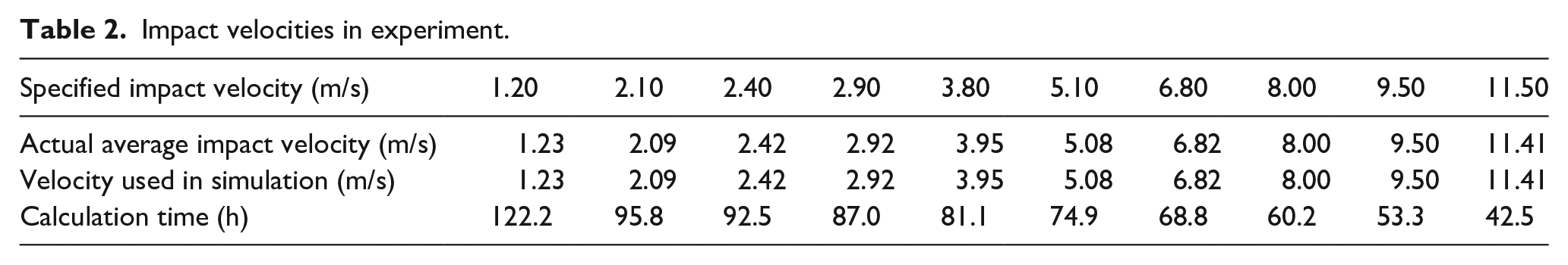
As mentioned in the Introduction, fabrics, unlike hard materials such as steel and composites, are too flexible and cannot be fixed precisely by pneumatic clamp during drop weight impact events. As a result, specially treated specimens were designed. The fabric specimens were first cut to a small size, and then, they were sandwiched between the two treated acrylic plates and bonded with super glue. Detail experimental set-up can be referred to our previous study. 13 Impacts of a single layer of Twaron® CT612 fabric were performed ten times at velocities in the 1–12 m/s range in both experiments and simulations, to avoid random errors and ensure repeatability, at least five specimens were tested repeatedly for each specified impact velocity. The specified experiment impact velocities, actual average impact velocities, velocities used in simulation as well as FEM calculation times( Inter xeon® 12 core CPU) are shown in Table 2. No pull-out phenomenon appeared in the fixed boundary area of the specimens after the experiments, which confirmed the successful design of the specimens. Figure 3(b) shows both sides of the specimen after impact at 8 m/s. Then, the results of fabric’s energy absorption, residual velocities of the projectile as well as F-T curves from the experimental tests and FE simulations were compared. Figure 4(a) and (b) show the correlation between the FE predictions and specimens average experimental results, where the gradients of the regression line are 0.9542 and 1.0015, respectively, which indicates good validity of the model. Besides, the similar F-T curve between experiment and simulation results in Figure 4(c) also verify the validity of the model.
Impact velocities in experiment.

(a) Schematic of the 9250HV drop weight impact tester and (b) both sides of specimen after impact at 8 m/s.
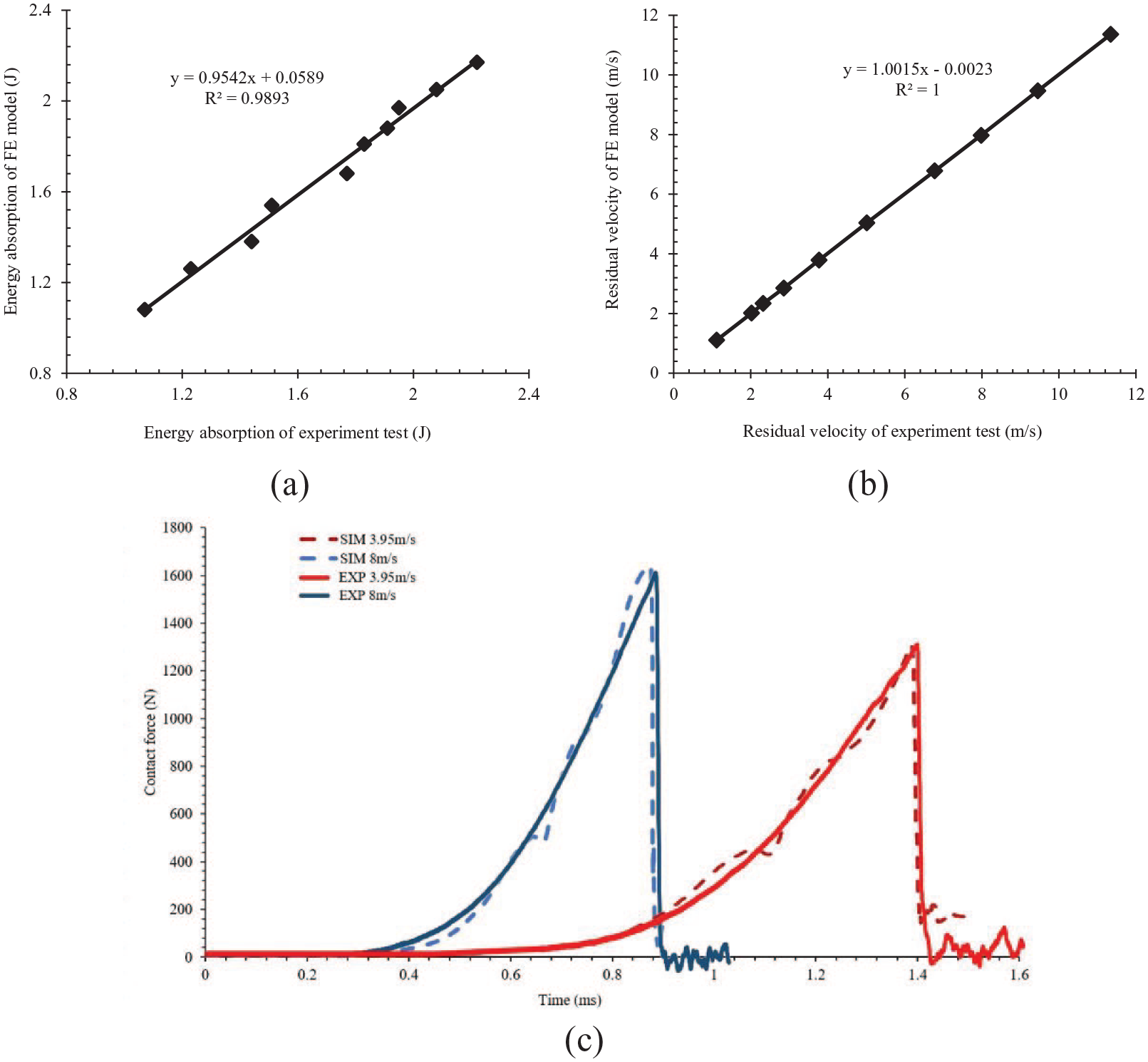
Comparison of FE and experiment results: (a) energy absorption, (b) residual velocities, and (c) F–T curves.
Influence of hole defects on single layer fabric
The process for the drop weight impact experiments in this study was as follows. The impactor was freely dropped from a designated height and its velocity increased to the intended impact velocity as it reached the fabric. At that moment, the fabric deformed and exerted an impact resistance force on the impactor. The impact resistance force increased before eventually reaching a peak when the yarns in the fabric reached their failure stress and started to break. Then, the fabric rapidly reached complete failure. At the moment of failure, the resistance force sharply decreased. Thereafter, only a small amount of frictional force remained, preventing the impactor from reaching its residual velocity and the impact event ended. A hole defect denotes fracture in part of yarns of a fabric, whether will the fracture affects impact resistance ability of a fabric is what this study concerns. Thus, to find out how and to what extent hole defects affect the impact resistance, impact tests of the drop weight impactor at the specimen’s center with an impact velocity of 8 m/s were implemented for all FE impact scenarios. Important indices reflecting the impact resistance ability, such as the maximum contact force during the entire impact event, the impactor’s deflection at the fabric’s time of failure, fabric’s impact duration time before failure, and total energy absorption were determined from FE simulation results. Among these, the total energy absorption includes the loss of projectile kinetic energy and the impactor’s gravitational potential energy. These factors can be calculated from the measured strike and exit velocity of the impactor and the deflection of the impactor at the point of exit using following equation. 13

where ET is the energy absorption by the panel; G is standard earth gravity. M is the mass of the impactor; vi and vr are the strike and exit velocity, respectively; and D is the deflection of the impactor at the time at which the exit velocity is achieved.
Influence of hole defect size
To study the influence of hole defects on the impact behavior of single layer fabric, four different models of Twaron® fabric were created for comparison. The model denoted as P0 has no hole, and models denoted as P1, P3, and P5 are fabrics with hole defects at the sample center with sizes of 1 × 1, 3 × 3, and 5 × 5 yarn interweaving points, respectively; the side length of the holes were, respectively, 7.8%, 23.6%, and 39.4% that of the impactor’s diameter. Figure 5 shows a schematic fabric model of P3. Figure 6 compares the impact results of the different fabric models. Hole defects of greater size had a significantly greater effect on the impact resistance ability of the fabric. The maximum contact force of the fabric P0 without holes was as high as 1635.3 N, but this parameter was reduced to 75.9%, 49.3%, and 19.9% for the impact of fabrics P1, P3, and P5, respectively. Simultaneously, between fabrics P0 and P5, the deflection of the impactor at failure decreased from 6.98 to 6.39 mm and the fabric impact duration time decreased from 0.876 to 0.800 ms. In addition, the energy absorption for P0 was 2.06 J, which decreased to 76.2%, 35.9%, and 11.9% for fabrics P1, P3, and P5, respectively. Larger hole defects involve fracture of more primary yarns (yarns in direct contact with the impactor during the impact process), which play a major role in the impact resistance breakage; hence, the large holes resulted in a sharp decline in the impact resistance performance of the fabric. We conclude that fabric specimens with better impact resistance performance, in other words, greater energy absorption ability, will always have a greater maximum contact force, longer impact duration time, and greater impactor deflection.

Schematic of the P3 fabric model.

Comparison of the impact results of fabrics with different hole defect sizes: (a) maximum contact force and impactor deflection and (b) energy absorption and impact duration time.
Influence of the hole defect location
In addition, we considered the effect of the relative position of the hole and the impact center on the impact performance of the fabric. A unified hole size of 3 × 3 yarn interweaving points was used in all models; each model had a single hole defect at a different location, as shown in Figure 7. The model P3 has a hole at the fabric center, and models H1, H2, and H3 have hole defects arranged in line with the central primary yarn, whereas the models S1, S2, and S3 have the central points of their hole defects arranged equidistantly in a line 45° to the central primary yarn. Due to the round shape of the models, the central points of the hole defects in models H2 and S2 were located at the midpoint between the impact point and fixed boundary.

Schematic of the location of hole defects in each model.
Figure 8 compares the impact results of fabric models with different hole defect locations. Excluding the fabric model P0 without a hole, model S2 had the best impact resistance performance among all the other models. Moreover, model P3 had the poorest performance because the hole defect was located at the model center, which was also the impact point. For models H1, H2, and H3, the impact scenarios resulted in lower energy absorption compared to models S1, S2, and S3, because the hole defects were located in these models’ primary yarns, which contributed the most to energy absorption during impact events. To determine how impact performance changed with distance from the impact center to the center of the hole defect, P3, H1, H2, and H3 were combined into one group and P3, S1, S2, and S3 were combined into another group for further analysis. The energy absorption values of P3, H1, H2, and H3 were, respectively, 35.9%, 49.2%, 73.1%, and 72.5% of the absorption energy of the model P0 without holes; the maximum contact force values were, respectively, 49.3%, 62.0%, 77.5%, and 76.9% that of model P0. The energy absorption values of P3, S1, S2, and S3 were 35.9%, 78.2%, 95.6%, and 94.8% that of model P0, and the maximum contact forces were 49.3%, 79.5%, 99.2%, and 99.0%, respectively. The impact duration time and deflection followed the same trend for both groups. A comparison of the results of the two groups indicates that as the distance between the impact point and the hole defect increased, the midpoint between the impact point and fixed boundary acted as a demarcation point. The energy absorption ability of the fabric first considerably increased and then remained almost stable except for a slight drop. In general, when a fabric with a hole defect is subjected to a drop weight impact, the impact resistance ability is the weakest when the impact point is located at the hole defect. The hole defect of model S2 had the least effect on the impact resistance performance of the fabric. In fact, the influence of the hole defect at the location in model S2 on the impact performance of the fabric was quite limited.
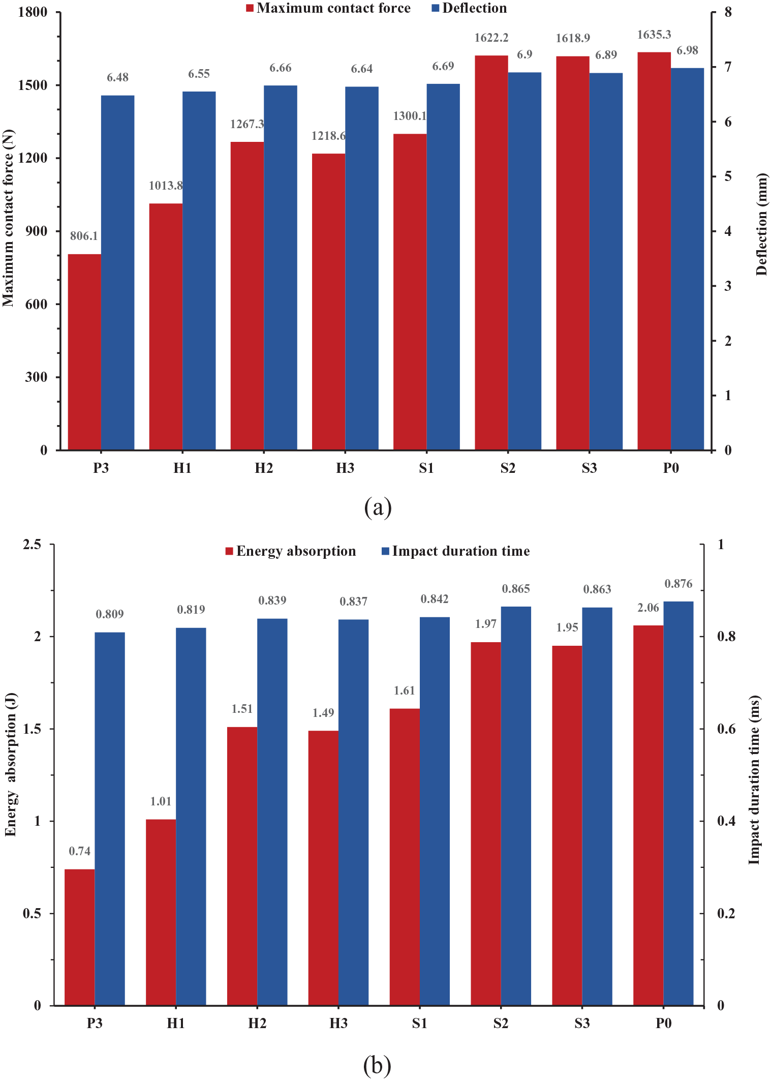
Comparison of impact results of fabrics with different hole defect locations: (a) maximum contact force and impactor deflection and (b) energy absorption and impact duration time before failure.
Influence of hole defects on multi-layer fabric armor panels
High-performance fabrics are frequently assembled into multilayers to improve the energy absorption properties of body armor or composites. In this study, we stacked models of P0 and P3 into 2-, 3-, and 4-layer fabric armor panels for further investigation. Specifications of the specimens are listed in Table 3. The difference in the area density of the panels with and without holes was small; hence, they were considered to be the same.
Specifications of specimens.

Effect on F–t curves
Figure 9 shows the impact comparison results of F–t curves of different stacking layers of P0 and P3. In the impact scenarios without holes, except for a slight fluctuation caused by the stress wave, the contact force in each type of panel basically steadily increased before its peak and then sharply decreased over a very short time after reaching the peak value. The peak force appeared at the moment when the specimen began to fracture in the impact scenarios without holes, and a sharp decrease in the contact force of the multilayer specimens suggested an almost uninterrupted perforation between the layers. For the case of models with holes, the contact force had a more complex tendency for the multilayer cases as irregular peak fluctuations appeared. The labels marked A–D on the impact F–t curves of the 4-layered panel of the scenario with holes in Figure 9 indicate the failure times of layers from first to last. Furthermore, a schematic diagram of the impact times A–D for each layer as the impact progressed is shown in Figure 10, and the failure mode of each layer had clear intervals between the perforation of the layers.

Comparison of the impact F–t curves of each type of panel for scenarios with and without holes.

Schematic of each layer in the four-layered panel with a hole subjected to an impact at times A–D.
In addition, the peak forces reached for the 2-, 3-, and 4-layers in systems without a hole were 1.57, 2.18, and 2.94 times that of the single layer scenario. In the models with holes, these values were 1.79, 2.44, and 3.05 times that of the single layer scenario, respectively. Evidently the impact resistance ability of multi-layers cannot reach the superposition of the impact resistance ability of a single layer regardless of holeless and with-hole case. And this phenomenon is more obvious in holeless case. In considering the different numbers of layers in the armor panel, hole defects had less effect on the contact force as the number of layers increased, because the contact force ratio of the cases with and without holes were 43.2%, 43.9%, 47.6%, and 49.3% for 1-, 2-, 3-, and 4-layer panels, respectively.
Furthermore, although the total time of the impact process (i.e. from the initial moment to the time when the impactor reached its minimum velocity) increased as the number of layers increased, the same trend showed that the impact time to reach the peak contact force become slightly shorter in the multilayer scenarios with and without holes. However, the difference of perforation mode was notable between scenarios with and without holes. For the case of impact on specimens without a hole when the contact force reached its peak at the moment when the first layer of the specimen started to fracture. Conversely, for cases with a hole, the peak force was reached at the moment after the fracture of the penultimate layer but before the fracture of the back layer. Further supporting data is provided in Figure 11, which shows the fracture time of each individual layer and the peak force time in the 4-layer panel scenarios with and without holes. The time between the front and back layer fracture for the case without holes was 0.007 and 0.155 ms for the case with holes; hence, the uninterrupted and interval perforation characteristics of the two different panels were, respectively, confirmed.
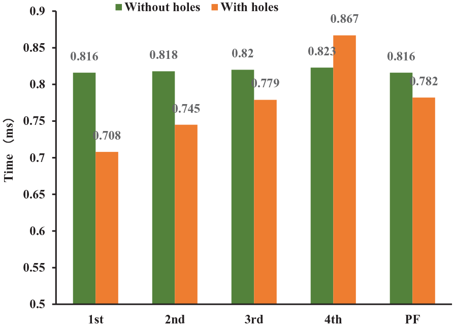
Fracture time of each layer and peak force time for the four-layered panel in scenarios with and without holes.
Effect on transverse deflection
In the present study, we mainly considered low-velocity perforation impacts. For high-velocity ballistic impact events, sufficient time was not present for obvious transverse deflection propagation to take place. However, for low-velocity impact events, sufficient time was present for transverse deflections to propagate and reach the fabric edges, resulting in creasing, and stretching over a wider region.
35
In other words, low-velocity impacts tend to extend and break the fabric rather than shear yarns, which are observed for high-velocity events. In a multilayer panel perforation impact event, primary yarns of each layer were stretched to a large extent and the fabric layer reached the maximum transverse deflection and failure. In this study, the maximum transverse deflection of the front layer at the corresponding fracture time for each layered panel for scenarios with and without holes were quantified by FE simulations to better compare the two scenarios; the third primary yarn (i.e. two yarns spacing from the center primary yarn) was chosen as an object, and the results are shown in Figure 12. The maximum deflection for the scenario with holes for each type of panel was clearly smaller than that without holes. Since hole defects were located in the central primary yarns, the third primary yarn plays the role of the first stressed yarn, which leads to a greater stress concentration, resulting in earlier fracture than that for the scenario without holes. Figure 12 also indicates that for the multilayer panel scenarios with and without holes, transverse deflection of the front layers was constrained by the back layers, and the constraining effect became more notable as the number of layers increased. This result is demonstrated in Figure 13, which shows that the fracture time of the front layer decreased as the number of layers increased for the multilayer panel, regardless of the presence or absence of holes. Furthermore, to compare the constraining effect on the two scenarios, the constraining effect index


Maximum transverse deflection of the front layer before fracture for each type of panel in scenarios with and without holes.

Fracture time of front layer in each type of panel in scenarios with and without hole.
These data are compared in Figure 14, which shows that the constraining effect becomes more severe for a greater number of layers for both scenarios. For the impact scenario with holes, the constraining effect was less severe than that without holes for all multilayer panel cases.

Comparison of
Effect on total energy absorption
In this study, the total energy absorption ET and the specific energy absorption (SEA) were calculated to examine the energy absorption of the panels with different amounts of material. SEA was normalized by dividing the total energy absorption by the corresponding areal densities of the panel, as indicated in equation (8):

where Ad is the areal density (g/cm2). These results are plotted in Figure 15. The results for scenarios with and without holes showed an increase in the total energy absorption as the number of layers increased in the armor panel, whereas SEA decreased when more fabric layers were present in the panel. Notably, for the scenario without holes, SEA decreased to 93.8%, 91.4%, and 90.2% the values of the single layer case for 2-, 3-, and 4-layer panels, respectively; for the scenario with holes, the SEA decreased to 95.5%, 93.9%, and 93.2%, respectively. This decrease was more severe for the scenario without holes than that with holes. Furthermore, the energy absorption ratios of the scenarios with and without holes were 54.1%, 55%, 55.6%, and 55.9% for 1-, 2-, 3-, and 4-layer panels, respectively. These data demonstrate that the difference in the energy absorption of the two scenarios narrowed as the number of layers in the armor panel was increased.

Total energy absorption and specific energy absorption for each type of panel.
In addition, for the multilayer panel, because the same fabric layers contributed to different amounts of energy absorption when placed at different positions, the energy absorption efficiency R was used for further investigations and is defined by equation(9): 36

where R is the energy absorption efficiency, Eith is the energy absorption of the ith layer in a panel, and Es is the energy absorption of a single fabric layer.
Figure 16 shows the impact energy absorption efficiency of each layer in the multilayer panels for scenarios with and without holes. These results indicate that regardless of the presence of a hole, the constraining effects on the front layers by the back layers became more notable for armor panels containing more fabric layers. Compared to the scenario without holes, the energy absorption for the scenario with holes have larger fluctuations between layers, the front layer was more severely constrained for each type of panel, and the back layer had a higher energy absorption rate.
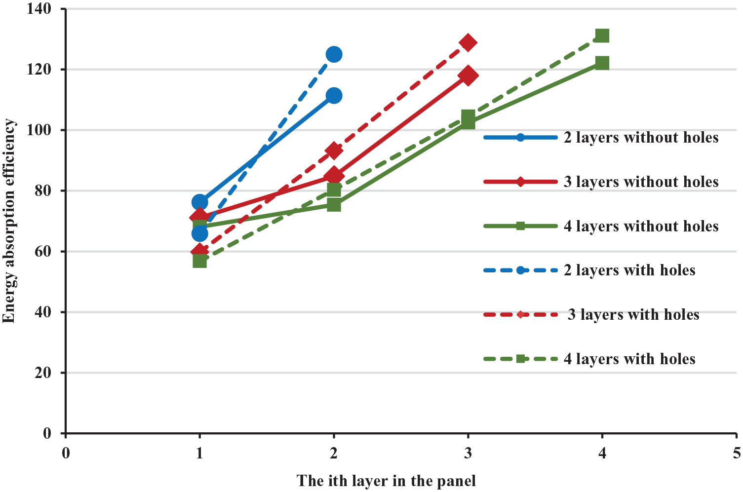
Energy absorption efficiency of each layer in each type of panel.
Influence of hole defects on different weaving architectures
Studies on the effects of holes on the impact behavior of fabrics with different weaving architectures were also performed for fabrics with plain, 4-harness satin, 2/2 basket, and 2/2 twill weaves, as shown in Figure 17. All the specimens with holes had the same configuration as the plain-woven model P3. The geometric parameters of various fabrics were kept consistent as much as possible to allow a comparison of only the effects of the architecture factor. In this study, the yarns in all architectures had the same cross-section and yarn spacing; the fabrics were constructed with identical thickness, length, and width, and the difference of their area density was almost negligible. The differences in the yarn interlacing pathway caused a higher yarn crimp rate for the plain weave than for the other three weaves. As shown in Figure 17, the yarns in the satin weave had the longest continuous float length, the basket weave and twill weave had the same length (second only to the satin weave), and the yarns in the plain weave had the shortest continuous float length. These geometric properties are listed in Table 4.

Schematic of different fabric models: (a) plain woven, (b) 4-harness satin, (c) 2/2 basket, and (d) 2/2 twill.
Geometry properties of different fabric architecture.

Effects on F–d curve
Contact force is the most important indicator reflecting a fabric’s impact resistance and is still one of the main factors to be studied. The F–d curve shown in Figure 18 suggests that for scenarios with and without holes, the plain weave fabric always had the highest maximum contact force. The maximum contact forces reached by the basket and twill weaves were very close; however, the basket weave was a little higher and second only to the plain weave fabric. The satin weave had the smallest maximum contact force. Conversely, the satin weave reacted most rapidly on impact because the contact force was always the greatest among all the fabrics over the same time before failure in both scenarios, whereas the plain weave reacted the slowest on impact. In addition, the deflection of the impactor at the time of fabric failure followed the same trend: the plain weave fabric had the greatest deflection for both impact scenarios, followed by the basket weave, twill weave, and satin weave. Notably, the basket and twill weaves had very similar F–d curves for both scenarios, especially before the fabric’s failure. Moreover, the twill weave specimen with a hole had better after-failure duration ability than the other three fabrics, as indicated by the largest difference between the failure time and complete failure time among all the scenarios with holes.

Comparison of the impact F–d curves of each fabric for scenarios with and without holes.
In general, hole defects drastically reduce the maximum contact force and simultaneously shorten the impact deflection at failure to a certain degree. The maximum contact force in the plain weave fabric with a hole was 49.3% that of the scenario without holes. The relative differences were 45.8% for the basket weave, 48.3% for the twill weave, and 45.6% for the satin weave. The impactor deflection at the time of failure for the scenario of the plain weave fabric with holes decreased to be 92.8% that without holes. The relative differences were 94.1% for the basket weave, 94.5% for the twill weave, and 89.7% for the satin weave. Overall, the satin weave was most notably affected, whereas the plain weave was least affected by hole defects in the contact force during impact event. In terms of impactor deflection at the time of failure, the satin weave was most notably affected, and the twill weave was least affected by hole defects.
Effects on transverse wave velocity
When an impactor impacts a fabric, two stress waves, namely longitudinal and transverse waves, are produced. The longitudinal stress wave propagates at the speed of sound of the material along the axis of the yarns, whereas the transverse wave propagation depends upon the impact velocity of the impactor and the material type. 37 The longitudinal wave velocity of a straight yarn depends on the yarn’s longitudinal Young’s modulus and volume density and is calculated to be greater than 7000 m/s for the Twaron® fabric. For a low-velocity impact event, within a very short instant, the stress wave propagates to a considerable distance from the impact center, while the stress applied in yarns remains quite small. Therefore, we infer that the influence of the woven architecture and hole defects was minimal on the longitudinal wave velocity; hence, in this study, we focus on the transverse wave velocity only because it is significantly slower than the longitudinal wave velocity.
When an impactor impacts a fabric, the transverse wave propagation results in transverse deflection in the primary yarns and causes the fabric to form a deformation zone, which becomes greater in size as the impact event progresses. Figure 19 shows a cross-sectional image of the side view deformation zone for each fabric at 0.3 ms for the scenarios with and without holes. A wider deformation zone simultaneously appeared, indicating that a faster transverse wave velocity was archived during the impact event. Hence, the transverse wave velocity decreased in the following order: satin > basket > twill > plain in the absence of a hole. Furthermore, the hole defect reduced the transverse wave velocity for all fabrics because a narrower deformation zone appeared at the same observation time. Notably, the transverse velocity of the twill weave surpassed basket weave and resulted in the transverse wave velocity decreased in the following order: satin > twill > basket > plain for the scenario without hole. Ordinarily, the velocity of the transverse wave propagation is calculated from the distance traveled by the stress wave from the impact point to the locations where the magnitude of the deflection becomes zero and the associated time. 38 Similar methods are applied in the present study by capturing the transverse displacement and associated time from the probed node located 20 mm away from the impact center along the central primary yarn of all fabrics for both scenarios. Figure 20 demonstrates the probed position. Figure 21 shows the time histories of the transverse displacement of the probed node; arrows indicate the arrival time of transverse waves of plain and satin weaves for the scenario without holes. In addition, the transverse wave velocities of all fabrics for both scenarios are calculated and shown in Figure 22. These results are consistent with the conclusions obtained in Figure 18; the satin weave had the fastest transverse wave velocity for both scenarios, whereas the plain weave had the lowest. This fast wave transfer was attributed to the longest continuous float length in yarns, in other words, the smallest number of cross-over points in satin weave, and inversely, plain weave had the most number. Furthermore, under the influence of hole defects, the transverse wave velocity decreased to 69.1%, 77.9%, 70.2%, and 72.6% the values of the plain, twill, basket, and satin weaves in the scenario without holes, respectively. The plain weave fabric was most affected in terms of transverse wave velocity, followed by the basket and satin weaves. The twill weave was the least affected by the hole defect.

Side view of impact deformation zone at 0.3 ms for different fabrics: (a) without hole and (b) with hole.

Schematic of probed node position

Time histories of transverse displacement of the probed node.

Transverse wave velocity of different fabrics.
Effects on total energy absorption
Many studies have confirmed that plain weaves outperform other fabric weaves in terms of energy absorption under high-velocity ballistic impact events.2,14 Because of the low-velocity nature of the impact events in this study (Figure 23), the plain weave similarly had the apparent highest energy absorption capability under both scenarios although the plain weave had a higher crimp rate than other weaves (the higher crimp rate counteracts the energy absorption owing to the decrease of the yarn’s tensile modulus). This result is attributable to the plain weave having the most firmly interlaced architecture. Furthermore, the transverse wave velocity in the satin weave was the fastest and that of the plain weave was slowest for both scenarios. The faster wave velocity implies that stress transferred more rapidly through the longitudinal direction to the boundaries. This weave architecture evidently results in the fastest reaction to impact. However, this architecture does not result in a greater energy absorption ability, but rather it performs poorest in terms of energy absorption in both scenarios. This is because the satin weave is not as firmly interlaced as the twill, basket, or plain weave. Hence, greater allowable movement is present between the yarns in the satin weave, making it easier for the impactor to push the primary yarns away and enabling easier and quicker penetration of the fabric. In addition, the basket and twill weaves have a higher number of cross-over points than the satin weave but fewer than the plain weave. These two architectures had very similar behaviors during the impact progress and had similar F–d curves, transverse waves, and total energy absorption, particularly for the case without a hole. Moreover, since it has the highest number of cross-over points, the plain weave can absorb a greater amount of energy despite having a slower reaction to the impact than the other three weaves.

Total energy absorption of each fabric in both scenarios.
As demonstrated in Figure 23, for the scenario without holes, the energy absorption capacity decreased in the following order: plain > basket > twill > satin; for the scenario with holes, the better after-failure duration ability of the twill weave afforded it better performance than the basket weave, while the rankings of two other weaves remained unchanged. By quantifying the effects of hole defects on each fabric, the total energy absorption in the plain weave in the scenario with holes decreased to 64.1% that of the scenario without holes, and it reduces to 67.5% in the twill weave, 58.1% in the basket weave, and 57.6% in the satin weave. The satin weave was the most affected, followed by the basket weave and plain weave. The twill weave was least affected by the hole defects in terms of energy absorption.
Conclusion
On the basis of a low-velocity drop weight impact model, which was validated by experiments, models of Twaron® single layer fabric with and without holes for multilayer fabrics (2-, 3-, and 4-layer) and different woven architectures (pain weave, 2/2 twill weave, 2/2 basket weave, and 4 harness satin weave) were created to investigate the effects of hole defects on the impact behavior of soft body armor. We obtained the following findings:
The numerical results of the low-velocity impact agreed well with the experimental results, suggesting that it is valid to use the proposed model to investigate the following problems.
The size and position of the hole defects affected the impact resistance ability. The impact resistance ability was lower for larger hole defects than for the smaller hole defects. The fabric model with a hole size of 3 × 3 yarn interweaving points can only take11.9% of the energy absorption of the model without holes. The impact resistance ability was the weakest when the hole defect was located at the impact center, and the hole defect of model with a hole located in 45° to the central primary yarn and the midpoint between the impact point and fixed boundary had the least effect on the impact resistance performance of the fabric.
Uninterrupted perforation and interval perforation characteristics were found as the impact progressed for panels without and with holes, respectively. A greater number of layers in the multilayer armor panel negated the influence of the hole defects in terms of the impact contact force, and less severe constraining effect was present on the front layer of the panel. Compared to the scenario without holes, the energy absorption for the scenario with holes was more dispersed over the layers. The front layer was more severely constrained for each type of panel, whereas the back layer had a higher energy absorption rate.
The plain weave fabric similarly had the apparent highest energy absorption capability among all weave architectures in impact scenarios with and without holes. Basket and twill weaves demonstrated very similar behavior in terms of impact progress, especially for the scenario without holes. The satin weave was most affected, whereas the plain weave was least affected by hole defects in terms of contact force during impact events. Moreover, the satin weave was the most affected and the twill weave was the least affected by hole defects in terms of impactor deflection at the time of failure and energy absorption. In addition, plain weave fabric is the most affected and twill weave is the least affected by hole defects in transverse wave velocity.
Footnotes
Declaration of conflicting interests
The author(s) declared no potential conflicts of interest with respect to the research, authorship, and/or publication of this article.
Funding
The author(s) received no financial support for the research, authorship, and/or publication of this article.