
Abstract
As soft elements for force transmission, braided fiber ropes play important roles in many fields where the fiber ropes are used bent over sheaves, while the relevant experiments are time-consuming and expensive. Computational simulation is a promising choice for evaluating the performance of fiber ropes when bent over a sheave. This article presents two methods that could be employed to build a model of braided rope bent over a sheave. One is the mathematical method which deduces the exact mathematical equations of braiding curves based on the Frenet–Serret frame. The spatial equations, considering the phase difference of strands in the same direction and the difference of strands’ projection in different directions, are discussed carefully. The final equation of braided strands is confirmed by modeling the braided rope in Maple® 17. The other method, which is inspired by the analysis of braiding movements, is based on the intersection of surfaces of braiding surface and helical surface which are introduced and defined based on the motion analysis of bobbins and take-up roller. The SolidWorks® 2018 is successfully employed to realize the modeling process.
Keywords
Introduction
As the force transmission tool, the steel wire rope has been in use since the 1500s when it was first invented. Besides its enough strength, the twisted structures render the steel wire rope soft enough to bend over a pulley or sheave. The soft and strong enough steel wire rope explored its application in many industrial fields, for example, crane, lift, mooring, and towing. With the development of deep sea and the deep space, long-distance ropes, which are longer than 3000 m, are needed to achieve the lifting or mooring functions. In this case, the traditional steel wire rope will not be still acceptable due to the lower ratio of strength to weight. In other words, the self-weight of steel wire rope will reduce the load-carrying capacity. In contrast, the synthetic fiber rope is significantly superior for long-distance lifting or mooring occasions. The density of most synthetic fibers is from 0.95 to 1.5 g/cm3, which is almost 1/7–1/8 of steel wire density. While the fiber rope and the steel wire rope with the same diameter almost have the same strength. Besides the higher strength-to-weight ratio, the synthetic fibers are more gentle to relevant pieces of equipment and workers due to its hairiness, which is generated when ropes bear abrasion.
Compared with the twisted structures of steel wire rope, the synthetic fiber ropes are mostly of the braided structure, which is more steady and safe. As strength elements, the rope bears great force when it works. Once the rope breaks, there would be decomposition in progress. For twisted rope, there would be a large destroy area due to the untwist trend, just like an umbrella. For braided rope, the strands are held by each other to form a steady structure; when it is broken, the rope just slashes back and will not form an umbrella-like appearance. So, the fiber ropes have a higher strength to weight ratio and great potential application in a long-distance occasion, such as the deep-sea mooring or lifting.
Due to these great advantages, the braided fiber ropes are more and more popular and replace the traditional steel wire rope in mooring and lifting conditions as show in Figure 1. These synthetic fiber ropes play more and more important roles and become the key elements in the marine and offshore industry. Compared with simple twisted structures of steel wire rope, the braided structures are formed by interweaving the strands in clockwise and anticlockwise direction. Owing to this kind of interweaving, the braided structures are more steady and complex. In recent years, scholars have built the static models and also gave the relevant mathematical equations. Although some papers considered the changes in cross-section of braided structures, all of these are straight models. As soft elements, the ropes are usually bent or tied to realize the transmission of force when they are used. Besides, the bent area is the weakest area for the whole rope when bending over a sheave or pulley. So, it is necessary to build the bending models of braided rope to conduct further researches on the fiber rope.

Application of braided rope in industries: (a) single mooring line, (b) towing line, (c) mooring line, and (d) crane rope.
This article introduces two kinds of geometrical modeling methods of braided fiber ropes: one is the mathematical method and the other is the geometrical method. For the mathematical method, the Frenet–Serret frame is employed to obtain the equations of braiding curve based on the relationship between secondary helix and braiding curve. The geometrical method is inspired by the analysis of the movements of the braiding process. During the braiding process, there are two parts involving the formation of braiding rope: one is the braiding bobbins which take the strands running along special paths; the other is the take-up roller which draws the braided rope away from braiding zone. The movements of these two parts could be decomposed into three sub-movements. By compositing these three sub-movements, the braiding surface and the helical surface could be obtained and these two surfaces contain all movements during braiding, so the intersection of these two surfaces is the braiding curve. The SolidWorks® 2018 is employed to realize the modeling process.
Literature review
Fiber ropes are of braided structure, which is an old and traditional art, while as the development of composites and in advanced application of ropes, this kind of structure has attracted lots of attention to its structures and performances. These researches include structural performances and structure analysis.
Computer-aided modeling of braided structures
The structure analysis of braided rope could be dated back to 1950s. Brunnschweiler 1 analyzed in detail the structure of diamond braid and developed its geometry based on ideal assumption. In this research, the braided strands were treated as the connection of line and circle, and this description of strands is not so exact compared with the reality. Leech 2 gave a numerical method for synthetic ropes with braided or twisted structure. He mainly focused on the mechanical performances based on the hierarchical relationship to give a prediction of rope performances with different structures or materials, with no detailed description of the specific braided structures. Wu et al. 3 focused on the double-braided synthetic fiber ropes and gave a detailed discussion on the structural modeling. In this work, the equation of the braided strand is carefully derived and then is used to calculate the strain and stress response. Wang and Wang 4 discussed the spatial distribution of yarns and mechanical properties in 3D tubular composites. The object of this research is about the 3D braids which are different from the braided structures. Zhang et al. 5 reported a 2D braided fabric considering the cover factor and other structural parameters including braid angle and helical length. Liao and Adanur 6 presented the 3D models of fabric reinforcement for composites and showed their braided models based on the Frenet–Serret frame; however, they did not give the specific equation for braided strands. Lomov et al. 7 created a truly integrated modeling and design tool for textile composites that include the braided structures. The method of the simulation is based on the defined points. Potluri et al. 8 produced three-dimensional shapes by braiding over a contoured mandrel and an expert system had been generated to take into account all the parameters interfacing with Virtual Reality Modeling Language (VRML) to simulate the braid geometry. With the development of computer graph theory, some scholars9,10 developed new methods that could cover the braiding structures over any manifolds. This method is effective and useful to obtain the braiding appearance but could not be used as the model to do the finite element analysis (FEA) analysis. Pickett et al. 11 developed a modeling method for finite element method (FEM) based on representative volume elements (RVE). This model was based on the plain weaving structures and could be used directly to FEM analysis. Based on the advanced software, the rope structures could be simulated by some scholars. Stanova et al.12,13 used CATIA and relevant tools to simulate the wire rope structures and also gave a relevant analysis of FEM. Ma et al. 14 simulated the wire rope bent over sheave based on ProE®. Alpyildiz 15 presented the equation of braided strands and also showed the simulation models based on a kind of description method. The braided models also could be built based on the computer programming methods. Kyosev16,17 developed a modeling system for braided structures based on the strand weaving patterns. Vu et al. 18 used a finite strain beam model to build the braided structures and conduct the FEA analysis. Based on this method, the strands in the rope could adjust themselves to avoid overlapping with each other. Ning and colleagues19,20 introduced a modeling method to realize the braided structures with different braiding patterns and braiding elements based on the generalized rose curve which was used to describe the projection curve of braiding strands; besides this method could also be used to realize the braided structures over non-cylindrical prisms. Shen and Branscomb 21 propose a general method to generate 3D representations of braided structures using explicitly expressed formulas.
Relevant researches on braided rope bent over a sheave
The study of the bending properties of fiber ropes begins with the bending performance of the yarn. Based on the ideal bending yarn model, Backer 22 first deduced the relationship between the fiber stress, strain, and curvature within the rope structure. Costello and Butson 23 built the simplified bending model of wire ropes based on ideal wire rope structures. Based on this model, a series of relationships are discussed including the stress, strain, and relative motion when bending over sheaves. Popper, 24 taking the fiber assembly as a research object, discussed the behavior of strands and fiber in the rope when bending over sheaves based on the analysis of friction between fiber and strands. Cornelissen and Akkerman 25 analyzed the nonlinear bending behavior of multi-stranded bundles and obtained the relationship between bending moment and bending curvature. Based on the model, a numerical simulation model is given to evaluate the effect of shear stiffness. Burgoyne et al. 26 introduced the results of fatigue testing of parallel aramid bundles under different pre-tensions. Hobbs and Nabijou 27 also conducted CBOS testing of aramid ropes and compared the results with those of high modulus polyethylene (HMPE) fiber ropes.Ridge28,29 designed a CBOS testing device for wire ropes and discussed the bending properties of wire rope under tension and bending; the relevant parameters and the failure mechanisms were discussed based on a series of experiments. Nabijou and Hobbs30–32 discussed the main problems in rope bending over sheaves, including relative motion, the friction in the rope, and other parameters that affect the bending fatigue properties of wire ropes. Sloan et al.33,34 referring to wire rope research discussed the effect of fiber material, coating, and rope structures on the rope bending fatigue life. In his research, the author emphasized the importance of thermal effects on bending failure and gave an improved rope bending solution. Based on experiments and theoretical work, Do Vu et al. 35 revealed the changes in stress and strain when fiber rope is bent over sheaves using finite element analysis.
While for these relevant research, some work focused on a mathematical calculation of braiding structures, others focused on the FEA application. The shape of the braided structures was not considered sufficiently. So, this article focuses on the bent rope with braided structures and gives the mathematical expression and mod methods. This work would be meaningful for relevant research work on the braided rope when bent over a sheave based on the FEA method.
Assumptions and geometrical definition of braided rope
To complete the mathematical modeling of braided structures, it is necessary to analyze the morphology of the strand and the relationship between braiding strand and helix and to define relevant surfaces and curves.
The relationship between the single helix and braiding curve
A strand in a straight braided rope is shown in Figure 2. Generally, the braiding curve helically goes around the rope axis similar to a single helix. The main difference is that the single helix goes up smoothly around the rope axis, in other words, the projection of the helix on the horizontal plane is a circle. As to the braiding curve, it goes around the rope axis and meanwhile in and out following the single helix. The projection of the braiding curve on the horizontal plane is a generalized rose curve. 19 The generalized rose curve is the projection of secondary helix, which means that the braiding curve and the double helix have the same projection. So, it would be reasonable to assume that the braiding curve is the projection of double helix on the helical surface which is formed by helically sweeping a line segment as shown in Figure 2.

The relationship among braiding curve, braiding surface, and helical surface.
The braiding curve could be obtained by projecting the secondary helix on the helical surface. The amplitude of the braiding curve is the same as that of the secondary helix. The secondary helical surface is built by helically sweeping a line segment along the single helix. The vertical surface is a surface that is vertical and passing the edge of the secondary surface. The intersection of the vertical surface and the helical surface is the braiding curve. That is to say, the braiding curve and the single helix are in the same helical surface and the braiding curve goes around the single helix with a sine-like pattern.
Basic assumption
Due to the comparative position relationship between strands and the rope axis, the equation of the bent strand could be obtained based on the following assumptions:
(a) The braiding curve is employed to represent the strand and the rope axis to represent the rope.
(b) During the bending process, the comparative position relationship between strands and the rope axis is not changed, that is to say, the braiding curve and the helix are still on the same helical surface.
(c) During the bending process, the cross-section of the rope keeps as a circle, and the rope has not been compacted.
(d) The mutual effects are ignored, which means the friction or other interactions will not be considered.
Definition of geometrical parameters of braided rope
To derive the equation of braiding curve, the following parameters concerning the braided rope should be defined as shown in Figure 3:
(a) The radius of the bent axis (Rc).
It is defined to reflect the bending degree and equal to the sum of sheave radius (Rs) and rope radius (Rr);
(b) Rope radius (Rr).
Rope radius refers to the size of the bent rope and would be measured as the distance from the rope axis to the projection circle of the helix.
(c) The amplitude of braiding weave (A).
This parameter is employed to describe the weave amplitude of the braiding strands and refers to the maximum of the distance in which the strand deviates the circle. In reality, this value equals the radius of strands.
(d) Braiding pitch (P).
The braiding pitch is the distance along the rope axis that one strand goes up or down in a whole circle.
(e) Helix angle/Braiding angle
The helix angle
(f) Braiding number (N).
It represents the number of strands in clockwise or anticlockwise direction within one pitch and also equals to the transmission time of a strand in and out of the braiding circle
(g) Rotational coordinate (αr).
The rotational coordinate is defined as the rotational angle from the starting point to the objective point on the rope axis around the sheave.
(h) Initial phase angle
The initial phase angle defines the starting point of the NO. i strand refers to the angle of sweeping from the 0 to the starting point on the initial plane.

The geometrical parameters for bent braiding rope. (I) Overview of the bent rope and (II) projection of a single braided strand on ZX plane.
Mathematical model of the bent braided strand
Based on discussions in section “The relationship between the single helix and braiding curve,” the braiding curve could be treated as the projection of secondary helix on the helical surface. According to this fixed relationship and assumption given in section “Basic assumption,” the space equation of the braiding curve could be obtained by employing the Frenet–Serret frame and then the whole models of braided rope could be realized.
For the fiber rope industry, many kinds of braided fiber ropes could be used in lifting or towing works, wherein a common kind of braided rope with diamond structures was selected as an example to conduct the modeling process.
When braided rope bent over a sheave as shown in Figure 3, there are three kinds of curves:
(a) The bent curve, taking on a form of a section of a circle, represents the rope axis bent over a sheave.
(b) The bent single helix. In rope structures, the braiding strand interweaves in and out of the braiding surface following this line. It would be helpful to understand the braiding trajectory and model the braided structures by using this auxiliary curve.
(c) The bent braiding curve is the centroidal axes of the braiding strand and employed to represents the strand.
Length of relevant curve and relationship among the rotational coordinates
To obtain the relationship among the rotational coordinates, the engineering drawing development approach is employed, which is based on the idea that projecting the centroidal axis on to a plane without stretching or shrinking. For bent curve and bent single helix, it would be easy to obtain the path length of the centroidal axis of the rope, the single helix, and the consequential relationships of rotational coordinates between the rope axis, single helix, and braiding curve:
(a) The length of the bent curve is

(b) The length of the bent single helix. The bent single helix is a single helix and has been assumed to have the same length as the straight helix. So, its length is
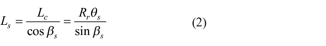
The rotational coordinate of the single helix
By substituting

Let
Derivation of the coordinate equation of the braiding curve
As described in section “The relationship between the single helix and braiding curve,” the braiding curve lies in the helical surface which is formed by horizontally sweeping a line that passes the axis and the single helix along the rope axis. When the rope is bent over a sheave, the axis is also bent, while the relationship between the braiding curve and the bent helix is not changed. In this case, the sweeping line is changed to the line that is vertical to the axis and passes the centroid point of the bent curve as shown in Figure 4. Based on this fixed relationship between the bent helix and bent braiding curve, the equation of the bent braiding curve could be derived.

Relative position relationship between the bent braiding curve and bent single helix.
Bent curve
When braided rope bent over a sheave, the rope axis would become a circle with the radius of Rc. In global Cartesian coordinate system, the parametric equation of the bent rope axis would be written as

where the bent circle lies on the XY coordinate plane and
Bent single helix
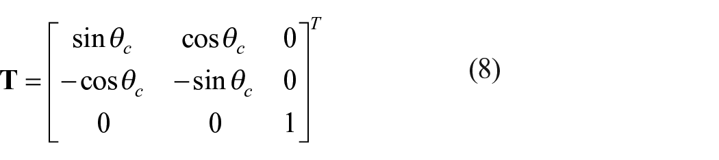
The Frenet–Serret frame describes the three vectors on a curve, the tangential vector
For the bent curve, the tangent vector

The normal vector

The vice normal vector is defined as

So the coordinate transformation matrix would be written from the Frenet–Serret frame
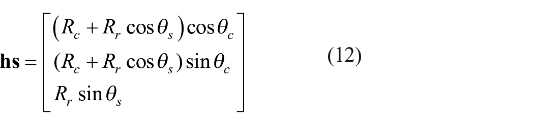
In the local coordinate system, the equation of a single helix is

When the single helix is fixed in the Global Cartesian system, the x-axis of the local Frenet–Serret frame should be in accordance with the vector

The bent single helix

By substituting equations (4) and (10) into equation (11), the formula of bent single helix could be written as
Considering the initial phase angle and the relationship between

Bent braided curve
The position relationship of bent braiding curve and the bent single helix is shown in Figure 4; the braiding curve lies in the surface formed by sweeping a line segment (LB) that is perpendicular to the bent curve and passing the bent curve and bent single helix. We call this surface as bent helical surface. Both the bent single helix and the bent braiding curve are on this surface. The braiding curve weaves along the single helix. Point L is on the bent curve, point H is on the bent single helix and point B is on the bent braiding curve. These three points are in the same line.
Based on the assumption, when the rope is bent over a sheave, the relevant position relationship would not be changed, that is to say, these three points are still on the same line. In this case

where the

Let

So, following the single helix, the braiding curve with the amplitude as A and the weave frequency as N within one turn, the equation of the bent braiding curve could be presented as
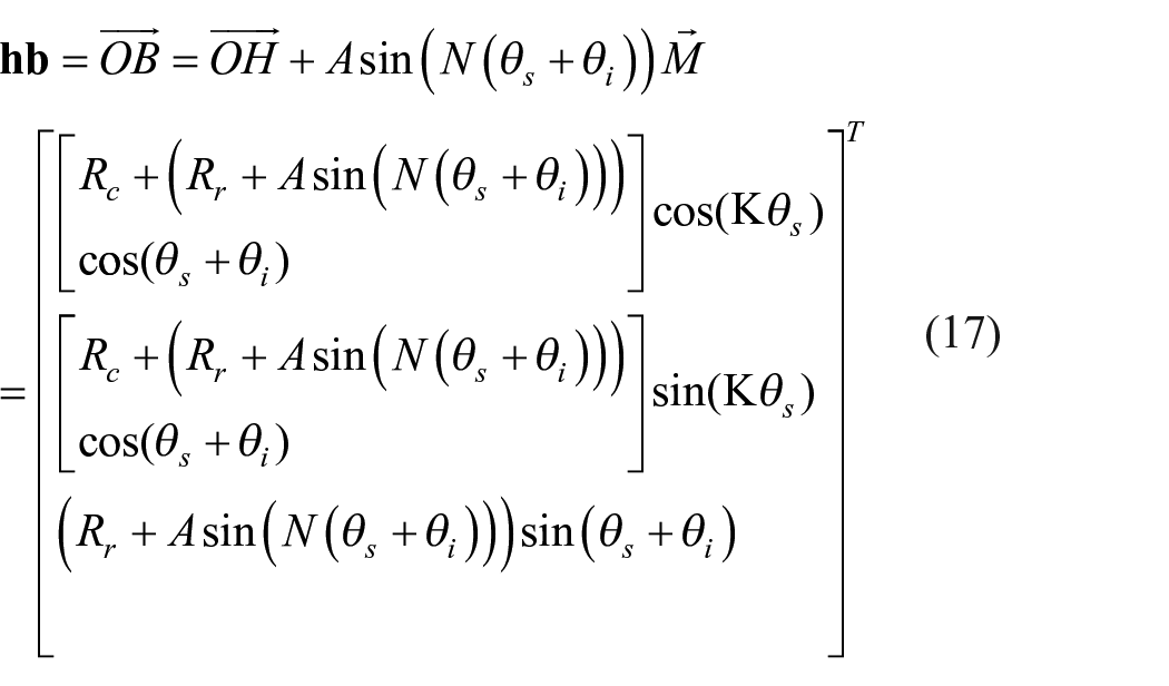
Equation (17) represents the bent braiding curve anticlockwise around the bent single helix. The bent braiding curve clockwise would be written as
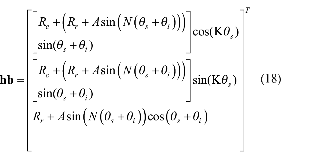
The equation of the bent braiding curve is very formal.
Based on equations (17) and (18), the mathematical model for braided rope bent over a sheave could be obtained. Taking the 12 strand braided rope as an example, there are 6 strands in the clockwise direction and 6 strands in the anticlockwise direction; these strands in different directions interweave one by one with each other. These 12 strands evenly distribute around the rope cross-section, which means the phase difference of adjacent strands in the same direction is π/3 and that of adjacent strands in different directions is π/6. This rope is bent over a sheave with a radius of 250 mm. Relevant parameters of this case are listed in Table 1.
Geometrical parameters for aimed bent braided rope.

The Maple® 17 was employed to realize this mathematical model as shown in Figure 5. From the mathematical model, it could be observed that the bent braiding strands weave each other well and keep the characteristics of braided rope and also reflect the validity of this mathematical model.

Bent braiding rope based on the mathematical equation.
Geometric modeling of braided strands based on mathematical models
Besides using the mathematical tools, the bent braiding structures also could be realized by 3D software based on the equation of the bent braiding curve. In this section, the popular 3D modeling software SolidWorks® 2018 is used as a tool to illustrate the modeling steps.
In SolidWorks® 2018, first, build a new “3D sketch” to ensure the curve is a 3D curve, not a 2D curve. In the 3D sketch window, the “equation driven curve” tool under the “spline” menu is selected as shown in Figure 6. Input the parameter equation of X, Y, and Z in terms of t, wherein the t is equivalent to the rotational coordinate

Detailed steps of the modeling process based on the parameter equation.
For the bent braiding curve in the anticlockwise direction, the phase difference is π/3, so the initial angle of the six bent braiding curves are 0, π/3, 2π/3, π, 4π/3, and 5π/3 respectively. For the bent braiding curves in the clockwise, the phase differences are also the π/3, while there is a phase difference of π/6 for adjacent bent braiding curves in different directions, which means the initial phases for bent braiding curves in anticlockwise direction are π/6, π/3, 5π/6, 7π/6, 3π/2, and 11π/6 respectively. Based on these data and equations (17) and (18), all the 12 bent braiding curves could be obtained.
After obtaining the bent braiding curve, the braiding strands could be realized by sweeping the cross-section of the strand along the bent braiding curves. First, an auxiliary plane that passes one end of the bent braiding curve and perpendicular to this curve needs to be created. On this plane, the cross-section of the strand could be drawn taking the intersection point of the auxiliary plane and curve as the center of the circle. Besides the circle as the cross-section, the other shapes, such as an ellipse or thin plane, could also be used.
All the strands are created in SolidWorks® 2018 as parts. The final bent rope would be created in the assembly section. First, an assembly file would be created. In this assembly, a position draft is created, which is employed to fix the positions of all the strands. Then, the 12 strand parts could be input in the assembly to form the final bent rope, as shown in Figure 7.

Assembly process of two direction strands.
Geometric modeling of braided rope based on the surface intersection
The mathematical method to build the bent rope needs to input the equations of all strands, which is hard work. In reference 16, a new braiding structure modeling method was released based on surface intersection by analyzing the braiding motion. This method could also be employed to realize the modeling of bent braiding rope.
The modeling strategy of the surface intersection method
During the braiding process, the strands move on the bobbins. There are two sub-motion for each strand: one is circumferential motion rope axis and the other is the radial motion which moves in and out to form the interweave with strands in another direction. At the same time, the take-up roller continuously draws out the braided structures from the braiding zone to form the braided structures. The movement of the take-up roller provides an axial motion to the braiding strands. So, the motion of strands could be divided into circumferential motion, radial motion, and axial motion.
According to the position of these three sub-motions, they could be divided into motions in the braiding plane including radial motion and circumferential motion and axial motion. The motions in the braiding plane are independent with each other. Both of them are simultaneous with the axial motion, thus they could compose with axial motion. The radial motion and the axial motion could comprise a motion that lies on a surface formed by sweeping the projected curve along the braiding axis; this surface is named as braiding surface. The circumferential motion and the axial motion could comprise a motion which lies on a surface formed by helically sweeping a radius along the braiding axis. This surface is named as the helical surface. The braiding surface and the helical surface include all motions of strands, so the strand could be obtained by the intersection of these two surfaces.
When the rope is bent over a sheave, the relevant positions of strands are not changed and both the braiding surface and the helical surface are bent with the rope and are of the same centroidal axis with the rope. So, the braided rope bent over a sheave could also be obtained based on the surface intersection method.
Geometric modeling of braided rope
Braiding surface
The braiding surface is obtained by sweeping the braiding cross-section along the bent curve and the braiding cross-section is a kind of generalized rose curve, which could be realized by mathematical method or by drawing. As shown in Figure 8, a circle (sketch 1) is created with the diameter of the rope. Then, a line segment (sketch 2) with the length of weave amplitude (A) is created on another plane that is perpendicular to the circle plane. A closed helical surface could be obtained by helically sweeping the line segment along the circle with a turn of 12, which is the turn of a strand in a circle. The generalized rose curve could be obtained by projecting the outline of this helical surface on the circle plane using “convert entities tool.”

Parameter setting and generation of the generalized rose curve using the surface sweep tool.
Taking the generalized rose curve as the sketch profile, as shown in Figure 9, the braiding surface could be obtained by sweeping the generalized rose curve along the bent curve which is the rope axis. All strands in one direction, taking the strands clockwise as an example, are on this braiding surface. For strands in the anticlockwise direction, the braiding surface is different. There is a phase difference, so the generalized rose curve is not the same one but has a phase difference of π/6. Similarly, the braiding surface for the strands in the anticlockwise could also be obtained by the generalized rose curve along the bent curve.

The generation of braiding surface.
Helical surface
The helical surface consists of take-up motion and perpendicular motion and is a kind of helical surface. This surface could be obtained by helically sweeping a line segment along the bent curve, as shown in Figure 10. The positions of the helical surfaces determine the positions and direction of strands. As described in section “Bent braided curve,” the initial phase angle of all strands could be fixed. Then a series of line segments could be drawn on the auxiliary plane to form Sketch 5. Taking this sketch as profile, the helical surfaces could be obtained by helically sweeping the profile along the bent curve in the anticlockwise direction.

Parameter setting and formation of helical surfaces.
For strands in the clockwise direction, the corresponding helical surface could be obtained considering the initial phase and the helical direction. The intersection curves of the braiding surface and the helical surface are the braiding curves. Following the method of the geometrical modeling process, the bent braided rope could be realized.
Conclusion
The mathematical model of bent braided rope is based on the projection relationship between the secondary helix and braiding curve. In detail, the braiding curve is assumed as the projection of secondary helix on the braiding surface which is formed by sweeping a line segment on a horizontal plane along the rope axis and this kind of relationship could not be changed when the rope is bent over a sheave. Under this assumption, the bent braiding curve could be treated as a sine curve around the bent single helix. The Frenet–Serret frame is employed to obtain the parameter equation of bent braiding curve based on this kind of relationship among bent single helix and bent braiding curves. The mathematical model of bent braided rope is checked and realized by Maple® 17. Based on the powerful 3D modeling function and the parameter equations of bent braided curves, the bent rope could also be obtained by SolidWorks® 2018. This method could deepen the understanding of braided structures while needing lots of inputs.
By the decomposition and re-composition of the strand motion during the braiding process, the surface intersection method is raised and used to realize the modeling of bent rope. The key steps of this method are to create braiding surfaces and helical surfaces. The SolidWorks® 2018 is employed again to realize this process. Compared with the mathematical method, this method is easier to operate.
The mathematical and geometrical models of braided rope bent over a sheave play different roles for further researches on this engineering case. The mathematical models are useful to value relevant displacements and movements during the bending process and the geometrical models could be used as the base for FEA to evaluate the stress distribution. These further investigations will be published soon.
Footnotes
Declaration of conflicting interests
The author(s) declared no potential conflicts of interest with respect to the research, authorship, and/or publication of this article.
Funding
The author(s) received no financial support for the research, authorship, and/or publication of this article.