
Abstract
The main aim of the presented tests was to assess the possibility of using 3D printing and casting material to produce casting molds and prototypes, especially in production of existing models. The analysis was based on the assessment of dimensional accuracy and quality of the surface layer of a finished prototype and the intermediate elements made during the production process. The mold was made using the PolyJet Matrix additive technology, and then a silicone mold was cast which was used to prepare a finished sample for testing in accordance with the design assumptions. Based on the results of metrological measurements, the phenomenon of technological inheritance in terms of error transfer in the foundry industry was evaluated. The measurements obtained suggest that in case of casting process, the hereditary features are transferred from individual casting processes, which is especially prominent in the case of surface texture quality. This confirms the occurrence of the phenomenon of the so-called technological inheritance and the need to analyze it. The results of the tests can be a guide for technologists who design molds, core boxes, and casting models, concerning the corrections (shrinkage) that need to be introduced at the design stage in order to obtain a product (casting) of satisfactory dimensional accuracy and quality of the surface layer. The result can also be useful for casting materials reinforced with glass fiber, carbon fiber, which are common materials in 3D printing and textile industry.
Introduction
Additive manufacturing technologies date back to the 1980s.1,2 Thanks to the development of CAD (computer-aided design) software, the next few years saw a very dynamic development of additive technologies using plastics, as well as metal and ceramic materials. Using additive manufacturing, designs based on three-dimensional (3D) solid models saved as STL (stereolithography language) files can be fabricated instantly. These technologies can be divided according to a number of criteria such as the way the layer is bonded (chemical, gluing, sintering) or the form of the input material (powder, liquid, solid). 3 Additive manufacturing has many practical applications, such as the production of prototype models, for further functional testing, production of injection mold inserts, 4 and production of fully functional models for short runs, with very satisfied mechanical and rheological properties.5–7 In addition, these technologies are used in the medical, 8 dental, textile, 9 automotive, aerospace, 10 and military industries.
Due to the very wide application of additive manufacturing technologies in the foundry industry, 11 technologies based on layer-by-layer schemes are used to build patterns for lost-material casting, for example, to make single-use casting molds for low-melt materials or casting molds used to produce final silicone molds. 12 The use of additive manufacturing technologies in the foundry industry significantly reduces the production time of the first test piece, as well as technology tests (gating system, feeders, cooling and molding process). In case of making any changes in the CAD model, it is possible to immediately print a mold or a pattern. 13 However, in some cases, it is difficult or even impossible to make finished patterns or molds using additive manufacturing technologies. The reason for this is that in the case of almost all additive manufacturing technologies using plastic-based materials that are currently present in the market, the melting point of these materials is low (typically not exceeding 200°C). Therefore, it is necessary to look for alternative manufacturing methods that can be used to produce the designed models efficiently and with satisfactory accuracy. The combination of additive manufacturing technologies and widely used silicone mold casting can address these challenges, enabling the casting from casting materials or high melting point materials such as aluminum, tin, copper, or bronze alloys. If a mold is made using 3D printing technology and next a sand mold (quartz sands) is produced based there upon, then the casting of cast steel- and cast iron-based materials is possible. In the case of casting plastic materials, mechanical properties can be improved using glass or carbon fiber additives, which is already a common practice in the construction industry (concrete components). 14
One of potential application areas of plastic additive technologies is the chemical industry. 15 In this article, authors present the results of tests carried out on models manufactured using 3D printing technology and biodegradable PLA (polylactic acid) material as well as electrospinning and polymer nanofibers. The tests results, in particular, the analysis of surface microstructure and chemical composition, showed that the combination of these technologies enables the production of composites with filtering properties, for example, chemical compounds.
When considering the molding and casting processes, one should notice a clearly visible phenomenon of transfer of certain features (defects) from the pattern to the casting mold, and consequently to the finished casting. If given features remain in the finished product, 16 then we are dealing with the phenomenon of the so-called technological heredity.17,18 The analysis of technological inheritance is extremely important for the manufacture of precision components such as rolling bearings.19–21 The modern foundry industry strives to create precise castings, which in many cases do not require further processing. Therefore, in addition to determining the size of defects that occurred at each stage of the molding and casting process, it is necessary to determine how the given deviations affected the individual stages of model development. Then, it is possible to perform some corrective actions (3D model, STL, selection of technological parameters, selection of pouring parameters) allowing to obtain finished products (castings) with a specified dimensional accuracy.
The main objective of the presented tests was to assess the possibility of using additive manufacturing technology of photocuring of liquid polymeric resins and casting plastics to produce casting molds and prototype models. For this purpose, the quality of the surface texture and the dimensional accuracy were measured at each stage of the manufacturing process. The analysis of the technological inheritance of errors occurring at particular stages of the manufacturing process was carried out, including the final sample. The analysis of the quality of final product may include the assessment of the dimensional and shape accuracy and the assessment of the surface texture, for example, multiscale surface characterization.22–25
The novelty of the presented tests results lies primarily in a comprehensive approach regarding dimensional and shape analysis and the assessment of the surface layer quality of models manufactured with conventional (casting) and unconventional technologies (3D printing), as well as their comparative analysis. In addition, the article examines both modern casting materials and liquid polymer resins currently used in 3D printing (PJM, “PolyJet Matrix”—one of the most accurate additive manufacturing technologies), which are an alternative to cast materials, which also constitute an element of comparison and novelty.
Methodology
Testing procedure
The testing was divided into several stages. The individual stages of the project are presented in Figure 1. The first stage was to design a 3D CAD model of a casting mold (CM1) using additive manufacturing technology. For this purpose, SolidWorks program was used. Then, the .STL model was created, which approximates the solid model with a grid of triangles. The approximation parameters have been selected so that the accuracy of the .STL model is greater than the accuracy of the machine used to print the mold. The “customized” recording mode was used, which was characterized by an angle tolerance of 5° and a linear tolerance of 0.01 mm. The model, thus, recorded was approximated with 172 triangles. The next step was to make a casting mold using the additive manufacturing technology of photocuring of liquid polymeric resins. Stratasys Connex 350 machine and FullCure 720 material were used for this purpose. A layer thickness of 0.03 mm was applied. The model was placed on the platform in such a way that its largest area adheres to the table plane. Each manufactured model (CM1, CM2, and finished sample) was produced in five pieces; the mean value of the results is presented in Tables 3 and 4. Then, linear dimensions were measured using the O-INSPECT Multisensor Coordinate Measurement Machine and surface texture was measured using the Talysurf PGI 1200 contact profilometer. In the next stage, using the CM1 mold, a silicone mold (CM2) was made (cast) using MM940 silicone from ACC Silicones. After curing the mold, metrological tests of the silicone mold were carried out. Tests of linear dimensions were carried out in the same way as in the case of CM1 mold. Surface texture measurements were carried out using the Talysurf CCI optical profilometer. As soft material was used to build the silicone mold, and difficulties with the surface texture contact measurement of the element surface were encountered. The key issue was to obtain an identical grid of measuring points for both instruments (optical and contact profilometer). In order for the measurement to be reliable and to be able to relate it directly to the measurement results from the contact profilometer, the same measurement and analysis conditions were maintained (the measurement was carried out in an analogous area, with the same sampling density, 0.8 mm cut-off, TalyMap Platinum software, Δx = Δy = 1.6 µm). One of the last stages of the testing was pouring of RenCast FC-52 liquid casting resin into the silicone mold. The last stage of the testing procedure was to perform metrological analysis of analogous features of the sample using the above-mentioned measuring instruments (O-INSPECT Multisensor Coordinate Measurement Machine and Talysurf CCI optical profilometer).

Block diagram of the testing procedure.
The presented block diagram (Figure 1) contains feedback loops, which can be used to correct process parameters in case of unsatisfactory results of dimensional accuracy and structure quality of the surface layer. The green arrows indicate the correct course of the manufacturing process of a finished model (characterized by the assumed dimensional accuracy and quality of the surface layer), while the red ones indicate the inconsistencies and show the need for correction. Such correction can be carried out in several stages depending on the source of the error. At each stage of the production process, the following should be taken into account: the possibility of incorrect 3D model design (CAD), incorrect model approximation with a triangle grid (incorrectly selected parameters of STL file—linear tolerance and angle tolerance), incorrect selection of technological parameters during the 3D printing process, and improper conditions of pouring and cooling of both the silicone mold and the final cast model. In addition, it is necessary to take into account, among other things, material shrinkage or measurement errors, which depend on both the type of the material and the manufacturing technology. Manufactured samples are presented in Figure 2.

(a) CAD design of the sample, (b) CAD design of the mold, (c) CM1 mold, (d) CM2 mold, (e) finished sample, and (f) completed elements.
Materials
In this article, FullCure 720 resin was used to build sample models. The material was delivered by Stratasys, manufacturer of the Objet350 (3D printer used to produce the samples). Due to low melting point, this material is used in the foundry industry to build single-use patterns in the lost-material method. In addition, the material is characterized by low shrinkage and dimensional stability. Table 1 shows the example mechanical properties of FullCure 720 (FC720) used for production of samples.
Mechanical properties of FullCure 720 resin.

Next, the mold was filled with MM940 silicone from ACC Silicones and reflected the final shape of the casting element. This material was selected because of its high flexibility, which makes it much easier to remove the cast sample. MM940 is a two-component silicone mass that cures at ambient temperature.
A catalyst in a ratio of 1:20 must be added to the standard material. After about 20 min, the material is cured. Elements cast from MM940 silicone can be used as parts to mobile robots. 26 Table 2 presents the mechanical properties of MM940 molding silicone.
Selected mechanical properties of the tested materials.

The last stage consisted of pouring RenCast FC-52 liquid casting resin into the silicone mold. It is a curable polymeric resin which is particularly recommended for thin-wall casting. If special fillers are used, it can also be used for casting elements of various thicknesses. This resin is available as two components: the basic resin (polyol) and the curer (isocyanate). Mixing the two components in a 1:1 ratio initiates a curing reaction that is completed in about 10 min. An unquestionable advantage of the elements cast from FC-52 resin is that it can be further processed, for example, by drilling, turning, milling, and grinding, to obtain details with higher dimensional and shape accuracy. Table 2 shows the basic parameters describing mechanical properties of samples made from FC-52 resin.
Results
Dimensional analysis of samples
The measurements of selected geometrical features (Figure 3) were carried out for the mold made using the PJM additive manufacturing technology (Figure 2(c)), for the silicone mold (Figure 2(d)) and for the finished model (Figure 2(e)). The results were compared with the nominal dimension values of the CAD design. The results of the measurements are presented in Table 3. In order to evaluate the phenomenon of technological inheritance, the coefficient |ΔX|, which is the relative error for the analyzed geometrical features, was calculated for each feature. The mean value, standard deviation, and coefficient of variation were calculated according to the equations presented in the studies of Adamczak and colleagues.19,20
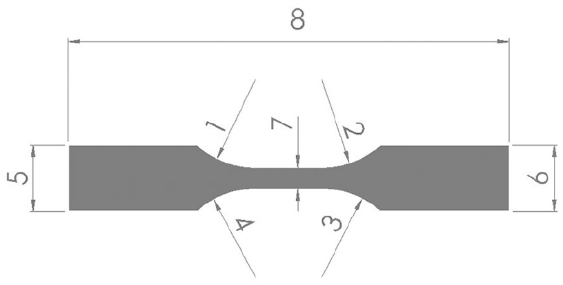
Geometrical features of the model.
Summary of the measurement results.

CAD: computer-aided design; CM: casting mold; SD: standard deviation.
By quantifying the results of the rounding radius measurements of the analyzed samples, we can conclude that in the case of the PJM printed mold, the radius dimensions in relation to the CAD model increased in value. The exception is Feature No. 1, where the values slightly decreased. This may be caused by the fabrication and polymerization process where, after spraying small droplets of liquid resin, the model material flows off at the edges of the model before the polymerization takes place. Based on the printed CM1 mold, the CM2 silicone mold was cast. With CM2 mold, the radius values compared to CAD and PJM (CM1) decreased, which is a natural consequence of the shrinkage phenomenon for this type of material. No clear conclusions can be drawn for the final sample because the values increased for two radii and decreased for the other two.
Analyzing the results obtained for the measurement of linear dimensions (sample width), it can be stated that for both the PJM additive manufacturing technology printed mold and the silicone cast mold, the linear dimensions decreased. Compared to the base CAD model, the greatest reduction was achieved for the silicone mold. This may be due to the silicone mold being cast based on additive manufactured mold. However, for the final sample made from FC-52 casting resin, the dimensions determining the width increased (on average by more than 5%). Therefore, when designing a casting mold using CAD software, the dimensions of the sample width should be reduced by approximately 5%. In the case of Feature No. 8 describing the sample length, a slightest change in dimensions occurred compared to the nominal model. Only for the silicone mold the sample length dimension decreased by 1.02 %. However, the length of the final sample in relation to the CAD model increased by 0.82 mm (0.13 %) only. This may result from the method of printing the casting mold used for making the sample. It should be added that the direction of movement of the head was parallel to the length of the mold printing, which resulted in the overflow of the material at the beginning and end of the mold in the process of spraying drops of material before the polymerization process took place. According to the Barishev classification of variability, it should also be stated that the variability of parameters is low when the coefficient of variation is less than 20%, thus the values are not significantly variable.
Analysis of the surface layer of samples
Advances in science and technology require a broad view of the process of shaping the surface layer of elements. Often an analysis of 2D surface profiles is not sufficient. The analysis of 3D outlines is therefore of key importance, with particular emphasis on spatial and volumetric parameters which play a major role in the process of wear, 27 which is the case with casting molds or injection inserts, including the additive manufactured ones.
On the basis of individual surface texture parameters, it is possible to obtain characteristic information about the tested 3D surface. In industrial practice, particular surface roughness parameters are used to describe the surface layer of elements manufactured with different intensities. For 2D profile analysis, roughness parameter Ra is widely used. Its expansion relating to the plane of the surface is not used universally. The height parameter Sa is replaced by the parameter Sq. In this article, we also analyzed the surface roughness height parameter Sku, spatial parameter Str, hybrid parameter Sdq, and volumetric parameter Vmc. All these parameters allow for a comprehensive assessment of the technological surface layer and characterize the usable properties of the finished elements of machine parts, directly determining the relationships between the cooperating assemblies.
The article determines the values of indicated parameters for the elements produced at individual stages of sample creation. Figure 4 shows an image of the surface roughness and waviness of the mold using PJM additive manufacturing technology (CM1). On the topography images, we can observe layers of the laid material that are characteristic for the PJM technology, resulting from spraying liquid resin drops along the head movement. After application, the drops are polymerized and cured, but for some time they settle in the layer, creating a characteristic texture (trace). Using the additive manufacturing technology, we produced a silicone mold (CM2) for which the images of roughness and waviness of the surface are presented in Figure 5. In the images, characteristic traces can be observed with structure similar to those visible in CM1 mold. This means that the individual features are transferred between the manufactured elements, which confirms the phenomenon of technological inheritance. The silicone mold was used to make a finished element whose surface topographies are presented in Figure 6 (surface that had direct contact with the silicone mold—Surface No. 1, Figure 2(f)) and Figure 7 (surface that had no contact with any other surface—Surface No. 2, “at the top,” Figure 2(f)). For Surface No. 1 of the sample shown in Figure 6, signs of transfer of irregularities from the previously made elements are also notable. It was advisable to carry out measurements of the surface texture on the corresponding areas in order to avoid randomness of irregularities of the surface of the produced details.

Topography images of CM1 mold surface: (a) roughness and (b) waviness.

Topography images of CM2 mold surface: (a) roughness and (b) waviness.

Topography images of Surface No. 1 of the sample: (a) roughness and (b) waviness.

Topography images of Surface No. 2 of the sample (on the top): (a) roughness and (b) waviness.
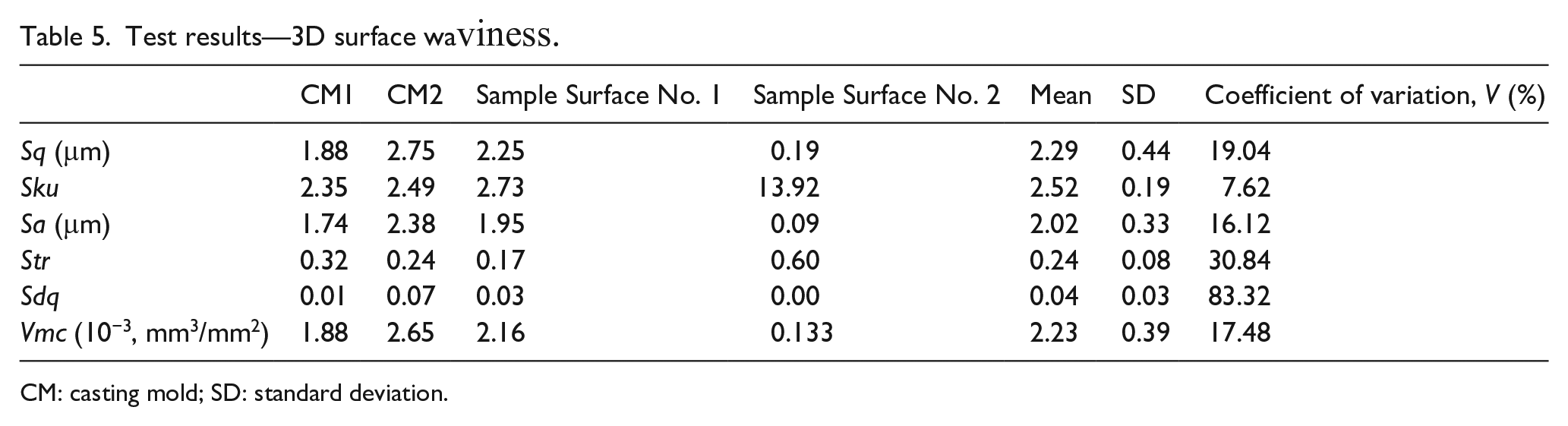
Based on the measurements carried out, the surface roughness parameters were determined. For each of the 3D parameter groups, a value of at least one selected index was determined. The results of the tests are shown in Table 4. The values of 3D waviness parameters, which are summarized in Table 5, were determined in a similar way. Moreover, in order to determine the interaction of surface irregularities of the produced elements (technological inheritance), the coefficient of variation (V) of values for particular parameters of roughness and waviness was determined. For this purpose, the additive manufactured mold, the silicone mold, and the surfaces of the sample that had direct contact with the silicone mold (Surface No. 1) were analyzed. The results of tests for Surface No. 2 of the sample, which had no contact with any mold, were presented in the table only for illustrative purposes and were not taken into account in determining the coefficient of variation.
Test results—3D surface roughness.

CM: casting mold; SD: standard deviation.
Test results—3D surface waviness.
CM: casting mold; SD: standard deviation.
Based on the analysis of the values of selected 3D surface roughness parameters, it should be stated that the values of height parameters decrease during the process of test sample manufacturing. Both the Sa and the Sq parameters strive for lower values. An analogous relationship was also obtained for the volumetric parameter Vmc. Based on the test results, it should also be stated that the character of the surface changed. For the surface of the silicone mold and for the surface of the sample (Surface No. 1), the values of the roughness parameter Str indicate that the surfaces are strongly anisotropic. However, for the surface of the additive manufactured mold (first stage of production, CM1), a much higher value of the parameter was obtained.
Both the values of surface roughness and waviness parameters change in a convergent way. In the case of the height and volume parameters of 3D roughness, it was noted that the values decrease at subsequent stages of the production process. The opposite situation occurs in the case of the waviness analysis of these parameters. The values of the sample created at the final stage are higher than in the case of the surface of the additive manufactured mold (first stage of the test sample manufacturing process). In accordance with the Barishev classification of variability, it should be stated that the variability of parameters is low when the coefficient of variation is less than 20%. The coefficient of variation value meets this criterion for both the height parameters (Sq, Sku, Sa) and the volumetric parameter Vmc of surface roughness and waviness. For spatial and hybrid parameters, the index shows average or high variability.
Analyzing the values of indexes for the surface of the sample which had no contact with any other surface (Surface No. 2), it should be stated that much lower values of 3D roughness and waviness parameters were obtained in comparison with other surfaces. This fact proves the good castability of the material and the high degree of filling of the mold by the FC-52 casting resin. It should be stated that the values of the individual parameters are at least one order lower than the values of the parameters for the other side of the sample. Particular attention should be paid to the Sku parameter which determines the kurtosis of the surface. For areas for which the ordinate distribution is in accordance with the normal distribution, the value of the Sku parameter is equal to 3. For the tested mutually shaped surfaces, the values of the parameter are similar and almost equal to 3. However, for the surface of the sample that had no contact with any other surface, the value is much higher. This indicates that a very smooth surface was created.
Conclusion
Based on the tests carried out and quantitative analysis of the examined parameters, it can be stated that additive technologies combined with conventional casting with the use of model plastics can be used to create short production runs, and especially to fabricate prototype models, which can be an alternative to time-consuming and costly conventional technologies.
The obtained values of individual 3D surface roughness and waviness parameters change at subsequent stages of sample production. Attention should be paid to the fact that in the case of height parameters and volumetric parameter of 3D roughness, it was noted that the values decrease with the progress of the production process. A contrary phenomenon was observed for the 3D surface waviness. Nevertheless, the values of individual indexes vary slightly.
High variability of parameters was recorded for hybrid and spatial parameters. The selected parameters change in an ambiguous way. Since individual surfaces of the cooperating elements of machine parts interact with each other during operation with their whole surface (both waviness and roughness surface), it is advisable to extend the testing by the analysis of the original (measured) surface.
Analyzing the change in linear dimensions of the casting mold made with the PJM technology and that cast from silicone, it can be concluded that in relation to the assumed nominal dimensions (CAD), they became lower. However, when considering the dimensions of the final casting, it can be stated that in relation to the nominal dimensions, the results increased by an average of 5%. The smallest change was noted for the dimension determining the sample length. Dimensional analysis of the test results is an indication to designers that when designing a casting mold using CAD software, the dimensions of the sample width should be reduced by approximately 5%.
Summarizing the obtained results of metrological measurements, it can be stated that in case of casting process, the hereditary features are transferred from individual casting processes. This is especially visible for the results of the surface texture analysis. This confirms the occurrence of the so-called technological inheritance phenomenon and the need to analyze it.
The presented tests are preliminary to broader research works aimed at the analysis of the technological inheritance phenomenon in the process of creating casting molds and castings. In further research, the authors will design a complex casting mold (containing geometrical features allowing for complex dimensional and shape analysis), which will be subjected to metrological tests. The results of the tests will provide valuable design guidelines for designers and technologists making casting molds using the increasingly common additive manufacturing technologies. In addition, a detailed analysis of the phenomenon of technological inheritance will enable evaluation of the degree of transfer of defects from individual casting stages and will allow for the introduction of preventive measures.
Footnotes
Declaration of conflicting interests
The author(s) declared no potential conflicts of interest with respect to the research, authorship, and/or publication of this article.
Funding
The author(s) received no financial support for the research, authorship, and/or publication of this article.