
Abstract
We present a bicontinuous, minimal surface (the helicoid) as a scaffold on which to define the topology and geometry of yarns in a weft-knitted fabric. Modeling with helicoids offers a geometric approach to simulating a physical manufacturing process, which should generate geometric models suitable for downstream mechanical and validity analyses. The centerline of a yarn in a knitted fabric is specified as a geodesic path, with constrained boundary conditions, running along a helicoid at a fixed distance. The shape of the yarn’s centerline is produced via an optimization process over a polyline. The distances between the vertices of the polyline are shortened and a repulsive potential keeps the vertices at a specified distance from the helicoid. These actions and constraints are formulated into a single “energy” function, which is then minimized. The yarn geometry is generated as a tube around the centerline. The optimized configuration, defined for a half loop, is duplicated, reflected, and shifted to produce the centerlines for the multiple stitches that make up a fabric. In addition, the parameters of the helicoid may be used to control the size and shape of the fabric’s stitches. We show that helicoid scaffolds may be used to define both knit and purl stitches, which are then combined to produce models of all-knit, rib, and garter fabrics.
Keywords
Introduction
The calculus of variations is the cornerstone of classical mechanics, elasticity theory, and modern economics. When problems are formulated as optimization problems, the equations governing motion, bending, or trade (respectively) describe critical points of the objective function. 1 When applied to geometric objects, this perspective is especially powerful. When the objective depends on geometric quantities, the minima, maxima, and other extrema are likewise geometric. Functionals of length lead to geodesic equations (shortest length), while functionals of area lead to minimal surfaces. Soap bubbles, for instance, minimize their area subject to a volume constraint leading to Plateau’s classic rules for foams.2,3 Minimal surfaces also appear in biological and self-assembled systems where surfactants and lipids create area-minimizing, space-filling structures, so called triply periodic minimal surfaces (TPMS). 4 Examples of these include the plumber’s nightmare, the gyroid, and the diamond surface. All three of these surfaces divide space evenly into two regions and can be thought of as a pair of interwoven passages with sixfold, threefold, and fourfold connectivity, respectively. 5
Since minimal surfaces are the solutions to many extremal problems in physics,6,7 we posit that they may be used to define the topology and shape of yarns in a weft-knitted fabric. In previous works,8,9 we demonstrated, with physical prototypes, how yarns of a weft-knitted fabric may lie on a scaffolding of alternating left- and right-hand helicoids, a type of minimal surface, with the form of the helicoids producing the characteristic spatial relationships between the yarns. Here, we present the mathematics and algorithms that create geometric models of the yarns making up a weft-knitted fabric, which exploit the lattice-like structural features of bicontinuous helicoid surfaces. The centerline of the yarn is specified as a geodesic path, with constrained boundary conditions, running along a helicoid at a fixed distance. The yarn geometry is then generated as a tube around the centerline. The helicoid therefore acts as a scaffold on which to define the shape of the yarns and their intertwinings. In addition, the structure of the helicoids maintains the proper spatial and topological relationships between yarns in the fabric.
The shape of a yarn’s centerline is produced via an optimization process over a polyline. The polyline is initially placed over a helicoid in the approximate configuration that will define a half loop of a stitch. The distances between the vertices of the polyline are shortened and a repulsive potential keeps the vertices at a set distance from the helicoid. In addition, the locations of the polyline’s endpoints are constrained. This process effectively models the shrinking of the initial polyline, while performing collision detection/avoidance with the scaffold surface, producing a geodesic path along the helicoid. These actions and constraints are formulated into a single “energy” function, which is then minimized. 10 The optimization process modifies the vertices to produce a minimum energy configuration that balances the inter-vertex stretching energy with the repulsive energy from the helicoid. This configuration, defined for a half loop, is then duplicated, reflected, and shifted to produce the centerlines for the multiple stitches that make up a fabric.
We see helicoid scaffolds providing a framework for simulating the weft-knitting process and for modeling/predicting the topological structure and geometric shape of the yarns in the resulting fabric. The work here lays the technical foundation for a planned effort to simulate weft-knitting with helicoid segments that represent needles in a knitting machine. The model will offer a geometric approach to simulating a physical manufacturing process, which should generate geometric models suitable for downstream mechanical and validity analyses.
Related work
The early work on modeling knitted textiles focused primarily on defining and analyzing the geometric structure of knit stitches.11–13 Remarkably, this work was done without the mathematical infrastructure of splines, 14 which was not widely available until the 1970s. Much later work did utilize splines to describe the centerlines of yarn geometry in knitted materials.15–19 Follow-on research applied minimum energy analysis to determine the shape of relaxed yarn loops in individual stitches,20–23 as well as larger bulk properties of plain-knitted fabrics.24–26 This work was extended by Kyosev et al. 27 to include the compression of the yarns in the loop. Sherburn 28 developed a modeling approach/system that works on microscopic, mesoscopic, and macroscopic scales to predict the mechanical properties of textiles. It numerically models the behavior of yarns and the interactions between them to produce simulation results. Duhovic and Bhattacharyya 29 simulated the knitting process in order to understand how each of a yarn’s deformation mechanisms contributes to the overall deformation energy/behavior of a yarn in a knitted fabric.
The first system to model and visualize complete knitted fabrics was developed by Meissner and colleagues.30,31 Their system (KnitSim) accepts Stoll knitting machine commands (knit a stitch, transfer loops between beds, and rack the beds) and simulates the knitting process to produce an explicit topological representation of a knitted fabric. By making assumptions about the length of yarns between yarn crossings, a relaxation process is run to produce a realistic two-dimensional (2D) geometric layout for the fabric.
In ground-breaking work, Kaldor et al.32,33 simulated complete swatches and articles of clothing consisting of knitted fabrics by modeling the geometry and physics of individual yarns in these items. This work was extended by Yuksel and colleagues34–36 to produce Stitch Meshes, an approach to generating Kaldor-style, yarn-level geometric models of knitted clothing from polygonal models that represent the clothing’s surface. Aspects of this work were utilized by Leaf et al. 37 to produce an interactive design tool for simulating yarn-level patterns for knit and woven textiles.
Cirio et al. 38 defined a topological representation of knits consisting of a limited set of stitches, in contrast to the yarn-geometry-based approach of Kaldor et al. They developed a mechanical model based on the representation for the simulation of knitted clothing. Liu et al.39–42 performed finite element modeling (FEM) simulations of knitted fabrics with solid yarn-level geometric models. Poincloux et al. 43 utilized an empirical model to simulate the mechanical behavior of knitted fabrics.
Techniques have also been developed for generating production data directly from surface models for the manufacture of knitted artifacts. Igarashi et al.44,45 developed a technique for generating hand-knitting patterns from three-dimensional (3D) models, along with an interactive design and visualization system. McCann and colleagues46–48 have developed algorithms that can generate knitting machine commands based on a variety of polygonal models as input. Their algorithms allow for the interactive design of 3D shapes, which can then be manufactured on a commercial knitting machine.
Our work stands apart from previous work in that we show that the problem of generating geometric models of yarns in a knitted fabric may be solved as a geometric problem itself, without the need for complex physical simulations of the knitting process. The natural, parameterized shape of the yarns is produced automatically by laying them along minimal surfaces. The helicoid scaffolds directly enforce the correct topology of the yarns without recreating the knitting processes that generate the knitted fabric. Changes in the stitch pattern, such as rib or garter, also necessarily result in an appropriate change in the loop shapes and topological relationships to neighboring loops. These conditions are enforced by maintaining the distinct yarn paths on separate sides of the helicoids.
Helicoids and the weft knit structure
Knit fabrics consist of a series of intermeshing loops of yarn and can be produced by hand or by machine. Each individual loop in the fabric is known as a stitch, and these stitches can be varied by the direction in which the loops are formed. A knit stitch is created when the yarn is drawn through a previous loop from back to front, and a purl stitch is created when this process occurs instead from front to back. These stitch types are structurally symmetric; therefore, a fabric made with all knit stitches is topologically the same as a fabric made with all purl stitches. Looking at the yarn patterns visible on the surface of the fabric, knit stitches can be identified by a “v” shape, while purl stitches can be identified by a horizontal line of half circle shapes (see Figure 1(a) and (b)).

(a) Knit stitches, (b) purl stitches, (c) rib fabric, and (d) garter fabric.
These two stitches can be combined in numerous patterns to form fabrics with wide variations in structure and behavior. 49 For example, textiles consisting of alternating columns of knit and purl stitches are rib fabrics, while textiles made up of alternating rows of knit and purl stitches are known as garter fabrics (see Figure 1(c) and (d)).
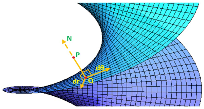
Two helicoids positioned side-by-side and twisting in opposite directions provide the scaffolding needed to define the loop of yarn in a single knit stitch (see Figure 2). These small sections of helicoids can be stacked on each other and replicated in columns to provide the scaffolding needed for the stitches in a knitted fabric, as seen in Figure 3.

Single loop of yarn laid out on two helicoids.

(a) Helicoids are replicated and shifted to create scaffolds, (b) a yarn flows through the scaffold in the course direction, and (c) and (d) are front views of (a) and (b).
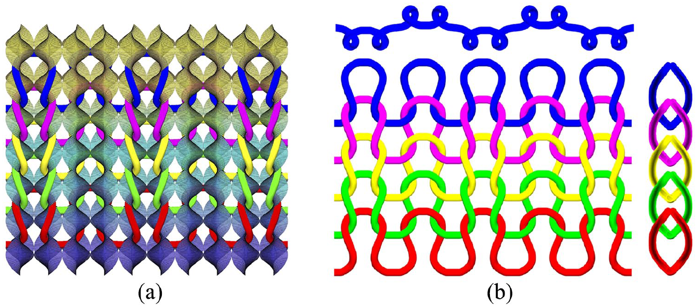
When defining fabrics consisting of just one stitch type, either knit or purl, a single row of paired helicoids is sufficient for laying out the geometry (see Figure 4(a)). When creating fabrics consisting of a mix of knit and purl stitches, two rows of reflected helicoids are necessary. In order to represent a rib fabric on helicoids, the yarn must travel from a “front” helicoid pair, for a knit stitch, to a “back” helicoid pair for a purl stitch. The transition from the front helicoids to the back occurs over the “legs” of the loop (see Figure 4(b)). For garter fabrics, the yarn must also cross from one row of helicoids to another, but in this case the legs of each loop are attached to one row of helicoids and its head is attached to the other (see Figure 4(c)).

Top view of fabrics on helicoid scaffolds: (a) all-knit, (b) rib, and (c) garter.
Helicoid mathematics
While a helicoid can be defined as the Riemann surface of the natural logarithm of a complex variable,
9
for this work we equivalently define it as a biparametric surface in polar coordinates,

where


Figure 5 presents a helicoid with parameter values

Helicoid defined with parameter values
Distance from helicoid
In order to find an optimal path for the yarn on the helicoid, the minimum distance from each point on the yarn to the helicoid needs to be computed. The yarn path is initially defined as a Catmull-Rom spline. 14 The spline is discretized into a finite number of points, thus approximating the yarn path with a polyline.
Approximate distance
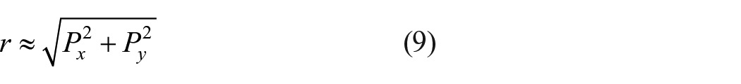
In order to speed up the optimization calculation, we developed an algorithm for computing an approximate distance to the helicoid. In Figure 6,


Approximate distance computation. The distance between
where
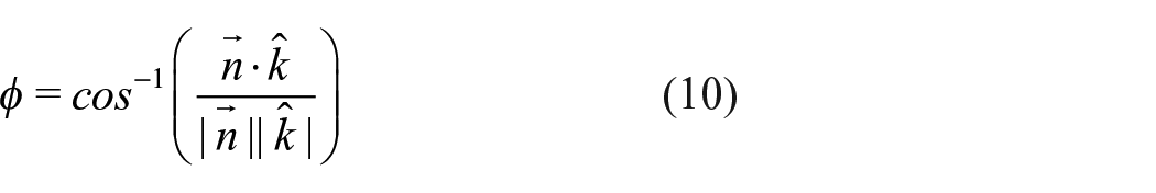
The normal to the helicoid surface can be computed as the cross product of the two tangents, given in equations (2) and (3)


where
The line

As seen in Figure 6, line

This only approximates the distance between the point

Accurate distance
Since the previous calculation is approximate and introduces some error, because it is based on the invalid assumptions that the
For each point
Since the vector
Given a point

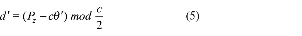
This can be simplified to produce an equation for

Similarly, substituting the angular tangent vector from equation (3) into equation (15) produces

Simplifying this equation and substituting

Equation (19) is a non-linear equation in
There are however infinite solutions to equation (19), since there is one point

Distance to a left-handed helicoid
A left-handed helicoid (where

In the previous sections, the distance between a given point and a right-handed helicoid was computed. To find the distance between a point and a left-handed helicoid centered at
Distance from a point lying outside the helicoid’s circular projection
In the previous sections, the computed distance to the helicoid from a point

If this is not true, the distance must be computed from

Yarn path generation
The shape of the yarn path is governed by different forces acting on the yarn, each of which is defined by a separate energy term. The yarn is repelled from the helicoid, while its length is shortened, which effectively stretches it across the surface. Thus, the yarn path stabilizes when the energies are balanced and it becomes as short as possible without penetrating the helicoid.
Computing yarn energy
The total energy of the yarn is the sum of the energies computed at

The reason for not computing an energy at the last vertex will be apparent given the definition of the length energy. The total energy associated with vertex

where

where

we normally set
The center of the yarn should never be less than

The distance energy is only computed for
Initialization and energy minimization
In order to produce an optimized yarn path on a helicoid, an initial path is specified with a Catmull-Rom spline around the helicoid (see Figure 9(a)). In our examples, the spline is discretized into a polyline of approximately 150 points. An optimization is run that minimizes equation (23) using the approximate distance calculation in the “Approximate distance” section. The resulting yarn polyline is close to the true solution, but with some regions that penetrate the helicoid. This approximate configuration then becomes the initial conditions for another optimization process, but using the accurate distance calculation instead, which produces the final, correct configuration (see Figure 9(b)). This two-step process provides about a
Yarn generated by initial and optimized set of points: (a) initial (front and back) and (b) optimized (front and back).
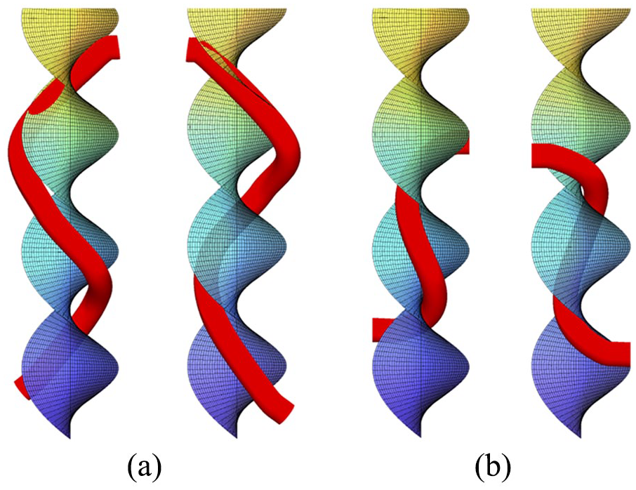
The resulting yarn geometry specifies a half-loop of a knit stitch, which can be reflected to produce a full loop, as in Figure 2. In order to define purl stitches that connect to knit stitches, a second plane of reflected helicoids is needed. The initialization and optimization of the yarn used in a garter fabric (alternating rows of knit and purl stitches) is slightly different, since a garter half loop spans two helicoids, one behind the other. This specific loop is needed in order to model how a knit stitch transitions into a purl stitch going in the upward (wale) direction. With the right-handed helicoid centered at the origin, the left-handed one is centered at
Initial and optimized yarn for garter stitch: (a) back view of initial yarn, (b) back view of optimized yarn, (c) side view of initial yarn, and (d) side view of optimized yarn.
Complete initial and optimized garter loop: (a) initial yarn and (b) optimized yarn.
Constraints and replication
A number of constraints are imposed on the optimized yarn in order to enforce the boundary conditions that then allow for the half loop to be continuously replicated. They are as follows:
The Y-coordinates of the endpoints are fixed to be equal to the helicoid radius. This ensures that the endpoints of the yarn are held at
The X-coordinate of the lower endpoint is fixed to be equal to the helicoid radius. This allows for the loop to connect with a yarn coming from a helicoid in a different x-plane, a boundary condition needed to produce rib structures.
At both endpoints, the second point from the end has the same X and Z coordinates as the endpoint. This ensures that the tangents at both half-loop ends are parallel to the Y-axis, a boundary condition that produces C1 structures.
With these constraints, the optimized half loop of the yarn can be easily replicated to obtain a complete loop, by reflecting it across the
In order to represent a rib fabric (alternating columns of knit and purl stitches) on helicoids, the yarn must travel from a “front” helicoid pair, for a knit stitch, to a “back” helicoid pair for a purl stitch (see Figure 4(b)). A model of a rib fabric can be generated from a model of an all-knit fabric by reflecting alternating columns of stitches across the
A model of garter fabric can be generated by first duplicating and shifting the necessary number of garter full loops (Figure 11). This loop represents a knit stitch in a garter fabric. The loop is then simply reflected across the
Given the two optimized loops, a geometric model of a knitted fabric consisting of an arbitrary combination of knit and purl stitches may be generated. If a given stitch (knit or purl) has a different stitch above it, the garter loop of Figure 10(b) is used to represent the stitch. Otherwise, the plain loop of Figure 2 is used. The stitch type will determine if the geometric loop is positioned on the front helicoid (knit stitches) or the back helicoid (purl stitches). See Figure 18 for an example.
Physical accuracy experiment
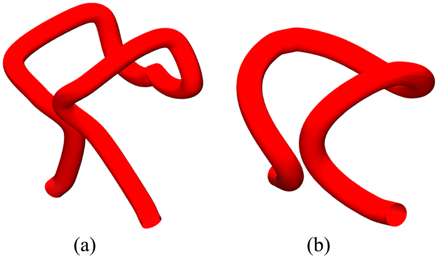
We conducted an experiment to investigate the physical accuracy of the models generated by our approach. The experiment involved minimizing the bending energy of the polyline after removing some of the constraints. The yarn’s length, endpoints, and the tangents at those endpoints are kept fixed while the distance from the helicoid energy is removed. Removing this energy leaves the polyline free-floating without any interaction with the helicoid. The minimization is done on a half stitch and the result is then mirrored and joined to obtain the complete stitch.
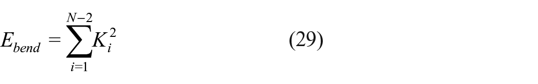
Curvature at each polyline vertex is computed using the following equation

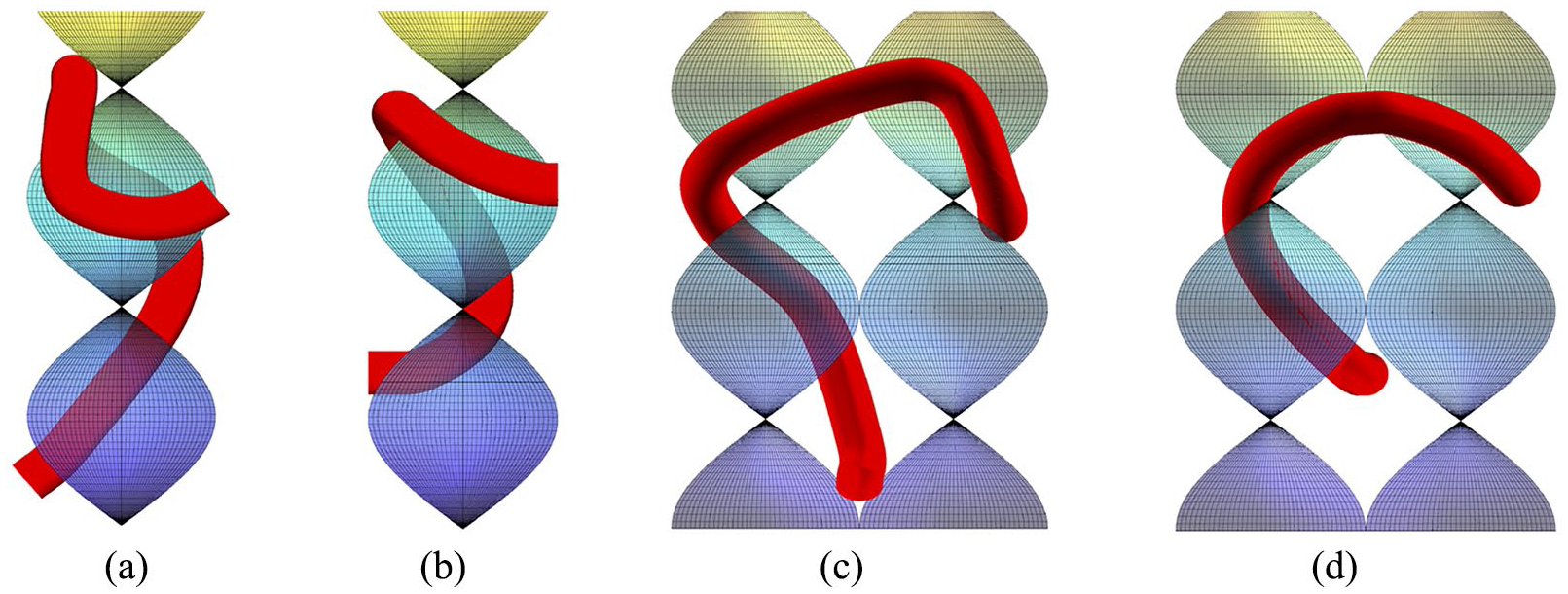
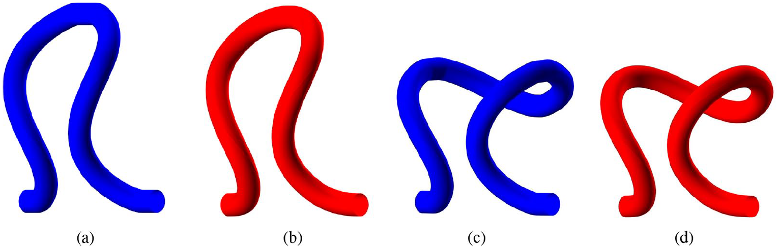
This energy is then minimized by moving the vertices of the polyline while keeping the endpoints of the half stitch and their tangents fixed. The results of the optimization obtained by mirroring and concatenating the optimized half stitches are shown in Figures 12 and 13. Figure 12 shows the knit and garter loops before and after minimizing bending energy. It can be seen that the major changes after optimization occur at the regions where the models were outside the helicoid projections. Figure 13 shows the overlayed models for both stitches and highlights the minimal differences between the models.
Knit loop (a) before and (b) after optimizing for minimum curvature. Garter loop (c) before and (d) after optimizing for minimum curvature.

Overlapped models before and after optimizing for curvature: (a) knit loop and (b) garter loop.
This experiment shows that generating a geodesic path on a minimal surface produces yarn geometry that is in a stable mechanical configuration. Minimizing the curvature-squared would force an unconstrained polyline to become straight, but given the constraints on the endpoints, a much more complex 3D shape is produced. Since the yarn geometry only slightly moves after minimizing the total bending energy of the polyline, it can be deduced that our helicoid scaffold approach, which is based on a purely geometric calculation, produces a result that is in a mechanical, that is, physical, energy minimum state, thus supporting the argument that modeling with minimal surfaces produces physically accurate geometric configurations of yarn geometry.
Results
Computation time
All geometric models included in the article were generated on an Apple iMac with a 4.2 GHz Intel Core i7 processor and 32 GB of RAM. The computations were done in MATLAB using the unconstrained optimization function fminunc, with parallel computing enabled which allows for simultaneous processing on all four cores of our system’s CPU. The generation of the optimized half-loop yarn model dominates the computation time of our approach. While the time needed to produce an inaccurate result, as seen in Figure 14(a), is only 30 s, generating the accurate result of Figures 2, 9(b), and 14(b) requires 22 min. This increased time comes from the separate optimization needed for every distance-to-helicoid computation that is performed for every point in the polyline during every iteration of the global optimization process. These computation times did not change significantly with changes in the model’s parameter values.

Yarn path obtained using the (a) fast approximate distance calculation method and (b) the compute-intensive accurate distance calculation method.
We use a hybrid approach that first employs the fast inaccurate distance method to bring the initial polyline (Figure 9(a)) close to the surface, which is followed by a polyline refinement using the accurate distance calculation to bring the yarn model onto the surface. The hybrid approach provides significant speed-ups over computations that exclusively use the accurate distance calculation for the whole process. Employing only the accurate distance calculation to produce the final results in Figures 2, 9, and 14 requires 84 min of computation time. Since the hybrid approach requires only 22 min, it provides about a
Approximate versus accurate results
Figure 14 presents the different results produced by the approximate distance computation method and the accurate method. When using the approximate method, it can be seen that the yarn penetrates into the helicoid to a depth of around 10% of the yarn radius. When using the accurate method, no visible penetration is observed.
Different fabric examples
Figures 15(a), 16(a), and 17(a) present the yarn geometric models lying on helicoids generated by our approach for all-knit, rib, and garter fabrics, respectively. The yarn models with the helicoid scaffolds removed are presented in the (b) subfigures of these same figures. Figure 18 presents a yarn geometric model for a swatch consisting of a random pattern of knit and purl stitches, with the helicoid scaffolds removed. The model parameters are set as follows: yarn radius

Geometric model of an all-knit fabric: (a) front view with helicoid scaffolding and (b) top, front, and side views without the helicoids.
Geometric model of a rib fabric: (a) front view with helicoid scaffolding and (b) top, front, and side views without the helicoids.
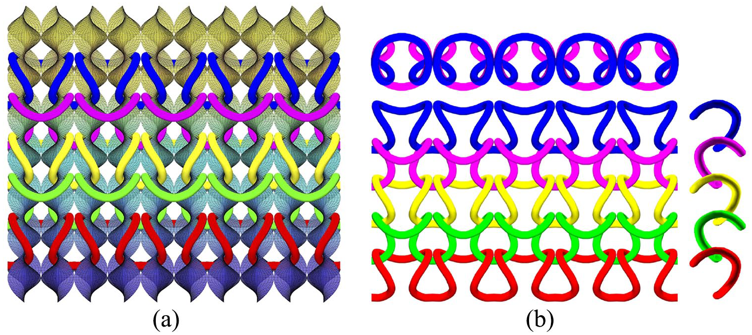
Geometric model of a garter fabric: (a) front view with helicoid scaffolding and (b) top, front, and side views without the helicoids.

Geometric model of fabric consisting of a random pattern of knit and purl stitches.
Changing model parameters
There are three parameters in our approach that can be used to control the shape and size of the loops in the modeled fabrics. They are the yarn radius

Effect of changing the yarn radius with respect to the helicoid radius, while keeping the helicoid’s height scaling factor constant: (a) Ry = 0.1, (b) Ry = 0.3, (c) Ry = 0.5, (d) Ry = 0.75, and (e) Ry = 1.0.

Effect of changing the helicoid radius while keeping the helicoid’s height scaling factor and the yarn radius constant: (a) Rh = 1.0, (b) Rh = 2.0, (c) Rh = 3.0, and (d) Rh = 4.0.

Effect of changing the helicoid’s height scaling factor while keeping the helicoid radius and yarn radius constant: (a)
Changing the yarn radius changes the distance of the yarn’s centerline from the helicoid surface. Changing the helicoid’s radius affects the width of the resulting stitches. Changing the helicoid’s height scale factor affects the height of the resulting stitches.
Conclusion and future work
In this article, we have presented the mathematics and algorithms needed to utilize the helicoid, a bicontinuous, minimal surface, as a scaffold for defining the topology and geometry of yarns in a weft-knitted fabric. The geometry of a half-loop of yarn is specified as a geodesic path along the surface with fixed boundary conditions. This optimized path may be duplicated, reflected, and shifted to produce the centerlines for the multiple stitches that make up a fabric. The geodesic path is produced via an optimization process which shortens the distance between the vertices that make up the yarn model, while keeping them a set distance from the helicoid surface. The yarn geometry is generated as a tube around the centerline. A second plane of reflected helicoids is utilized to define purl stitches, which then allows us to create models of not only all-knit fabrics but also rib and garter fabrics. Since the yarn geometry lies on the helicoid surfaces, changing the parameters of the helicoid (radius and height scaling) controls the size and shape of the stitches in the modeled fabrics.
The work presented here is a proof-of-concept that demonstrates the effectiveness of helicoid scaffolds for modeling weft-knitted fabrics. Our intent is to incorporate these models into a computer-aided design (CAD) system and to use them as input to physical simulations of knitted fabrics. We recognize that the current compute times needed to generate the models are not conducive for interactive design. Future work will focus on methods that speed up the calculations, for example, creating an implementation in a compiled language and investigating ways to increase parallelism.
Currently, we only model knit and purl stitches. In the future, we will incorporate other stitches into our modeling approach, for example, miss, tuck, and transfer stitches. Once these stitches are implemented, plans are being formulated for using helicoid scaffolds as a framework for simulating the weft knitting process and the knitted structures that it produces. In this future work, needles and the way they define the topological/geometric relationships between yarns will be represented with helicoid segments. Simulating the knitting process will involve transferring yarn loops between helicoid segments, similar to the actions of needles. The helicoid framework allows us to reproduce this mechanical process with a geometric computation, alleviating the need for a physical simulation in order to produce correct topological structures and plausible yarn geometries.
Finally, we note that our yarn models exhibit a curvature discontinuity when outside of the helicoid’s radius. We aim to address this issue in our future models.
Footnotes
Declaration of conflicting interests
The author(s) declared no potential conflicts of interest with respect to the research, authorship, and/or publication of this article.
Funding
The author(s) disclosed receipt of the following financial support for the research, authorship, and/or publication of this article: This material is based upon work supported by a National Science Foundation Graduate Research Fellowship under Grant No. DGE-10028090/DGE-1104459 and NSF grant CMMI #1537720. Any opinion, findings, and conclusions or recommendations expressed in this material are those of the authors(s) and do not necessarily reflect the views of the National Science Foundation. This work was supported in part by a Simons Investigator Grant from the Simons Foundation to R.D.K.