
Abstract
Processing carbon fiber reinforced thermoplastic parts includes heating to form the thermoplastic matrix. The needed heat can be applied externally or internally to the preform. One possibility to generate intrinsic heat involves the use of carbon fibers as a resistive element to induce joule heat. So far, most research efforts have been based on contacting continuous carbon fibers on both ends to melt the thermoplastic matrix of a pre-impregnated preform. The objective of this project is to use a dry hybrid yarn textile in a one-step process to impregnate and rapidly consolidate the dry textile in less than a minute. The desired molding process is based on joule heating of carbon fibers due to an applied current in the transverse fiber direction. This article focuses on the detection of the involved macroscopic parameters. The first composites produced by means of this new method exhibit a high potential with heating times of 15 s, a void fraction below 1%, and flexural properties comparable to the state of the art.
Introduction
Research and development of technologies in the field of fiber reinforced plastics show a tendency toward thermoplastic matrix materials due to their advantages in terms of the degree of automation, cycle times, and recyclability.1,2 The state of the art for working with thermoplastic matrix materials is based on sheets of pre-impregnated woven fibers.3,4 The processing of these materials includes the heating of the sheets as a primary stage to the forming process in an infrared (IR) oven with a subsequent injection molding process to functionalize the component. 4 However, with respect to processing times and energy consumption, there remains room for improvement. Literature states that the power efficiency of carbon fiber joule heating values is up to 90%.4,5 For heating a sample (25 × 150 × 0.5 mm3) from room temperature to 300°C, Koslowski et al. report an energy consumption of 0.02 kWh.
The development of hybrid yarns made of reinforcing and polymer fibers offers advantages for the processing of carbon fiber reinforced thermoplastic (CFRTP) materials. The resulting semifinished product could be a woven material enabling the production of a finished part in a one-step process. This can be achieved by using a single tool to drape the dry textile into its final shape, applying heat and pressure to the reinforcing fibers, and finally, consolidating the composite. The challenge for this procedure is the heating of the textile in an energy-efficient way.5,6
Joule heating of carbon fibers is a rapid method allowing for heating rates between 60 and 90 K/s. 5 Table 1 shows the history of using this phenomenon to produce carbon fiber composite parts. The presently applied joule heating method for carbon fiber composites is oriented along the fibers, thus making it difficult to ensure sufficient contact with all fibers, especially in the case of complex shapes.4,12 Therefore, a different setup is investigated in this article, which involves a tool applying current in the transverse fiber direction. Thus, a combined joule heating and molding process can be established. To develop an applicable joule heating technology, the corresponding parameters need to be detected and assessed. The pressure- and temperature-dependent material resistance during the process and the heat generation mechanisms (fiber heating through joule losses, dielectric hysteresis heating, and contact resistance heating between fibers) are known from the literature.14–16 Therefore, the experimental focus is based on macroscopic variables to prove the feasibility on a laboratory scale.
State of the art for joule heating in CFRP applications.

CFRP: carbon fiber reinforced plastic; NCF: non-crimp fabric.
Experimental procedure
As reinforcing fibers are impregnated and consolidated, different parameters affect the heating process between two electrodes of a conductive hybrid yarn textile. The applied pressure between both electrodes, the amount of current and voltage applied to the textile, the surface condition, the material and base temperature of the tool as well as the setup of the textile must be explored. The experiments carried out for the research presented in this article investigated these parameters by means of a material and experimental setup specifically adjusted to this technology.
Materials
Manufacturing new components based on recycled carbon fibers (rCF) gives advantages with respect to environment and cost. The obtained rCF can be classified into three categories, which are residues of production, prepreg fibers, and rCF from end-of-lifetime products. 17 The developed material for this article is based on a staple fiber yarn. This yarn contains PA6 fibers of 60 mm length (Radici) and rCF from residues of production, which are carbon filaments type SGL SIGRAFIL C T24-5.0/270 from bobbin ends that were machine-cut to 80 mm. At the end of the carding process, both reinforcement and matrix fibers are in the same length. Hengstermann et al. 17 described the development of the hybrid yarn. Manufacturing was done by Wagenfelder GmbH, Wagenfeld, Niedersachsen, Germany. A differential scanning calorimetry (DSC) analysis of the hybrid material gives a melting point of 222°C. The fiber density is 1.8 g/cm3 and the matrix density equals 1.14 g/cm3. The hybrid yarn was processed into a textile structure by means of weaving. For this purpose, an MAGEBA SL 1200/1 RTEC rapier shuttle loom in combination with a STÄUBLI LXLV jacquard machine was used (Figure 1). The machine and yarn setup were identical for all further discussed variants. The warp yarns were fed from the creel.
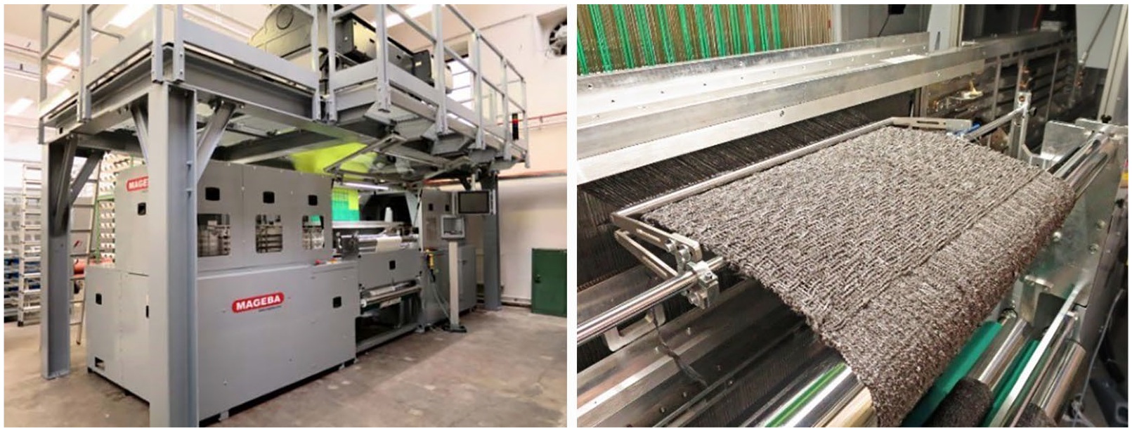
MAGEBA shuttle weaving loom (left) and sample production (right).
Five different variants were developed to investigate the influence of weave patterns on the heating process. These are based on the binding type Layer-to-Layer and differ in terms of the warp layers running on top of each other and the number of warp yarns simultaneously interlacing between the layers. The basic assumption is that the conductivity of the fabric can be adjusted by modifying its thickness and the proportion of interlacing warp threads as an important influencing factor on the consolidation process. The structure and binding of the generated variants are introduced in Table 2, whereby the warp interlacement between fabric layers is highlighted for better visibility. In addition, the binding type is shown in matrix notation according to the convention of Lomov/Gusakov.18,19
Fabric structure and pattern plots of V1–V5.

Experimental setup and test conditions
The experimental setup for the investigations is illustrated in Figure 2. The press is a construction installed by FIBRO GmbH and powered by a pneumatic bellow from Festo AG (EB-385-230). The resulting force generated by the bellow is at each pressure level a function of the working height as described in the data sheet. To control the pressure in the bellow, an electric pressure controller (EL-Press, Bronckhorst GmbH) is used. The press is equipped with a travel sensor (BTL7, Balluff GmbH) to measure the thickness of the textile. For tempering, two Regloplas 150S units are connected to a Regloplas Vario unit, which either cools or heats the tool. The tempering medium is RO200 oil. To achieve reproducible results, a DC current source built by TLU GmbH can supply 2000 A at 20 V. For closing of the electric circuit, direct current contactors (H60160, Crydom Inc.) are utilized. The temperature at the tool surface was constantly measured by 0.5-mm K-type mantle thermocouples (TCDirekt GmbH). A Graphtec logger GL240 was used to log voltage and temperature data during experiments.

Experimental setup of the molding process.
To understand the influencing parameters, different tools were defined. Table 3 gives an overview of these tools. The parameter analysis was mainly based on Tool 1. Tool 2 and Tool 3 were used to verify the tested parameters for different geometries. Figure 3 shows a graphical depiction of the concept of the tools. Each die consists of three parts, that is, a mounting part for electric isolation (made from polyoxymethylene), a plate holder for tempering and power transmission (cold work steel 1.2842), and an exchangeable plate (1.2842).
Used tool geometries for parameter analysis.

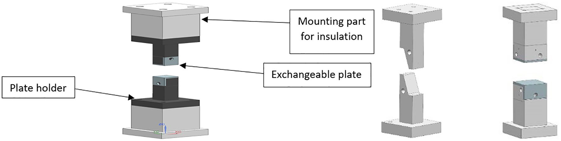
Tool 1 including insulating mounting part (left), Tool 3 (middle), Tool 2 (right).
The concept is to place a woven or nonwoven textile between the upper and lower electrode. Subsequently, pressure in the range from 5 to 25 bar, current in the range from 50 to 200 A at a maximum of 20 V, and tool temperature in the range from 100°C to 150°C are applied to explore the behavior of the textile. These parameters were also tested for different surface conditions of the exchangeable plates. Experiments were carried out with polished, grinded, and coated surfaces. Coating was applied to a grinded surface consisting of two layers of sealer and release agent. In a first step, the sealer Loctite Frekote 770NC was applied, and in a second step, the mold release agent Loctite B15 was added. All tests were performed in a shop floor hall at approx. 23°C. To process the material in the experimental setup, textiles were conditioned at 80°C for 1 h.
The results gained from the parameter analysis performed with Tool 1 are verified on an increased scale. Hence, these parameters were used to conduct experiments with Tool 2 and Tool 3 to test shapes that are potentially suitable for larger tools to consolidate complex three-dimensional (3D) parts. The process was investigated for the established parameters with respect to an increased contact area of Tool 2 and Tool 3 from 900 to 1800 and 2500 mm2. It was evaluated whether there is a global current density at which the process works in addition to observing its continuity by comparing the results from different tools.
The dimensions of Tool 1 and Tool 2 match by a factor, which is why only Tool 1 and Tool 3 are illustrated in Figure 4. On the left of Figure 4, one can see the plate holder with the heating–cooling channel as well as the exchangeable plate with the 0.55 mm bore for the mantle thermocouple. The 2 mm bore at an 45° angle depicts the inlet for the thermocouple. On the right, Tool 3 with the 20° surface is presented. The position of the thermocouple and the heating–cooling channel can be seen as well.
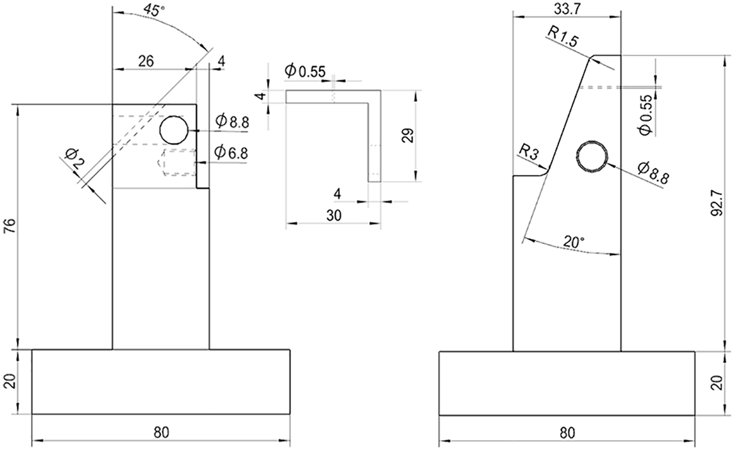
Dimensions of Tool 1 (left) and Tool 3 (right).
During experiments, the 0.5-mm mantle thermocouple type K was used on each side in the middle of the exchangeable plate as presented in Figures 4 and 5 for continuous temperature monitoring. The thermocouple is guided through the diagonal hole and then placed into the 0.55 mm hole in the exchangeable plate. The thermocouple is fabricated such that the temperature measurement is not affected during current flow (TCDirekt GmbH).

Exchangeable plate (left) and size of one sample as used for Tool 1 (right).
In addition, Figure 5 (left) shows an actual exchangeable plate with a hole for the thermocouple in the center. The picture on the right displays the woven multilayer fabric developed at the Institute of Textile Machinery and High Performance Material Technology, Dresden, Germany, in the form of a cut sample as used in the experiments. When placing the tool into the press, the orientation of upper and lower die was controlled by spotting the die for even contact. The current was applied to the tool by screwing a cable to the exchangeable plate by means of the same screw employed for connecting the plate to the plate holder. This leads to the establishment of the electric circuit described in Figure 6.
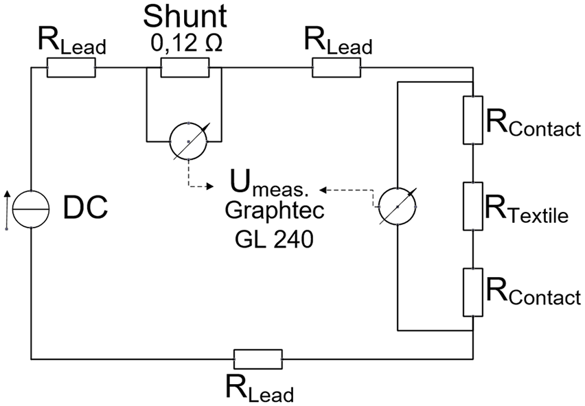
Electric circuit and points of measurement.
The electric circuit is adequate to all examined tools. Starting from the DC current source, losses occur in every wire, which are characterized by the resistances RLead. The voltage drop across the two contact resistances RContact and the resistance of the textile RTextile is measured at a sampling rate of 100 ms using the Graphtec logger GL240. The shunt has a defined resistance of 0.12 Ω, so the applied current can be calculated from the voltage drop across the shunt. Since it is difficult to measure the contact resistance between textile and tool and the heating behavior depends significantly on the surface conditions of the tool, 5 the relevant resistance for the process will be stated in this article as a combination of two contact resistances plus the actual resistance of the textile.
Experimental results and discussion
Influence of the textile construction on the heating behavior
The multilayer fabrics described in Table 2 vary in terms of their number of layers and tyings. These parameters affect the material resistance and increase the risk for defects during the heating process. These defects can best be described as an electric burn and are caused by inhomogeneous current flow through the textile. Figure 7 depicts the differences in the temperature development of the five textiles. Materials V1 and V2 are two-layer textiles, whereas materials V3, V4, and V5 are three-layer textiles. These five different types were all subjected to an identical pressure of 22 bar relative to the surface area and an identical mold temperature of 100°C. The surface of the exchangeable plates was coated. The currents selected for testing were 50, 80, 110, 140, and 170 A. The corresponding current source compensated the changing voltage drop across the textiles while constantly applying the preset amount of current. As soon as a defect occurred, experiments for that particular material were stopped as the critical current density had been reached. For each material and each current, five probes were conducted.
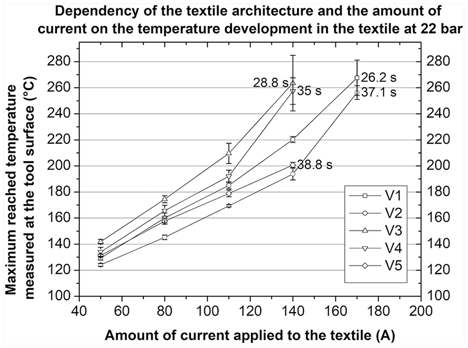
Results regarding the dependency between textile structures and heating behavior with the respective time to reach the asymptotic solution.
Experimental results are presented in Figure 7. The y-axis illustrates the maximum mean temperature measured in the upper and lower die reached in the textile in relation to the amount of current applied (x-axis). Based on Figure 7, it can be concluded that materials V2 and V5 reach the lowest temperatures, followed by V1. Materials V3 and V4 achieve the highest temperatures at the lowest current. Materials V3 and V4 were sufficiently consolidated at 140 A, while materials V1 and V2 required 170 A for proper consolidation, and material V5 developed defects prior to reaching a satisfying state of consolidation. This suggests that thinner materials need a higher amount of current for consolidation compared to thicker materials. This can be explained following Ohm’s law. A thinner textile has a lower resistivity and therefore needs a higher current to dissipate the same amount of heat as a textile with a higher resistivity. It can also be seen that the weaving pattern has an influence on the heating behavior. The more homogeneous the textile is with respect to the current flow in transverse section, the higher the reached temperature. Material V3 is chosen for further experiments due to its homogeneous heating behavior at high temperatures.
Influence of the surface condition on the heating behavior
The influence of the tool surface condition on the temperature development was examined as well. The results can be seen in Figure 8. In a first step, surface roughness was determined by a roughness tester Mitutoyo SJ-210. The grinded surface was created with a surface grinding machine, the polished surface was manually achieved, and the coated surface was created by manually applying two layers of sealer and two layers of release agent to a grinded surface. The exchangeable plates were then tested with material V3 at currents of 50, 80, 110, 140, and 170 A and a tool temperature of 100°C. For each surface condition and current, five probes were conducted.

Degree of roughness of different surfaces (left) and dependency of achieved temperatures on surface condition with the respective time to reach the asymptotic solution (right).
The graph on the left in Figure 8 presents the Rz and Ra value for each surface condition, whereas the graph on the right displays the maximum reached mean temperatures measured in the upper and lower die for the different surfaces. It is revealed that the surface condition of the tool has a significant impact on the heating behavior of the textile. A reason may lie in the changing contact resistance between tool and textile. The larger the contact area of the textile with the tool, the smaller the resistance. This means that the grinded surface has the lowest overall resistance due to high Rz and Ra values. Figure 8 shows that the grinded surface leads to the lowest achieved temperatures. Only the polished and coated tool surfaces generated sufficiently consolidated probes during the experiments. At 170 A, the increased contact resistance due to the polished tool surface leads to sufficient consolidation, whereas the coated surface reaches significantly higher temperatures even at lower currents. As a result, in terms of this concept, increasing the contact resistance by using coated surfaces leads to an enhanced heating behavior at a lower current. An explanation is given by Zantout et al. They describe in addition to the joule heating mechanism of the textile a dominance of contact resistance heating at high temperatures. 15 This is a main difference in contrast to other concepts of joule heating that typically try to minimize the contact resistance between textile and tool to ensure a low temperature gradient along the fibers. 5 A coated tool surface is therefore recommended.
Sensitivity of resistance to pressure and influence on heating behavior
The resistance of the multilayer fabric shows a high sensitivity to pressure, which is due to the condition of the textile. If it is compressed, more conductive carbon fibers are in contact, and the resistance decreases. Figure 9 shows the settling behavior of the five different textiles over time at pressures ranging from 5 to 25 bar. The mold temperature was 100°C. For each pressure level, five probes of each textile were conducted. The displayed resistance was calculated based on a four-terminal sensing measurement in the style of DIN EN 16812 using Tool 1.

Dependency of resistance to pressure.
Figure 9 reveals that the resistance of each textile is reduced significantly with higher pressure. It additionally reveals that the settling time until the textile reaches a constant resistance is lowered with increasing pressure and that the different materials do not show a constant relationship. The top diagram in Figure 9 illustrates that the resistance of the material continues to change after 2 min, while the diagrams in the middle and on the bottom show that the material exhibits a nearly constant behavior after 60 s. The decreasing resistance can be explained by the negative temperature coefficient (NTC) behavior of the carbon fibers and the settlement of all fibers in the dry textile. 20 Tests of the consolidation behavior at different pressure levels prove that a pressure of 22 bar yields the best optically evaluated consolidation for material V3 at the lowest current level. On the y-axis, Figure 10 (left) depicts the mean maximum temperature measured at the tool surface of upper and lower die. The x-axis shows the different pressure levels at which the current of 140 A was applied to the textile. With increasing pressure, the standard deviation and the final temperature reach a minimum. It can be stated that the higher the pressure, the higher the needed amount of current to achieve the same temperature level.

Heating behavior at changing pressure levels with the respective time to reach the asymptotic solution (left), evolution of specimen thickness during current flow at 30 bar (right).
Figure 10 (right) exhibits the evolution of specimen thickness for a pressure of 30 bar and 175 A. The diagram depicts a significant difference between the thickness of a compressed, not consolidated textile at room temperature and a compressed textile heated to over 250°C. During the impregnation process, the polymer melts and the air is being pressed out. This leaves a structure of discontinuous carbon fibers giving the final dimensions with respect to thickness. The standard deviation of the thickness at approx. 250°C shows the inhomogeneity of the multilayer fabric manufactured at lab scale during a research project.
Influence of the mold temperature on the achieved temperatures
The temperature of the tool has a significant influence on the maximum reached temperature measured at the tool surface. Figure 11 shows the maximum mean temperature achieved in textile V3 in dependence on the mold temperature. The settings for the current feed were kept constant at 22 bar and 130 A, and only the mold temperature was set to 110°C, 120°C, 130°C, 140°C, and 150°C. The examined material was V3, the surface was grinded, and for each mold temperature, five probes were conducted.

Dependency of maximum reached temperature on mold temperature with the respective time to reach the asymptotic solution.
Figure 11 illustrates that the maximum reached mean temperature in the textile varies between 190°C and 220°C, depending on mold temperature. In conclusion, the mold temperature is a decisive factor determining process time and stability; this will need to be adapted to different matrix materials. All illustrated values in Figure 11 deviate within a similar range. For material V3, a mold temperature of 130°C was selected for a stable process.
Process cycle and stability
To ensure that the values obtained from the parameter analysis are statistically valid, the impregnation and consolidation process was carried out 30 times with identical settings at 140 A, 22 bar, and a mold temperature of 130°C. No defects occurred during this test. Based on the determined relation between temperature and time, approximate values for the heating time to reach the melting point of the hybrid yarn material at 222°C can be derived (Figure 12, right).

Heating behavior—single values for anode / cathode (left) and arithmetic average (right).
Figure 12 presents the curves for the mean temperature progress measured at the tool surface in the upper and lower die of the textile over time. The current was selected so that the textile temperature always remained lower than the PA6 degradation temperature. The diagram shows an asymptotic solution at 240°C. Since the tool was constantly tempered at 130°C, it automatically cooled the textile at the transition area between tool and textile. Hence, the impregnation process started in the middle of the textile, and as soon as the temperature reached 222°C in the transition area, the matrix material was completely melted. These diagrams can be used to determine the approximated heating time until one part is impregnated and consolidated. This is the case after approximately 15 s. The time to reach 222°C matches the findings in other publications,3,12 where probes of pre-impregnated thermoplastic sheets were heated along the fiber orientation using joule heating. If the textile is placed into the tool at ambient temperature, the resulting heating rate corresponds to 13.3 K/s.
The diagram on the left shows the individual values of the temperature measured in the anode and in the cathode, whereas the diagram on the right shows the arithmetic average of both values. The temperature difference between anode and cathode is revealed by the collected data and can be verified by optical inspection of the probes. An explanation for this phenomenon is the Peltier effect. 21 Since steel and carbon have a large difference in the galvanic series, 22 the transition from steel to carbon leads to the emergence of Peltier heat, and the transition from carbon to steel leads to the use of Peltier heat. This effect is dependent on the current. 23 The higher the current, the larger the difference between anode and cathode.
The appearance of this effect is further demonstrated in Figure 13. To verify whether the effect is based on a thermoelectric context, the direction of the DC current was changed by manually switching the attached cables at the upper and lower die. For each direction of the current, five samples were examined at constant settings of 140 A, 22 bar, and 100°C tool temperature. Figure 13 depicts that by changing anode and cathode, either the upper die reaches a higher temperature or the lower die reaches a higher temperature.

Influence of thermoelectric effect on the heating process.
Quality of the consolidated material and effect of a vacuum
To determine the quality of the consolidated material, different tests were performed using probes which were consolidated by joule heating under vacuum and atmospheric conditions as well as a standard hot press method under vacuum. The material selected was V3. All samples were produced with an identical pressure of 22 bar and the edges were cut. To assess the quality of the joule heating samples, a three-point flexural test and a void analysis were performed (Figure 15). The flexural test was carried out in agreement with DIN EN ISO 178 and the void analysis following DIN EN 2564; the employed technique was based on a gray scale analysis on a grinding pattern and a wet chemical calcination with a cut sample. An analyzed micrograph section can be seen in Figure 14. For analyzing purposes, each of the three grinding patterns from the middle of different samples was evaluated to determine the percentage of voids using gray scale analysis. To verify the achieved results, wet chemical calcination was performed for all samples.

3D micrograph section of consolidated material (Keyence VHX-6020).
Figure 14 shows a 3D image of a grinding pattern. It can be seen that the elevation profile at the marked line in the upper right picture gives a maximum difference of around 3 µm. This cannot be considered as a void. Therefore, black spots with a diameter smaller than the minimum fiber diameter (6 µm) in the micrograph do not need to be considered for gray scale analysis. The gray scale analysis was carried out using the software “Olympus Stream Essentials.” The software assigns gray values to different phases on the basis of a comparative image and then counts the respective area fraction. The microscope used is a Carl Zeiss axiotech vario 100HD with an Olympus DP74 tube at 50× to 100× magnification.
The void content measurement in Figure 15 (left) suggests that the results of both analysis methods lead to comparable results. Thus, it can be concluded that samples produced by joule heating without vacuum possess voids at a percentage of approx. 3%, samples generated by joule heating with vacuum have a percentage of voids of approx 1%, and samples produced by use of hot press heating with vacuum exhibit less than 1% voids. By examining the grinding patterns from the middle of each sample, it can also be stated that no dry fibers could be found. In summary, the joule heating method yields results that are almost identical with the state of the art. Figure 15 (right) reveals the results of the flexural tests. The joule heating samples (manufactured under vacuum) give a significantly larger standard deviation at a comparable level to the state of the art.

Void content measurement (left) and flexural strength measurement (right).
Regarding the quality of the consolidated material with respect to lateral displacement of fibers in the plane of the plates, an advantage of the discontinuous yarn, woven to a multilayer fabric, against a standard twill binding using continuous filaments was noticed. While the authors performed tests using this new technology on various woven and nonwoven textiles, it is worth mentioning that fabrics based on discontinuous fibers showed no noticeable lateral displacement, while, especially, continuously reinforced twill bindings showed an outward displacement of fibers from the center of the tool.
Testing different tools to verify established parameters
The three differently shaped tools that were used during parameter analysis (Table 3, Figure 3) showed a predictable behavior regarding the heating behavior and consolidation quality. Figure 16 illustrates a sample of each tool. The parameters determined by means of the tool with the flat 900 mm2 surface could be transferred to the tool with the flat 2500 mm2 surface as well as to the 20° inclined surface tool.

Comparison of uncut consolidated specimens from different tools.
Based on Figure 7 and optical inspection, a current of 140 A was the optimal setting for the 900 mm2 surface without defects occurring in the consolidated material, that is equivalent to a current density of 0.156 A/mm2. Identical tests as described for the 900 mm2 surface were performed with the 2500 mm2 surface using material V3. A current of 380 A was sufficient to reach equivalent optical results. The resulting current density is 0.152 A/mm2. The current required for the 20° inclined tool is 280 A, which equates to 0.156 A/mm2. A comparison of the different values leads to the assumption that for the selected settings in terms of pressure, surface condition, material and temperature of the tool and textile construction, a global current density exists to impregnate and consolidate carbon fiber hybrid yarn textiles.
Conclusion
The obtained results prove that the developed technology has a high potential toward the efficient and productive manufacturing of CFRTP parts. Several advantages were detected compared to the state of the art in the production of CFRTPs. One aspect is the short heating time of 15 s, which allows the completion of the impregnation and consolidation process in less than a minute. Another advantage is the volumetric heating of the textile with a low thermal gradient in the transverse section. This is especially interesting for polymers with a high melting point like PEEK (polyether ether ketone), PPS (polyphenylene sulfide), or PPA (polyphthalamide). Furthermore, the intrinsic heating method provides an energy-efficient process for thermoplastic composites and the possibility of manufacturing complex component geometries.
Thus, the technology developed within the project is a first step toward developing a new tooling concept to rapidly consolidate textiles with carbon fibers based on thermoplastic yarn. With respect to the automotive industry, this technology might lead to an increased adoption of CFRTP parts due to shorter process times and enhanced energy efficiency.
Perspective
A perspective to the applicability of the technique to large samples bears uncertainties with respect to biased electric currents due to inhomogeneities of the textile or the compression ratio. The authors work on a solution using multiple electrodes that are isolated from each other to form a tool with a complex shape. 24
Footnotes
Declaration of conflicting interests
The author(s) declared no potential conflicts of interest with respect to the research, authorship, and/or publication of this article.
Funding
The authors disclosed receipt of the following financial support for the research, authorship, and/or publication of this article: This research and development project is funded by the Federal Ministry of Education and Research (BMBF) under the concept “Innovations for the Production, Service and Work of Tomorrow” with funding from the Energy and Climate Fund (support code 02P14Z020 - 02P14Z030), managed by the Project Management Karlsruhe (PTKA). The authors are responsible for the content of the publication.