
Abstract
Three-dimensional mesh fabric is a special type of knitted spacer fabric with sandwich structure consisting of two separate meshed multifilament outer layers linked together with a layer of spacer monofilaments. It has found wide applications in home textiles and automotive industry due to its good energy-absorbing performance and ventilation property. This article presents a comprehensive structural analysis on a mesh spacer fabric of thickness 10.3 mm in order to place a solid foundation to enhance the understanding of the structural features and mechanical behavior. The real geometric structure was reconstructed by scanning the fabric via Micro X-ray computed tomography. The spacer monofilaments and meshed outer layers were analyzed quantitatively based on the Micro X-ray computed tomography reconstruction. It was found that the spacer monofilaments are different in length, curvature, and torsion. The spacer monofilament lengths can be ranging from 9.43 to 10.77 mm. Their curvatures varied from around 0.1 to 0.3 mm−1. The torsions of spacer monofilaments can be positive and negative with different directions of twisting and had a certain degree of symmetry between two adjacent wales. The monofilament loops in the outer layers also varied in height, width, and enclosed area. Three-dimensional mesh fabric is a periodic but highly inhomogeneous structure.
Introduction
Warp-knitted spacer fabric is a three-dimensional (3D) integral structure consisting of two outer fabric layers, which are kept apart but connected by vertical spacer monofilaments. 1 3D mesh fabric is a special type of warp-knitted spacer fabric whose outer layers are meshed.2,3 The distance or space formed by the two meshed outer layers filled with air and countless compression-resistant monofilaments enables the fabric to have several functions like mechanical cushioning,1,3,4 redistribution of compression pressure, 5 and air/moisture permeability. 6 In view of these functions, 3D mesh fabrics have found wide applications to take advantage of the designable compressibility and permeability. They have been used as cushioning materials without compromising in comfort for replacing polymeric foams in the development of automotive interior, cushion pads, mattresses, impact protectors, and so on. Compressibility and permeability are the two key factors concerned with those applications, and they are determined by the structural features of 3D mesh fabrics. 2
Attempts have been made to create geometric models at yarn level to simulate different warp-knitted spacer fabrics. Kyosev 7 proposed common strategies for multiscale modeling of textiles, concentrating on the yarn and filament levels. Following these strategies, Renkens and Kyosev 8 developed a principle for creating the geometry of spacer structures without mesh based on an emulation of the real knitting process, knitting on a flat machine first and then transforming the loops to their proper places in the 3D space. They also extended this method to simulate 3D jacquard warp-knitted structures. 9 Zhang et al. 10 empirically simulated the geometric structure of a 3D mesh fabric using Non-uniform rational basis spline (NURBS) curves. The geometric models created in the above studies were uniform, in which the geometries of spacer yarns are identical and inauthentic because realistic geometries were not considered.
The mechanical behavior of warp-knitted spacer fabrics has been studied experimentally and theoretically. Liu et al.1–4 examined the effects of the spacer yarn inclination angle and fineness, fabric thickness, and outer-layer structure on the compression stress–strain relationships of warp-knitted spacer fabrics with and without meshes under static and impact loadings. Although the spacer yarn inclination angle has received considerable attention in previous studies, the geometries of spacer yarns have not been focused and quantitatively discussed. Apart from experimental studies, some efforts have already been made to analytically or numerically study the compression deformation behavior of a spacer monofilament for providing an efficient way to predict the compression characteristic of spacer fabrics. Mokhtari et al. 11 proposed an analytical model for a single spacer monofilament, which was assumed to have a constant curvature along its length during compression. Chen et al. 12 additionally introduced the contact between spacer monofilament and fabric outer layer based on Mokhtari’s model. However, both Mokhtari’s model and Chen’s model ignored the fact that spacer monofilaments undertook postbuckling rather than pure bending. Helbig 13 reported an approximate explicit model for a spacer monofilament based on the force and moment equilibrium, but the real spacer yarn shape was not considered. Supeł and Mikołajczyk established two models by treating a spacer monofilament as an initial straight slender elastic rod using the Euler–Bernoulli beam theory in small deflection with either pinned–pinned or fixed–fixed boundary conditions.14,15 Later, they revised the model by using the large deflection theory and considered the spacer monofilament as an elastica. 16 Vassiliadis et al. 17 reported a finite element (FE) model to simulate the postbuckling deformation of spacer monofilaments. Brisa et al. 18 presented an FE model for a vertical spacer monofilament of a thick spacer fabric under compression by taking the contacts between the spacer monofilament and the outer layers into account during the compression process. Sun et al. 19 presented a parametric FE study on a spacer fabric by simplifying the spacer yarns as identical, vertical, and linearly elastic rods and adjusting the structural parameters to investigate the structure–property relationship. For the theoretical studies mentioned above, realistic geometries of spacer fabrics were not employed in the calculation or simulation, which considerably reduces the validity and significance of the models.
Hou et al.20,21 conducted an FE study on a spacer fabric with closed outer layers. In their study, the geometric shapes of the spacer monofilaments were calculated by a nonlinear buckling analysis from the manufacturing parameters, and the outer layers were modeled as two isotropic planes. Liu and Hu 22 also reported an FE study on the compression behavior of a typical spacer fabric structure with closed outer layers based on the precise geometry of a unit cell reconstructed from Micro X-ray computed tomography (μCT) scanning by fully considering the yarn interactions among all the fabric components and the material’s nonlinearity, thereby achieving a satisfactory prediction of the compression load–displacement relationship of the fabric. The geometries of spacer monofilaments were acquired by either indirect postbuckling analysis in physical sense or direct μCT scanning. However, the acquired geometries were not quantitatively analyzed in the previous studies, and the obtained geometries were for warp-knitted spacer fabrics with closed outer layers. The formation of 3D mesh fabrics is quite different from the fabrics without mesh. The meshes are not only affected by knit patterns but also mainly formed by stretching in the heat-setting process. The stretching process makes the outer layers change from fine mesh to coarse mesh. In this process, the geometries of spacer monofilaments and monofilament loops in the outer layers are significantly deformed.
The mechanical and ventilation properties of 3D mesh fabrics are determined by the fiber architectures. However, little attention has been paid to the exact geometries of the fabric structure. A thorough understanding of the precise fabric geometric structure is vital for predicting the mechanical behavior and also developing 3D mesh fabrics for a specific application. This work is aimed at providing a deeper insight into the structural features of a typical 3D mesh fabric by obtaining the exact geometry via μCT scanning and quantitatively analyzing the spacer monofilament length, curvature, and torsion, as well as the monofilament loop shapes in the meshed outer layers. The findings obtained could provide an accurate geometric model for further numerical studies and also enhance the understanding on how spacer monofilaments change in the heat-setting process.
Formation of 3D mesh fabric
A warp-knitted spacer fabric with coarse meshed outer layers was knitted on an RD6 double-bar raschel machine built by KARL MAYER Holding GmbH & Co. KG in Germany for producing coarse spacer textiles. The machine is equipped with two needle beds, six yarn guide bars, and a machine gauge of E12. The two meshed outer layers were knitted with four sets of 600D/192F polyester multifilaments. While the top outer layer was knitted with GB1 and GB2, the bottom outer layer was knitted with GB5 and GB6. Another set of polyester monofilaments of diameter 0.22 mm was knitted with GB3 to connect the two outer layers in a single knitting process. The chain notations and yarn materials used are given in Table 1.
Chain notations and yarn materials used for the 3D mesh fabric.

After the knitting process, the spacer fabric was taken from the knitting machine in a closed form, following by a heat-setting treatment at 200°C for 30 s to enhance the structural stability and to achieve a required meshed form. The specifications of the resultant mesh fabric are listed in Table 2. In order to have a clear view on the formation process of the mesh fabric, the closed form after removal from the machine and the meshed form after stretching in the heat-setting process were simulated by using the software EAT ProCad Warpknit, as illustrated in Figure 1. The fabric off machine is around 12 wales/inch (4.72 wales/cm), and it was stretched to 7 wales/inch (2.75 wales/cm) in the heat-setting process. The width of the mesh fabric is nearly twice of its initial width. At the same time, the length and thickness of the fabric decreased. The chains formed by GB2 and GB5 are almost straight and perfectly opposite initially, as shown in Figure 1(a) and (c). Each pair of the chains is connected by a single monofilament which forms the spacer monofilaments. In this initial state, the meshes are not evident. After stretching in the coursewise direction and heat setting, the chains of the mesh fabric become sinusoid, thereby forming coarse meshes. For this particular mesh fabric, the chains in the top layer and bottom layer are no longer completely opposite, and their phase difference is around 180 degrees. This is because the inlay yarns formed by GB1 and GB6 are offset intentionally to obtain a stable structure. As the chains in the top and bottom layers deform in the opposite directions, the spacer monofilaments connecting them are twisted, as illustrated in Figure 1(b) and (d).
Specifications of the 3D mesh fabric.


Stretching spacer fabric to form coarse mesh: (a) top view of the initial state, (b) top view of the mesh state, (c) isometric view of the initial state, and (d) isometric view of the mesh state.
Photographs taken from the 3D mesh fabric in walewise and coursewise directions, outer surface, and internal surface are shown in Figure 2. As expected in the simulation, the spacer monofilaments are highly torsional to connect the offset pair of chains (Figure 2(a)). In the length direction, the monofilament is continuous and the geometries of spacer monofilaments vary from one to another (Figure 2(b)). It is notable from the outer and internal surfaces of the fabric (Figure 2(c) and (d)) that the spacer monofilaments are almost entirely covered by the fluffy multifilaments and that the spacer monofilaments are constrained by the tight loop formation of the multifilament stitches, which provides great stability to the fabric. Chains connected by inlay yarns form the side limbs, and the remaining chains without connection form the meshes. The meshes formed on the outer layers are periodic and similar. Side limbs in one layer are almost located at the center of the respective meshes in the other outer layer. In this way, most of the spacer monofilaments are arranged in an inclined form, and the spacer monofilaments of two adjacent wales are symmetrical to some extent (Figure 2(c)). This symmetry further enhances the structural stability of the 3D mesh fabric subjected to compression. It is found that the geometric variations of spacer monofilaments of 3D mesh fabrics are much greater than those of spacer fabrics with closed outer layers. 22

Photos of 3D mesh fabric: (a) side view from walewise, (b) side view from coursewise, (c) outer surface, and (d) inner surface.
μCT scanning and reconstruction
A μCT scan of the mesh fabric was conducted to create from the obtained slices a precise 3D reconstruction. A fabric sample of size 2.5 cm × 0.8 cm enclosed in a plastic tube was scanned along the fabric length direction by using a μCT system VivaCT 40 built by SCANCO Medical AG in Switzerland. The scanning parameters set for the scanning were as follows: spot size: 5 μm, 50–70 kVp, and 160 μA.
The 3D μCT reconstruction of the mesh fabric with two wales in its initial stress-free state is shown in Figure 3. It could be clearly seen that the spacer monofilaments and monofilament overlaps in the outer layers are well and accurately reconstructed. In contrast to the monofilaments, the multifilament loops in the outer layers are not well reconstructed due to resolution limitations of the μCT system. For this reason, the 3D geometry cannot be directly meshed and implied into the FE software for further mechanical simulation. It is important to note that the spacer monofilaments are the main load carrier during compression, whereas the outer layers do not deform significantly during compression and function more as a boundary layer. In this connection, the exact geometry of monofilaments is more important than that of multifilaments.

3D μCT reconstruction of the mesh fabric from different viewpoints: (a) isometric, (b) outer layer, (c) side view from walewise, and (d) side view from coursewise.
The monofilament architecture is presented in Figure 3 by filtering out the multifilament yarns. It can be seen that each wale was formed by a continuous monofilament. The monofilament was knitted on two needle beds to create the entangled overlaps and swung between the two beds to form the spacer monofilaments. Each monofilament wale is an integral structure, but adjacent monofilament wales are separate and connected by multifilament inlay yarns. Since monofilaments are entangled within the outer layers and the spatial shapes of the loops are not identical, an irregular outer-layer thickness is observed. By neglecting the multifilament thickness, it varies between 0.22 and 0.44 mm at the interloop point, which equals the diameter of one or two monofilaments.
In order to conduct a quantitative analysis on the spacer monofilaments and monofilament loops, it is necessary to differentiate the spacer layer from the two outer layers. A split layer is defined in Figure 3(c) and (d) to separate the spacer layer from the outer layers so that the spacer fabric can be divided into three parts: a spacer layer and two outer layers. Since the spacer fabric is a periodic structure, a unit cell as annotated in Figure 3(b) is considered for this study because it is the smallest element of the fabric including all geometric features. The spacer monofilaments of the unit cell were digitalized by image processing to get their exact 3D coordinates for further calculation, while the structural parameters of the outer layers were measured directly on the divided μCT reconstruction for the top and bottom outer layers.
Since the fabric sample was initially scanned along its length due to the limitation of the system, it is necessary to slice the μCT reconstruction in a second step through its thickness. The reconstruction was sliced into 42 slices, and each slice has a thickness of 0.26 mm. Slicing was carried out from a start height of 0 mm to an end height of 10.66 mm. This range includes the spacer fabric thickness of 10.3 mm, which was manually measured with a digital thickness tester (SDL Atlas M034e). The first four sliced images and the last four sliced images were not used for image processing because those slices belong to the outer layers defined by the split layer. Figure 4 presents a sliced image, which shows the cross section of the spacer monofilaments as well as a unit cell highlighted by a parallelogram. From the slice, it becomes obvious that a unit cell consists of 40 spacer monofilaments, 20 for each wale.

Sliced image with a highlighted unit cell.
An image processing algorithm was developed to automatically identify the spot centroids of the slices. The pixel size of the image is 0.021 mm, and the thickness of each slice is 0.26 mm. Therefore, the exact coordinates for all the spacer monofilaments of the unit cell can be calculated. The centroid provides exact information on the dimension, shape, and relative position of the respective spacer monofilament, so the unit cell spacer layer can be accurately created as shown in Figure 5. The thickness of the spacer layer is 8.41 mm. The numbers of the 40 spacer monofilaments are defined in Figure 5(b). Here, spacer monofilaments from 1 to 20 belong to the first wale (w1) and those from 21 to 40 belong to the second wale (w2). It can be observed that spacer monofilaments of the two wales are completely separate and are not that symmetrical. The spacer monofilaments are of great geometric variation. They are different in shape from one to another. Most of them are highly torsional and curved. Geometric calculations were conducted on these spatial shapes to quantitatively assess their geometric features.

3D unit cell spacer layer from different viewpoints: (a) isometric, (b) Y–X, (c) Z–X, and (d) Z–Y.
Structural analysis
Length of spacer monofilament
The spacer monofilament lengths were calculated based on their 3D coordinates, and the results are listed in Table 3. The lengths of the shortest and longest spacer monofilaments are 9.39 and 10.77 mm, respectively. As the thickness of the fabric is 10.30 mm, a difference of 1.38 mm between the two spacer monofilaments is considered to be significant. There is also a difference of 0.32 mm in the average length of the spacer monofilaments between the two wales in the unit cell. This implicates that the two wales consumed different amounts of monofilaments to form the spacer monofilaments in one repeat. It is considered that the spacer monofilament length mainly depends on the distance of two needle beds, knitting sequence, spacer yarn arrangement, yarn mechanical property, and individual yarn tension in the warping process. On one hand, for this particular 3D mesh fabric, the chain notation for all the spacer monofilaments was 1-0-0-1//, which is an open-pillar lap. On the other hand, monofilaments were feeding to the knitting mechanism at a constant speed during the knitting process. From this point of view, the yarn consumption for all the spacer monofilaments was the same and they should have the same length. The discrepancies in length might be due to the fact that tensions of the monofilaments wound on the beam were not identical. This uneven yarn tension could affect the monofilament supply in knitting the spacer monofilaments, thereby leading to different lengths. Another more important reason is that the stretching in the heat-setting process could change the shapes and lengths of the monofilament loops in the outer layers. The increase or decrease in the length of the monofilament loop will decrease or increase the length of the spacer monofilament, respectively.
Lengths of the spacer monofilaments.

Therefore, the consumptions of monofilament in different wales are similar, but its distribution in spacer monofilament and monofilament loop is complex. To obtain a 3D mesh fabric with uniform and evenly distributed spacer monofilaments, the monofilament tensions in the warping process should be carefully controlled to minimize the tension difference and the fabric should be evenly stretched in the heat-setting process.
Curvature and torsion of spacer monofilament
It is apparent from Figure 5 that the spacer monofilaments have different curvatures and torsions. The complex two-step formation process of 3D mesh fabric gave spacer monofilaments diverse curvatures and torsions, which were calculated numerically and are shown in Figures 6 and 7, respectively. Five curves are plotted in each panel of these figures for better presentation.

Curvatures of spacer monofilaments in the unit cell: (a) 1-5, (b) 6-10, (c) 11-15, (d) 16-20, (e) 21-25, (f) 26-30, (g) 31-35, (h) 36-40.

Torsions of spacer monofilaments in the unit cell: (a) 1-5, (b) 6-10, (c) 11-15, (d) 16-20, (e) 21-25, (f) 26-30, (g) 31-35, (h) 36-40.
Figure 6 shows that the curvature curves differ markedly with a low degree of regularity, and the curvatures normally vary from around 0.1 to 0.3 mm−1 with the fabric thickness. There is also no clear symmetry in curvature between the respective spacer monofilaments in the two wales. These indicate that the spacer monofilaments are highly nonlinear in terms of curvature.
The torsion curves in Figure 7, which are different from one to another, are also highly nonlinear. The torsion can be either positive or negative, indicating different directions of twisting. Some symmetries in torsion between the spacer monofilaments in the two adjacent wales can be observed. For instance, the spacer monofilaments 6–15 in the first wale w1 have negative torsions, whereas the corresponding ones 26–35 in the second wale w2 have positive torsions. This implicates that the two groups of spacer monofilaments are twisted in opposite directions. This result is consistent with the observation in Figures 2 and 3.
The statistic results for curvatures and torsions of the spacer monofilaments are listed in Tables 4 and 5, respectively. It is noteworthy to point out that there is a certain relationship between spacer monofilament length and curvature. A longer spacer monofilament tends to have a higher curvature and vice versa. The same relationship could also be found between spacer monofilament length and torsion. For instance, the shortest spacer monofilament 6 (Figure 5(b)) in w1 has a length of 9.39 mm, with its curvature varying from 0.126 to 0.220 mm−1 and the torsion changing from −0.004 to 0.121 mm−1. Its curvature and torsion curves are flatter than the others. This spacer monofilament is more vertical and straight, as can be seen in Figure 5.
Curvature statistic results of the spacer monofilaments in the unit cell.

Torsion statistic results of the spacer monofilaments in the unit cell.

Structural feature of monofilament overlap
The 3D μCT reconstructions from the internal surface of the outer layers by filtering out the multifilament stitches are used to analyze the structural features of the monofilament overlaps within the outer layers, as shown in Figure 8. It can be seen that the wales, composed of open-pillar laps, are separated from one another, as well as that each loop in the same wale is linked with the loop of the previous course. The wales are connected by an inlay yarn (same multifilament yarn as used to form the pillar stitches) to create a stable outer layer structure, and the spacer monofilaments connect and keep apart the top and bottom outer layers.

μCT reconstruction of outer-layer monofilament loops: (a) top outer layer and (b) bottom outer layer.
Under ideal manufacturing conditions, the loop size of each loop should be identical. However, several factors on and off the knitting machine can influence the loop formation. During the kitting process, uneven yarn tension and yarn materials, as well as the multifilament loops which are created simultaneously with the monofilament loops, can affect the loop length. After the knitting process, the spacer fabric was subjected to a stretching and heat-setting treatment to achieve an open/mesh structure and to stabilize the fabric. During that process, the spacer fabric undergoes large plastic deformation. This could change the loop shape and also the loop length.
The height and width, as well as the enclosed area of the monofilament loops in the two outer layers as defined in Figure 8 were examined. The initial monofilament loops after knitting are close to loops 1 and 11 in Figure 8(a). Through the stretching and heat-setting treatment, most of the loops bent either to the right- or left-hand side and are slightly twisted. The measured height and width and the calculated enclosed area are listed in Tables 6 and 7, respectively. Table 6 indicates that all the measured widths and heights are in a similar range. However, it is notable that discrepancies in width are lower compared to those in height. A possible reason for this phenomenon is that the fabric was stretched to nearly twice its initial width along the width direction. The enclosed areas of the outer-layer monofilament loops are also in a similar range, which is indicated by the small standard deviation value. It appears that there is a direct connection between height, width, and enclosed area values. The loops with larger widths and heights have bigger enclosed areas and vice versa.
Height and width of monofilament loops in top and bottom outer layers.
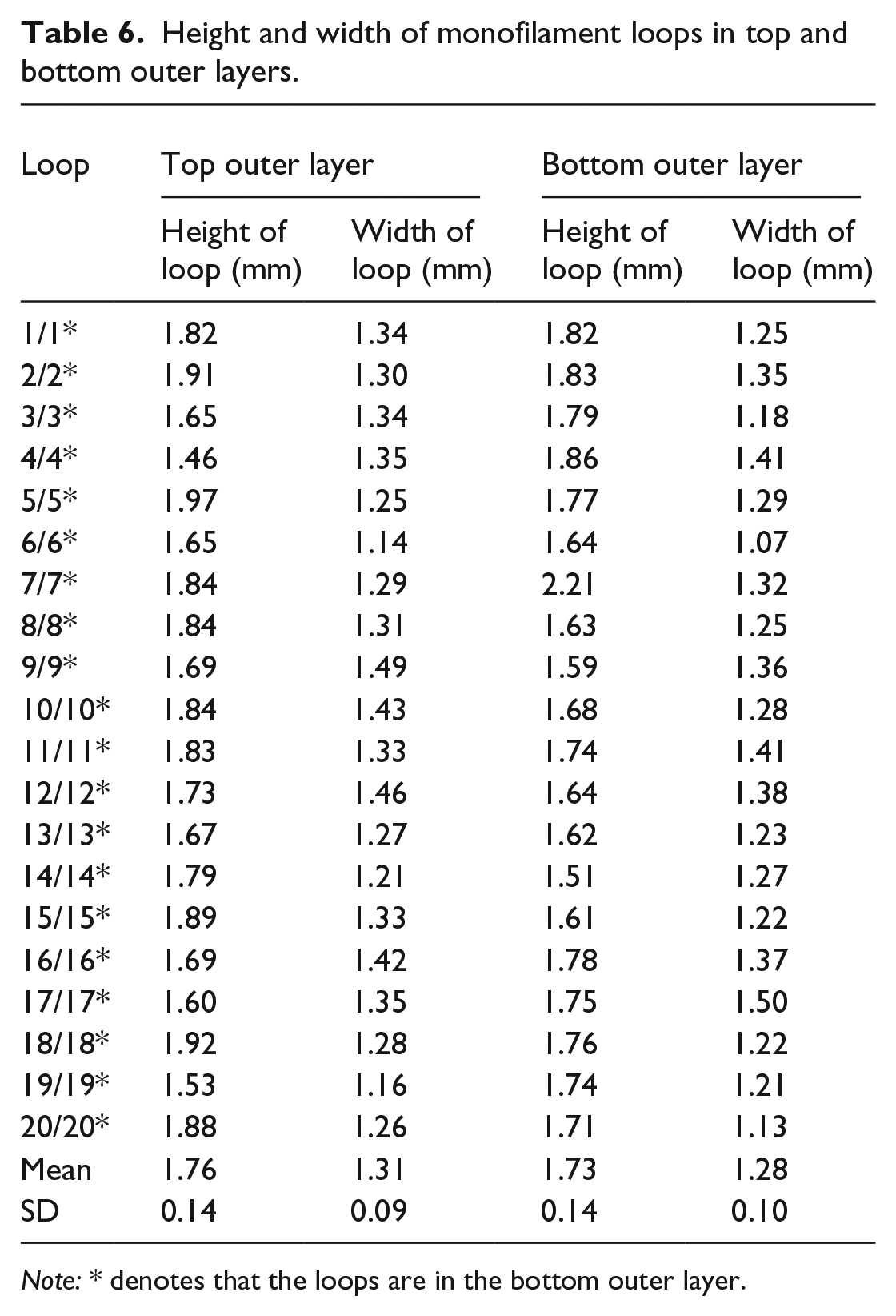
Note: * denotes that the loops are in the bottom outer layer.
Enclosed area of monofilament loops in top and bottom outer layers.

Note: * denotes that the loops are in the bottom outer layer
Conclusion
A quantitative structural analysis of a typical 3D mesh spacer fabric of thickness 10.3 mm for both the spacer layer and outer layers was conducted based on the precise geometry reconstructed from μCT scanning. The following conclusions can be drawn from the analysis:
3D mesh spacer fabric was a periodic but highly inhomogeneous structure whose spacer monofilaments were greatly different in length, curvature, and torsion, while monofilament loops in the outer layers were slightly different in loop height, width, and enclosed area.
The spacer monofilament lengths can be ranging from 9.43 to 10.77 mm. The difference in the length of the spacer monofilament in a unit cell can be up to 1.38 mm. A shorter spacer monofilament was more vertical and straight.
The curvatures of spacer monofilaments were highly fluctuant varying from around 0.1 to 0.3 mm−1 through the fabric thickness. There was no clear symmetry in curvature for the spacer monofilaments between two adjacent wales.
The torsions of spacer monofilaments can be positive and negative with different directions of twisting and had a certain degree of symmetry between two adjacent wales.
The findings suggest that yarn tension in warping and fabric stretching tension in heat setting should be carefully controlled to obtain high-quality 3D mesh fabrics, and geometric variations cannot be neglected in the simulation work on this type of fabric.
Footnotes
Declaration of conflicting interests
The author(s) declared no potential conflicts of interest with respect to the research, authorship, and/or publication of this article.
Funding
The author(s) disclosed receipt of the following financial support for the research, authorship, and/or publication of this article: The work described in this article was sponsored by the National Natural Science Foundation of China (11702062), Shanghai Pujiang Program (17PJ1400300), and Fundamental Research Funds for the Central Universities (16D110120).