
Abstract
The laminate model of thin-walled triaxial weave fabric composites (hereinafter referred to as shell-membrane structure) to calculate the equivalent tensile Young’s modulus and bending stiffness is derived. Three-dimensional beam element finite element model of shell-membrane structure under different loading angles is established, and the tensile and bending properties of shell-membrane structure were simulated, respectively. Both results of laminate model and three-dimensional beam element finite element model verify the “size effect,” indicating that the shell-membrane structure can be equivalent to linear material in the small deformation range. And the shell-membrane structure exhibits an in-plane quasi-isotropic property. These two methods are convenient for the mechanical properties solving in engineering applications.
Introduction
Braided carbon fiber has been widely used in large-scale lightweight structural parts such as aerospace structures. The modeling and analysis of its mechanical properties has become a research hotspot.1–5 Shell-membrane structure is named from its feature in engineer application. 6 The equivalent density of the perforated woven structure is lower than that of the densely woven structure. Woven composites have the potential to increase interlaminar fracture toughness and impact damage tolerance due to characteristic of intertwining. The shell-membrane structure is harder, easier to handle, and maintains structural integrity. Therefore, the shell-membrane is attractive for many industrial applications. The United States, Canada, and Europe all plan to apply shell-membrane structure to their satellite reflectors6–8
Modeling analysis of the shell-membrane structure started in the late 20th century. Fujita et al. 9 studied the tensile properties modeling method of this composite in 1993. In 2003, Hoa et al. 10 proposed the equivalent energy method for the mechanical properties of materials with porous composites and compared with the experimental results. Subsequently, the finite element model (FEM) of shell-membrane structure was proposed by Zhao et al. 11 of the Composite Research Center of Concordia University in Canada who conducted theoretical research and simulation analysis and developed two super element FEMs based on the theory of laminated plates and finite element method. The experimental data of multiple sets of test pieces were used to verify the theoretical solution. Since 2006, Kueh et al.12–14 from the University of Malaysia further studied the modeling method of the equivalent mechanical properties of the shell-membrane structure and did simulation to research the size effect. Comparative analysis was performed using a variety of modeling methods. Kueh used two-dimensional (2D) and three-dimensional (3D) beam elements in ABAQUS and solid elements to compare and analyze the model separately. The mechanical properties of the shell-membrane structure were analyzed. About the same period, Aoki and Yoshida 15 from the University of Tokyo studied the size effect of the shell-membrane structure, modeling, and experimental analysis of the structural loading in the 0° and the 90° direction (definition of 0° and 90° loading direction is shown in Figure 9). It is concluded that the shell-membrane structure exhibits quasi-isotropy when the size of the shell-membrane structure tends to be infinite. This conclusion is similarly studied and discussed by Kueh and Datashvili. da Rocha-Schmidt et al. 16 from the University of Munich did a lot of research on the space application of the shell-membrane structure. The mechanical modeling and simulation method is based on the modeling and analysis of FEM software. Rao et al. 17 from Donghua University analyzed the in-plane and out-of-plane mechanical properties of the shell-membrane structure by using the woven material homogenization modeling method based on micromechanics of composite.
Shell-membrane structure has certain symmetry, but it is not central symmetry structure at any angle. In the public published literature, the theory research and simulation analysis of the mechanical properties of the material in the irregular direction loading angle of shell-membrane structure are not mentioned in detail. To verify the degree of isotropy of the shell-membrane structure, the 3D beam element FEM under different loading angles is established and the laminated plate model for theoretical calculation is derived. The mechanical properties of different loading angles were analyzed. The variation of tensile Young’s modulus and bending stiffness along the loading angle and size deformation are obtained. Combined with the symmetry of the structure, the conclusion that the deformation form is similar at any loading angle can be obtained. For comparison verification, laminate model was derived. Its result shows isotropy on the theoretical solution either. Since both two methods’ results reveal “quasi-isotropy” in large size condition, the conclusion shell-membrane structure’s tensile and bending properties are “quasi-isotropy” in large size can be obtained.
Shell-membrane structure
Figure 1 shows a typical shell-membrane structure. The shell-membrane structure is constructed by interlacing carbon fiber bundles in three directions into each other. The carbon fiber bundles in three directions are angled 60° to each other, and the distance between each carbon fiber bundle is the same. This structure is made of a typical woven tape composed of 1000-filament T300 carbon fibers and a resin component Hexcel 913.
14
The composite has a dry area mass of

Shell-membrane structure.
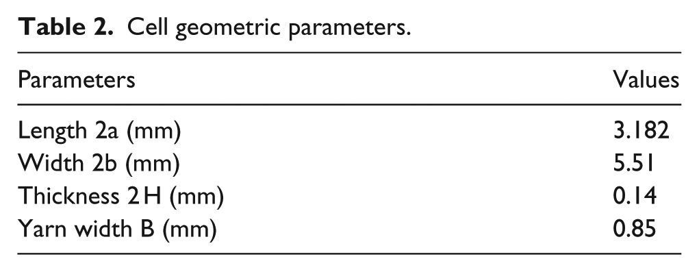
A schematic diagram of the shell-membrane structure is shown in Figure 2. The mechanical properties of the composite are obtained from material parameters of the carbon fiber and the epoxy, as shown in Table 1. Different sizes and dense woven mesh structures can be designed and manufactured by the triaxial weaving technique. A typical size of shell-membrane structure is shown in Table 2.

Schematic diagram of shell-membrane structure and unit size: (a) schematic diagram of a piece and a single cell of shell-membrane structure and (b) single cell’s size.
Elastic properties of carbon fiber T300/epoxy (at 25°C).

Cell geometric parameters.
Laminate model and calculation
Using the laminate theory, the shell-membrane structure is simplified into a laminate structure composed of three layers, and each layer’s thickness is same. Three layers are laminated as the angle of 60°/0°/60°. The simplified process is shown in Figure 3, and the schematic diagram of the simplified laminate model is shown in Figure 4.
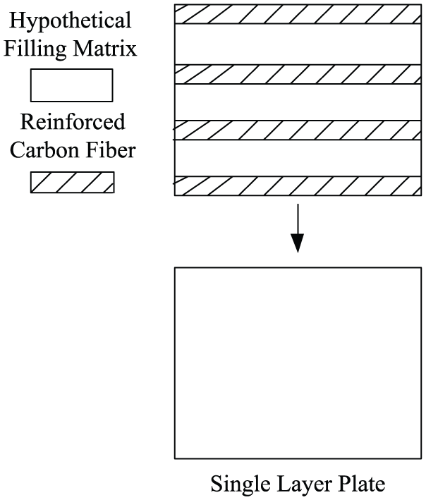
Single-layer plate simplified process schematic diagram.

Schematic diagram of equivalent three-layer laminate model.
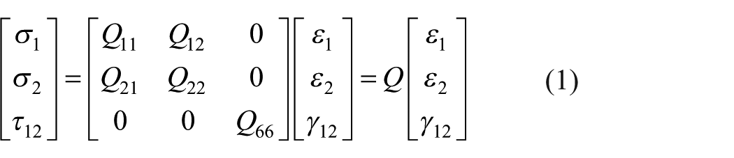
The single-layer stress–strain relationship is shown in equation (1)
The engineering elastic constants in equation (1) are

The 0 element in Q in equation (1) is because the single-layer plate is at plane stress state during tensile load.
According to the stress rotation axis formula, the relationship between the stress in β direction and the principal stress can be obtained in equation (6).
Table 2 shows the size ratio of a single carbon fiber bundle to the spacing. To calculate the Young’s modulus of a single-layer plate, assuming that the spacing between the carbon fibers is filled with a matrix, its equivalent elastic properties are

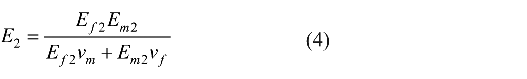

where

Combining (1), (2), and (6) can calculate the stress–strain relationship matrix Q of a single-layer plate rotated to angle β and the matrix of the three-layer laminate by summing the matrix Q of each single-layer plate.
The equivalent tensile Young’s modulus of the laminate can be obtained by inversely solving formula (2).
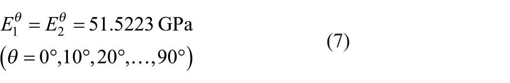
The loading angle θ is solved at 10 angles from

Analysis shows a result: the Q matrix is made up with a constant value.
Through theoretical derivation, the equivalent stress–strain matrix
Where t is the equivalent thickness


The first two diagonal elements have the same value in equation (9). So the equivalent stress–strain relationship matrix shows an isotropic relationship.
Further, the expression of the equivalent tensile Young’s modulus
Because of the calculated stress–strain relationship matrix
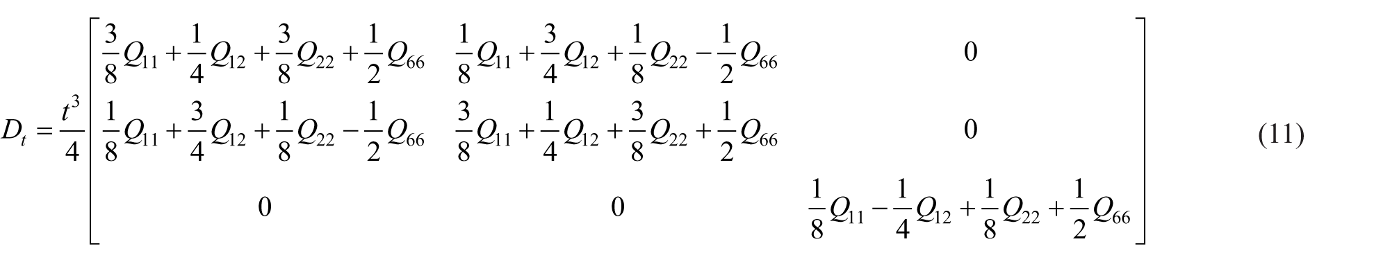
The theoretically derived bending stiffness matrix

FEM model
ABAQUS is used to establish FEM model. The 3D beam element is used because the load is not limited to in-plane load (B31 in ABAQUS/Standard 2018). The element size is set as 0.16 mm, because the shortest beams are only about 0.8 mm, to guarantee the accuracy of each part of the shell-membrane structure. According to the conclusions of Kueh 14 and Aoki and Yoshida 15 on the size effect, the test pieces of different sizes were used. According to the idea of using the 2D beam element in Kueh 14 to ignore the “wave effect,” the overlap of the braid is simplified. The joined zones are merged, so there is no change in thickness compared with the non-overlapping part. So the structure is like a plane mesh structure. The simplification can improve the efficiency of modeling.
Part of the FEM is shown in Figures 5 to 8. For verifying the “size effect,” the test pieces’ size is about

FEM model of 0° loading test piece.

FEM model of 10° loading test piece.

FEM model of 20° loading test piece.

FEM model of 30° loading test piece.
The loading angle coordinate system is showed in Figure 9. If one of the fibers is placed along the x-axis in the loading angle coordinate system, it is defined as 0° loading direction. And rotating 90° counterclockwise, it is called 90° loading direction (y-axis in loading angle coordinate system). Namely, the minimum angle between the axial direction of a carbon fiber and the positive direction of the x-axis is defined as the angle of the loading angle.

Tensile load diagram: (a) diagram of tensile load at 0-degree loading condition and (b) diagram of tensile load at 90-degree loading condition.
For the symmetry of the structure, when
Figures 9 and 10 show diagrams of tensile and bending loading condition for shell-membrane structure, respectively. In Figure 9, at the left side of the structure, there is simply support boundary condition. And at the right side of the structure, there is the tensile load Dl

Bending load diagram: (a) diagram of bending load at 0-degree loading condition, (b) diagram of bending load at 90-degree loading condition, and (c) slide view of bending load diagram.
The tensile Young’s modulus in FEM model is calculated using the definitions described in Materials Mechanics, which is shown in the equation (13)

In the equation,
Bending deformation is often measured by a matrix of bending stiffness. Since shell-membrane structure is a perforated woven structure, the formula of the pure bending displacement using the beam or the thin plate is not rigorous. So only the variation law of the given bending moment M and the generated rotation angle α is studied, and the ratio k under different loading conditions can reflect the variation law of the bending rigidity. The measured value against the bending stiffness is shown in equation (14)

Simulation and analysis
Tensile properties
Simulation was performed using ABAQUS/Standard. To derive the relationship between the equivalent Young’s modulus and the size, the

Tensile Young’s modulus simulation and fitting results.
The simulation results verify the “size effect” researched by Kueh 14 and Aoki and Yoshida 15 and Datashvili et al. 6 The results are given below: The variation of the size effect of the shell-membrane structure is linear. The larger the size, the smaller the change of the equivalent tensile Young’s modulus. The change when the length and width of the shell-membrane structure reach 100 mm or more. The relative error between the equivalent Young’s modulus and their average value under four loading angle conditions is within 5%.
Comparing the laminate model and FEM results, the relative difference is 0.9%. This indicates the effectiveness of the laminate model (Data shown in Table 3 and Table 4).
Considering the error cause by boundary conditions and computational accuracy in simulation, the behavior of tensile mechanical properties is approximately isotropic when the shell-membrane structure is in a large size.
Equivalent tensile Young’s modulus of shell-membrane structure at equivalent infinite size.

To verify the above conclusions, the large-scale FEM model of
Large size test piece simulation results.

As it can be seen from Table 4, equivalent tensile Young’s modulus’ error at different loading angles and the average value is less than 3.2%.
As shown in Figure 11, the equivalent Young’s modulus under 0° loading has a small range with size. And as the loading angle increases, the equivalent tensile Young’s modulus increases sharply with the size of the test piece. This phenomenon was named as “size effect.”
The reason why “size effect” occurs can be qualitatively explained from the perspective of energy method: as shown in equation (15): when the same structure is subjected to displacement load, its deformation at the free end will be larger than fixed edge. And the reaction force obtained at the fixed support will be smaller than the free end. Therefore, the reaction force
However, with the width increase, the reaction force
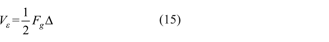
where
In Figure 11, the slope of the 0° tensile loading line is very small, but slope of 10°, 20°, and 30° tensile loading line is quite large. This is because the influence of “size effect” is less severe in 0° tensile loading. Namely,

Displacement cloud diagram

Displacement cloud diagram
Displacement cloud diagram

Displacement cloud diagram
Bending properties
To study the bending properties, on the one hand, it is necessary to analyze the relationship between bending moment M and rotation angle α. On the other hand, it is necessary to carry out simulation of moment response under different loading angle θ.
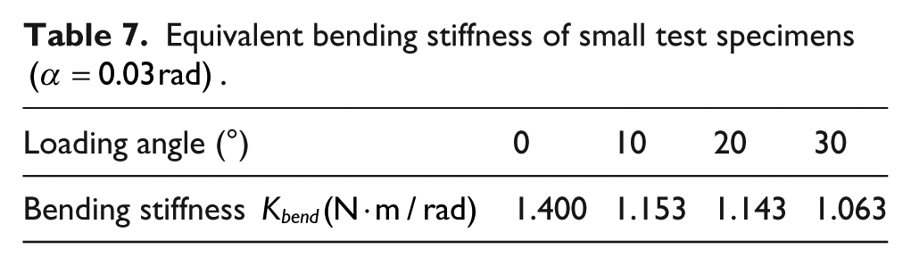
The simulation result is shown in Figure 16. Through the small-scale FEM model simulation, the fitting curve is shown in Figure 17 and the simulation data in Tables 5 to 7 were obtained. The equivalent bending stiffness obtained by the large-scale FEM is shown in Table 8.

Contrast of shell-membrane structure before and under pure bending load.

Moment-rotation angle simulation and fitting results.
Equivalent bending stiffness of small test specimens

Equivalent bending stiffness of small test specimens

Equivalent bending stiffness of small test specimens
Equivalent bending stiffness of large size test pieces

Figure 17 and Tables 5 to 7 show that the FEM model of the small size piece was used to perform under different loading angles. And difference of moment response exhibited under the same rotation angle is small. The simulation results show that the moment changed with rotation angle linearly. So the shell-membrane structure can be seen as a linear elastic structure under bending load. Tables 5 to 7 show the difference of moment at different θ are small, and the difference is within 5%. It can be considered that the bending deformation is approximately isotropic in any large scale.
Compared with the simulation results of tensile load, there is no “size effect” under bending load.
Conclusion
In this article, based on the equivalent method of the mechanical properties of the shell-membrane structure, the equivalent laminate model of the planar shell-membrane structure is derived by using the laminate theory of composite mechanics, and the FEM of the 3D beam element is established. These two models both verify the in-plane “quasi-isotropy” of shell-membrane structure and give the results of tensile and bending mechanical properties. Calculations and simulations yield the following conclusions:
Description of equivalent tensile modulus and bending stiffness matrix by the laminate model are derived. The calculation results show the tensile isotropic properties, and the bending stiffness matrix also reflects the isotropic property of bending deformation.
Three-dimensional beam FEM shows linear properties of shell-membrane structure in the small deformation range, and the tensile and bending deformations shows quasi-isotropy in large size condition.
The simulation results of the FEM model verify the size effect, and the simulation results of the quasi-isotropic properties of the tensile and bending mechanical behaviors under large dimensions are obtained. The result’s error between the 3D FE model and the laminate model is within 5%. And the simulation result is consistent with the result of the laminate model.
Compared with the large-scale model composed of large size beam element model, the simulation method of small size 3D beam element FEM combined with size effect and the equivalent calculation method of the laminate model simplify the model and decrease the complexity of calculating the mechanical behavior of shell-membrane structure, and increase the computational efficiency.
Footnotes
Acknowledgements
The authors would like to gratefully acknowledge the research team members of Xi’an Institute of Space Radio Technology for their advice and useful discussions in this research.
Declaration of conflicting interests
The author(s) declared no potential conflicts of interest with respect to the research, authorship, and/or publication of this article.
Funding
The author(s) disclosed receipt of the following financial support for the research, authorship, and/or publication of this article: This investigation was supported by funding National Natural Science Foundation of China under Grant No. U1537213.