
Abstract
At present, most space inflatable structures are composed of flexible inflatable fabrics with complex undevelopable surfaces. It is difficult to establish a multi-dimensional folding model for this type of structure. To solve this key technical problem, the motion folding method is proposed in this study. First, a finite element model with an original three-dimensional surface was flattened with a fluid structure interaction algorithm. Second, the flattened surface was folded based on the prescribed motion of the node groups, and the final folding model was obtained. The fold modeling process of this methodology was consistent with the actual folding processes. Because the mapping relationship between the original finite element model and the final folding model was unchanged, the initial stress was used to modify the model errors during folding process of motion folding method. The folding model of an inflatable aerodynamic decelerator, which could not be established using existing folding methods, was established by using motion folding method. The folding model of the inflatable aerodynamic decelerator showed that the motion folding method could achieve multi-dimensional folding and a high spatial compression rate. The stability and regularity of the inflatable aerodynamic decelerator numerical inflation process and the consistency of the inflated and design shapes indicated the reliability, applicability, and feasibility of the motion folding method. The study results could provide a reference for modeling complex inflatable fabrics and promote the numerical study of inflatable fabrics.
Keywords
Introduction
As the pace of deep space exploration accelerates, space inflatable structures have received increasing attention from various countries because of their advantages, such as low launch costs, light weights, high efficiencies, and small storage spaces. At present, most space inflatable structures are composed of flexible inflatable fabrics with complex surfaces, such as inflatable space habitats, 1 inflatable aerodynamic decelerators,2,3 inflatable antennae, 4 and inflatable solar arrays. 5 To overcome the volume limitations of existing launch vehicles, these structures are tightly folded and packed in a launch vehicle before launch. After entering orbit, they are expanded using an inflatable gas and rigidized to form stable space structures. Due to many issues during the inflation process, such as large deformations and the displacement of the fabrics, the nonlinearity of the material properties, nonlinear contact between the flexible fabrics, and very large curvature changes at the folds,6,7 the inflation and deploying process of the folded fabrics is the most important and dangerous process. Hence, determining whether space inflatable structures can be inflated from a tightly folded state to full state is one of the key issues related to the success or failure of a space launch mission.
Due to the high cost and long cycles of space experiments, the unsuccessful deployment of an inflatable structure will lead to a significant waste of labor and financial resources. In addition, ground tests of space inflatable structures are inevitably subject to external interference, such as air resistance, gravity, and instrument error, which are inconsistent with a space environment. However, with the rapid development of theory and computer hardware, numerical simulations have gradually become an important means for studying engineering problems due to their short calculation times, low resource consumption, and high accuracies. Establishing an accurate finite element folding model is the primary problem that must be solved to study the inflation process of space inflatable structures.
The direct folding method (DFM) is used to model inflatable fabrics that contain only two-dimensional planes, such as automobile airbags, 8 space inflatable tubes, 9 and parachute canopies. 10 Salama et al. 11 used this method to establish a Z-folded folding model of a cylindrical tube. The numerical results of the inflation process were consistent with the experimental data. Gao et al. 12 used the DFM to establish a good folding model for a parachute canopy, and the inflation process of the parachute was stable and controlled. However, the DFM cannot be used to establish a folding model of space inflatable structures with three-dimensional surfaces.
At present, the main folding methods for three-dimensional surfaces include the reverse modeling method (RMM) and the initial matrix method (IMM). The RMM, which is based on graphical deformation, first shifts some of the constraint nodes regularly while the rest of the adjacent nodes have a certain displacement due to the pulling of the constraint nodes, which achieves the fold modeling of an inflatable fabric. Liu et al. 13 first used the RMM to build a folding model for a cylindrical surface that had good mesh quality and regular folds. However, the RMM can only be applied to simple developable three-dimensional surfaces (such as cylinders). Moreover, because the RMM does not follow any conservation laws during the fold modeling process, the accuracy of the numerical results is not guaranteed.
The IMM first builds the folding model of a simple geometry (such as a cube or cuboid) and subsequently modifies the folding model with a mapping relationship between the real inflatable geometry (such as a cylinder) and the simple geometry. Tanavde et al. 14 proposed this method and applied it to fold modeling of passenger airbags. Zhang et al. 15 wrote an automatic fold modeling program using the IMM and successfully established a folding model for a cylindrical airbag. Because the number, type, and arrangement of the elements between the folded finite meshes and the reference finite meshes must be identical, the difficulty of using the IMM to build a folding model arises when establishing the mapping relations with a complex algorithm. The IMM is limited to the element types and calculation parameters of the algorithm, which will affect the quality of the elements. Consequently, the IMM has a low modeling accuracy and it cannot be applied to complex undevelopable surfaces.
Since the above surface folding methods must obtain a continuous plane for a curved surface, they cannot be applied to the undevelopable surfaces in mathematics. However, many new inflatable fabrics have complex shapes with undevelopable surfaces, and their folding patterns are difficult to model using existing methods. For example, the inflatable aerodynamic accelerator (IAD) is composed of six undevelopable torus surfaces, and the connections between the surfaces are also very complex. In addition, the compression ratio of the IAD in three dimensions is very large due to the volume limitations of the launch vehicles. Therefore, the existing numerical studies on inflatable fabrics with complex surfaces are constrained by the fold modeling technology. To solve this key problem, we proposed the motion folding method (MFM) in this study.
Principle of MFM
The core ideas of the MFM can be explained as follows: (a) the flattened finite element model of a three-dimensional complex surface is obtained based on an arbitrary Lagrangian–Eulerian algorithm (ALE), (b) the folded finite element model is established by applying the motion load of the nodal groups to the flattened finite element model, and (c) the initial stress method is used to modify the folding model errors of the MFM, which improves the accuracy of the numerical calculations.
Principle of surface flattening
Because an inflatable fabric is very sensitive to the magnitude, direction, and duration of the load, the interpenetration of the mesh faces, distorted elements, and stress concentration areas can occur easily, which creates problems. It is difficult to establish a flattened finite element model for inflatable fabrics with complex curved surfaces using the conventional uniform external load approach. In this study, a non-uniform flow field force was applied to the fabric, and the flattening process of the complex curved surface was transformed into the calculation of a fluid-structure interaction based on the ALE method.16,17
The fabric material and fluid region in the ALE method were described using Lagrange meshes. The meshes deformed with the material deforms, which ensured the conservation of mass. The numerical calculations for the surface flattening process in this study did not involve the transfer and conversion of internal energy, so only the momentum equation needed to be solved

where ρ represents the density,
According to the principle of virtual work, the above equation could be discretized in the spatial domain

where BIj is the geometry matrix represented in index notation; σji represents the stress; t-i represents the external forces; NI and NJ are shape functions;
Based on equation (2), the finite element method was used to calculate the node displacements. After calculating the node acceleration, the central difference scheme 17 was used to discretize the semi discrete equation

where vn + 0.5 is the velocity of the next half time step, vn–0.5 is velocity of the previous half time step, tn is the nth time step, and
The motion and deformation of the meshes in each time step were calculated using the above discrete equations of space and time. The Lagrangian grid followed the movement of the material grid. Since the fluid material could not withstand shear stress and tension, the grid of the fluid material became distorted. Therefore, after each Lagrangian time step, it was necessary to smooth the distorted fluid material grids based on the “equipotential” zoning method, 18 in which the topological relationship of the grids did not change and the flow field information was transported to the updated grids based on advection methods (Figure 1).

Operation at each time step: (a) the initial time, (b) solving the flow field based on Lagrangian arithmetic, and (c) smoothing and transporting information.
To guarantee the grid quality, the distorted fluid material grids had to be smoothed by the equipotential method, which was developed by Winslow. Because the flow field was fixed in this study, only the fluid elements were restructured. The node coordinates in the physical domain were obtained by solving the Laplace differential equation

Because a fluid element moved from its position at the end of the Lagrange calculation to its new position after mesh smoothing, there were momentum, mass, and energy fluxes through the six faces of the element. The convection terms were updated based on the finite volume method, and its three-dimensional form was as follows

where ϕ represents the flux, V is the element volume, the subscript j denotes the adjacent element, the subscript A denotes a calculation element, and
Principle of fold modeling
The folding model of a flattened surface can be established with the motion load method, which introduces the movement of the fabric into the process of fold modeling. It can reproduce the physical folding process more realistically, and the irregular folds obtained with this method are more realistic. According to the ALE algorithm above, the flattened surface of a three-dimensional complex surface with a finite thickness can be obtained. The prescribed motion, as well as the deformed and fixed regions of the folded finite element model, is defined based on the actual folding process. The finite element method is used to apply the motion load to the prescribed motion region, and the deformed region produces disordered folds. After the numerical calculation, the final folding model is obtained.
Figure 2 shows a schematic representation of the rotation folding process of a flattened surface with a finite thickness. We defined the local system by specifying a vector ul in the direction of the local x-axis xl, which was the rotation axis EF, and a local in-plane vector vl. After normalizing ul, the local xl, yl, and zl axes were given as follows


Schematic representation describing the fold modeling process.
A transformation matrix

The translational and rotational acceleration vectors of the nodes in the fixed region were all zero. According to the actual physical folding process, the translational acceleration vector

The flattened surface was modeled as a membrane structure 20 during the folding process. The finite element formulation was derived from the principle of virtual work

where

where
Principle of model error modification
To obtain the final folding model with a large volume compression ratio, wide ranges of motion of the membrane elements had to be used during the folding process. Because the membrane elements were subjected to external forces in order to move, problems such as mesh stretching and stress concentration at the folds were inevitably generated during the folding process. Initial model errors occurred in the final folding model and caused a discordance of the shapes in the inflated state and the original design, which affected the accuracy and stability of the numerical calculations. Therefore, the model error modification technique based on the initial stress method 21 was introduced in order to eliminate the influence of the initial model errors.
The initial stress method used the finite element model with the actual designed shape as the reference mesh, which was the unfolded finite element model in this study. In addition, another finite model was used as the mapping mesh, which was based on the final folding model established by the MFM. Since the mesh topological relationship, including the number, type, and arrangement of the elements, did not change during the folding modeling process, the mapping relationship between the mapping and reference meshes could be naturally established.
As shown in Figure 3, the strain of the element could be obtained via the relationship between the reference and mapping meshes. The strain calculation equation was as follows
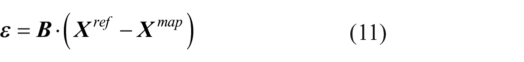
where

Initial stress modification method.
According to the material constitutive equation, the initial modification stress could be expressed as follows

where
The initial stress could be modified using the mapping mesh at any time in the explicit finite element calculation, which replaced the initial model. 17 Due to the model errors of the folding process, the mapping mesh in Figure 4(a) had some distorted elements and it could not reach the actual designed shape. After the distorted elements were modified by the initial stress, the mapping mesh in Figure 4(d) achieved the actual shape, which was consistent with the reference mesh.

Example of stress modification: (a) mapping mesh with some distorted elements, (b) reference mesh without distorted elements, (c) stress modification during numerical calculation, and (d) mapping mesh with the actual designed shape after stress modification.
Principle of inflation simulation
In this study, the numerical simulation of the inflation process of the folded fabric was carried out using the control volume method. 22 The gas in the airbag satisfied the following equation of state
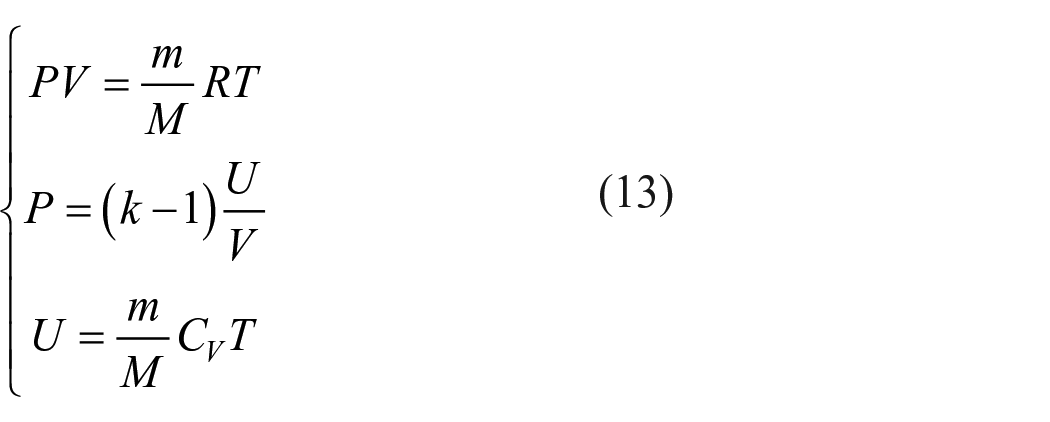
where P, V, T, m, and M represent the pressure, volume, temperature, mass, and molar mass of the gas, respectively, R is the molar gas constant, k is the ratio of the specific heat at constant pressure to the specific heat at constant volume, CV is the specific heat at constant pressure, and U is the internal energy of the gas.
The equation of motion of the folded fabric elements could be written as follows
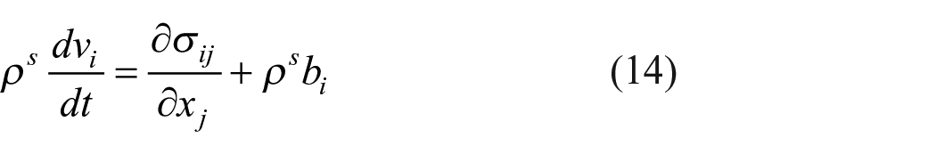
where ρs and vi represent the density and moving speed of the element, respectively; σ ij is the total internal stress tensor; bi represents the external volumetric force; xj represents the space coordinate; and t is time.
The spatial position of each element at a certain moment could be obtained from the moving speed of the structural elements. Thus, the volume of the airbag could be calculated using Green’s Theorem, as follows
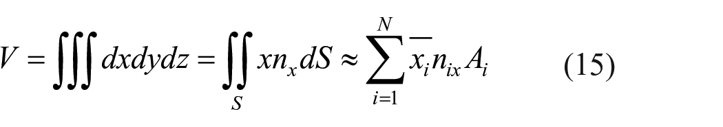
where for each element i, -xi represents the average x coordinate, nix represents the direction cosine between the x direction and the element’s normal vector, and Ai represents the surface area of the element.
Example
Due its small ballistic coefficient, low aerodynamic heating, light weight, and foldable packaging, the IAD has become a new type of deceleration technology for heavy-load Mars exploration. On 26 April 2018, the Beijing Institute of Space Mechanics and Electricity conducted the first reentry flight test at a 60 km altitude for an IAD in China. 23 This test validated the IAD’s working principle, working procedure, and several key technologies. Figure 5 shows the flight profile of the IAD reentry flight test. The successful inflation and deployment of the IAD was directly related to the safety of the exploration mission.
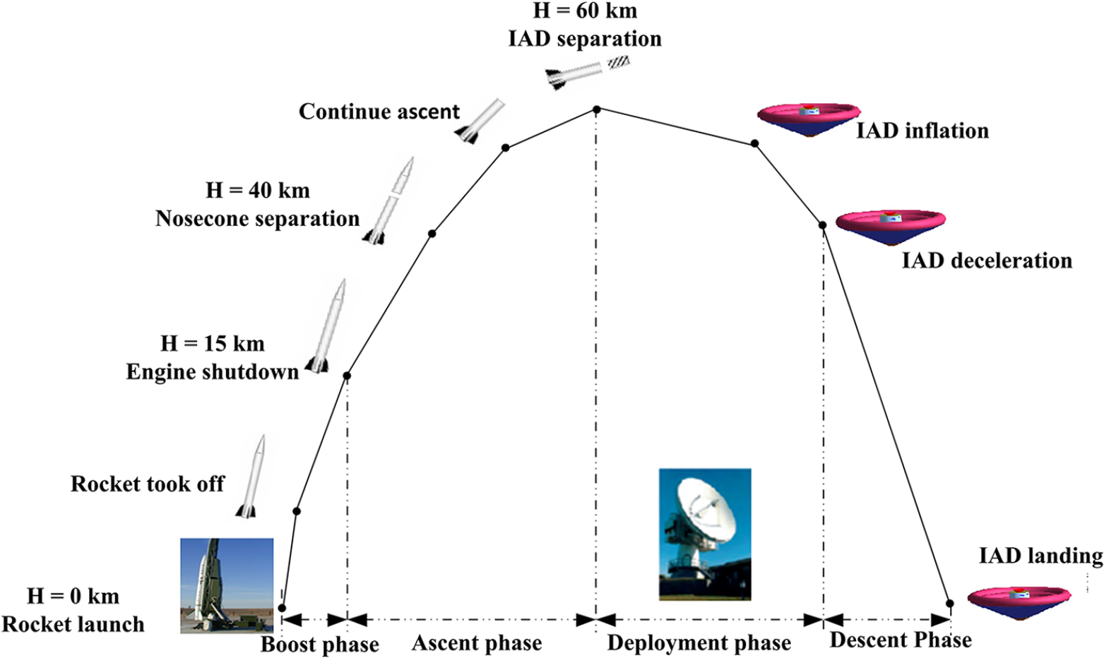
IAD trajectory overview.
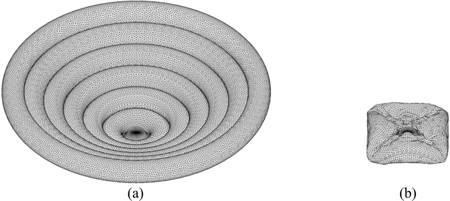
The IAD was composed of six complex undevelopable tori, a thermal protection system, structural straps, and a rigid center body, which used a center-closed rotational folding process (Figure 6). None of the existing folding methods could establish a three-dimensional compressed folding model for this IAD. However, the MFM proposed in this article could solve this critical problem. In this method, a full-state finite element model was first established based on the actual size of the IAD (Figure 7), which was composed of triangular meshes. Next, the folding model was established by the fluid-structure interaction and the motion load methods. To modify the initial model errors during the folding process, the initial stress method was used during the inflation process.

The shapes of the IAD in the flight test: (a) folding state at launch and (b) deployment state at landing.

The shapes of the IAD: (a) geometry and (b) original finite element model.
Surface flattening modeling
The axial compression modeling of the IAD was performed by the ALE algorithm. This algorithm is a nonlinear dynamic folding method. Since the ALE algorithm described in this article did not need to establish a body-fitted flow field mesh, the flow field mesh composed of tetrahedral elements interpenetrated with the structural mesh (Figure 8(a)). The upper part of the flow field adopted the velocity inlet condition, the flow field was surrounded by the free-slip wall condition, and the lower part of the flow field was the non-reflective boundary condition. The velocity inlet condition and the fabric material parameters are shown in Table 1. In addition, to obtain a compressed IAD, a rigid wall had to be created in the lower part of the IAD.

Axial compression of the IAD using the ALE algorithm.
Numerical calculation parameters.
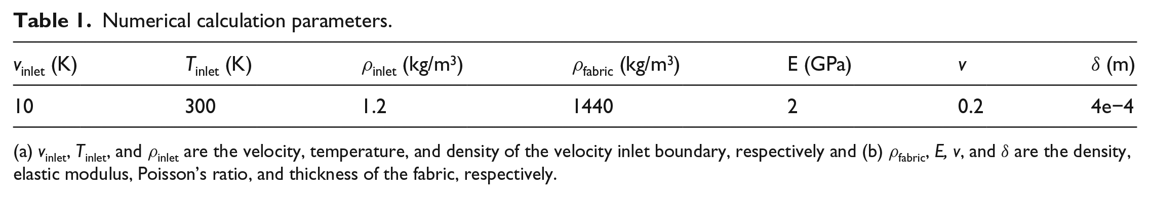
(a) vinlet, Tinlet, and ρinlet are the velocity, temperature, and density of the velocity inlet boundary, respectively and (b) ρfabric, E, v, and δ are the density, elastic modulus, Poisson’s ratio, and thickness of the fabric, respectively.
Figure 9 shows the process of surface flattening based on the ALE algorithm. The rigid wall and the center body were fixed constraints, and they were not coupled with the flow field. Therefore, the airflow could flow directly through the fixed structures. The IAD was gradually compressed and flattened by the non-uniform flow field force. Irregular folds and wrinkles were created during the calculation of the surface flattening process, which was consistent with the actual physical compression process. When the IAD was compressed to a certain height, the computation was stopped to avoid stress concentration. Finally, the flattening model of the IAD (Figure 6(b)) changed its axial height to 0.105 m, and its axial compression rate reached 91.7%.

Surface flattening process based on the ALE (velocity vectors and stress contours).
Fold modeling
The motion load method was used to simulate the radial compression of the IAD, which introduced the motion of the fabric into the fold modeling process. First, a local coordinate system was established in order to apply the motion load to the specific part of the flattening model, after which the folding model was obtained by finite element numerical calculations. Since the IAD fabric material was very thin, the problem of mesh faces intersecting each other occurred easily during the fold modeling process. In this study, a contact algorithm based on a penalty function 24 was used to simulate the contact between fabrics, and the intersection of the mesh faces with each other was prevented by increasing the contact stiffness and thickness of the fabric in the contact algorithm.
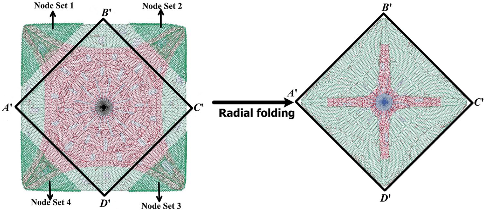
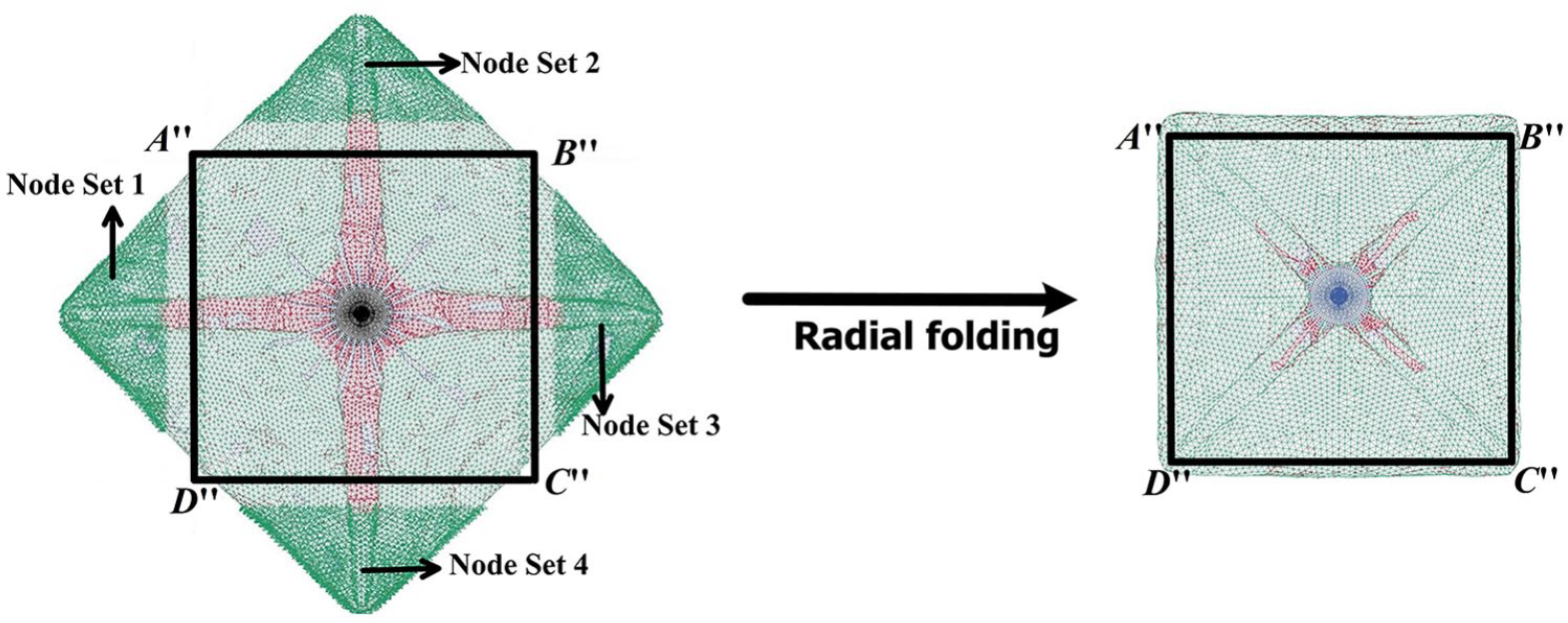
As shown in Figure 10, first, four sets of local coordinate systems were defined for the four node groups. A motion load rotated by 180° around the x-axis of the local coordinate system was subsequently applied to each node group. The folding process of each node group, as shown in Figure 11, was synchronic, and an orderly fold formed along the axis of rotation. Therefore, the radial dimension of the IAD was reduced by the rotation folding in four directions. To facilitate the next radial folding, the axial compression of the folding model using the flow field force based on the ALE algorithm was required after each radial folding. To meet the engineering constraints for the IAD assembly space, the IAD was subjected to another three radial folding processes (Figures 12 to 14) in order to obtain the final IAD folding model. Table 2 shows that the volume compression rate of the final folding model could reach 94%, and both the axial and radial dimensions could meet the limitations of the IAD assembly space of a rocket carrier.

First radial folding of the IAD.

Fold modeling process based on the motion load.
Second radial folding of the IAD.
Third radial folding of the IAD.

Fourth radial folding of the IAD.
Geometric parameters of the initial model and the folding model.
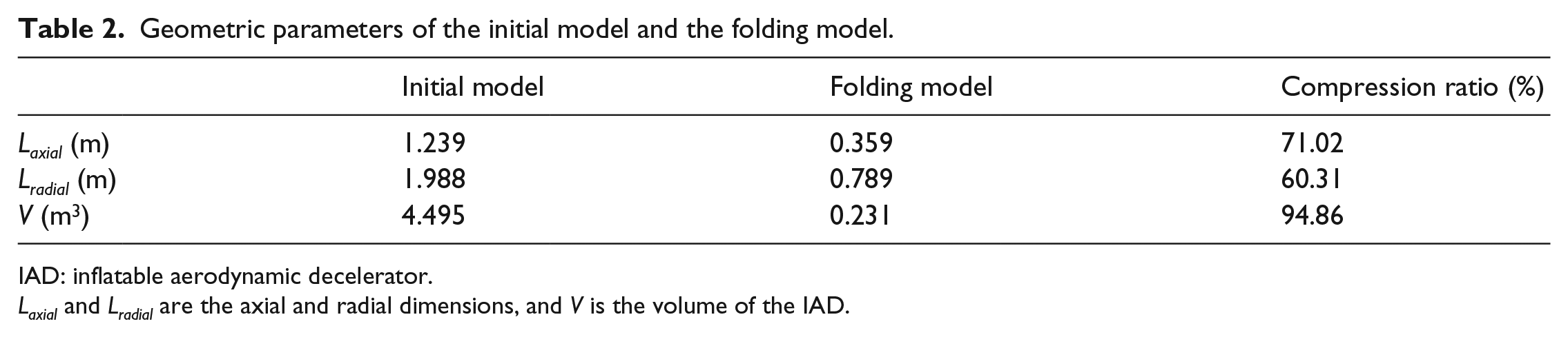
IAD: inflatable aerodynamic decelerator.
Laxial and Lradial are the axial and radial dimensions, and V is the volume of the IAD.
Finite element model
The numerical calculation of the inflation process of the IAD in a vacuum environment was carried out with the control volume method. The parameters for the inflation process are shown in Table 3. The mass flow rates of the different tori were different, which improved the consistency of the pressure in the different tori during the inflation process. The torus stopped inflating when the internal pressure of the airbag reached 60 kPa. The initial unfolded model was used as the reference mesh, as shown in Figure 15(a), which was used to obtain the initial modification stress. Model A modified the folding model errors with the initial stress method at the initial time of the numerical calculation (at t = 0 s), which ensured the stability and order of the IAD inflation process. To clearly distinguish the initial stress effect, the stress modification of model B was applied to the folding model during the inflation process (at t = 2 s).
Calculation parameters.

The finite element model of the IAD: (a) reference mesh of the actual designed shape and (b) mapping mesh of the final folded shape.
Analysis of inflation process
Figure 16 shows the numerical results of the IAD during the inflation process. Since there were no model errors during the inflation process, the inflation process of Model A was more stable and orderly than that of Model B. The IAD of Model A reached the actual designed shape in 1.3 s. Due to the presence of model errors, the partial folds of Model B failed to deploy to the actual designed shape at 1.99 s. After the stress modification of the model errors, the partial folds were successfully expanded, and the IAD reached the actual designed shape at 2.04 s. Therefore, the folding models of the IAD established by the MFM were successful, and the actual designed shape was achieved.
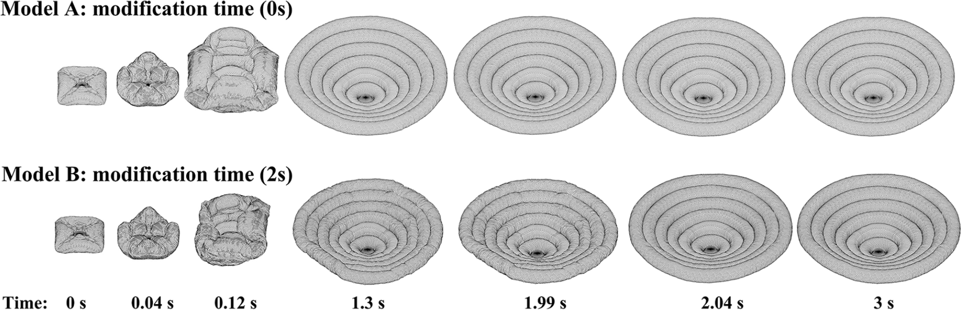
Geometric shapes of the IAD during the inflation process.
Figure 17 shows that the pressure changes with time in the different tori of Model A were almost the same, which increased the stability of the inflation process and verified the rationality of the mass flow rate parameter design. The design values of the volume and pressure were achieved in 0.25 s and 1.3 s, respectively. According to Figure 18, the wrinkles of tori 4–6 of Model B were suddenly opened near 0.3 s because of the large number of folded layers, the high-volume compression rate, and the initial model errors, causing a step change in the volume and pressure. When the design pressure was reached, Model B could not reach the design volume due to the initial model errors. After the initial model errors were modified by the initial stress, the volume of Model B finally reached the design value. In summary, the folding models of the IAD established using the MFM could successfully reach the design values of volume and pressure.
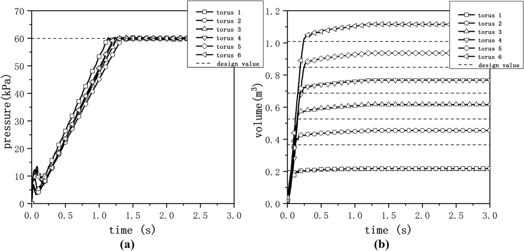
Pressure and volume in different tori of Model A over time: (a) internal pressure and (b) internal volume.
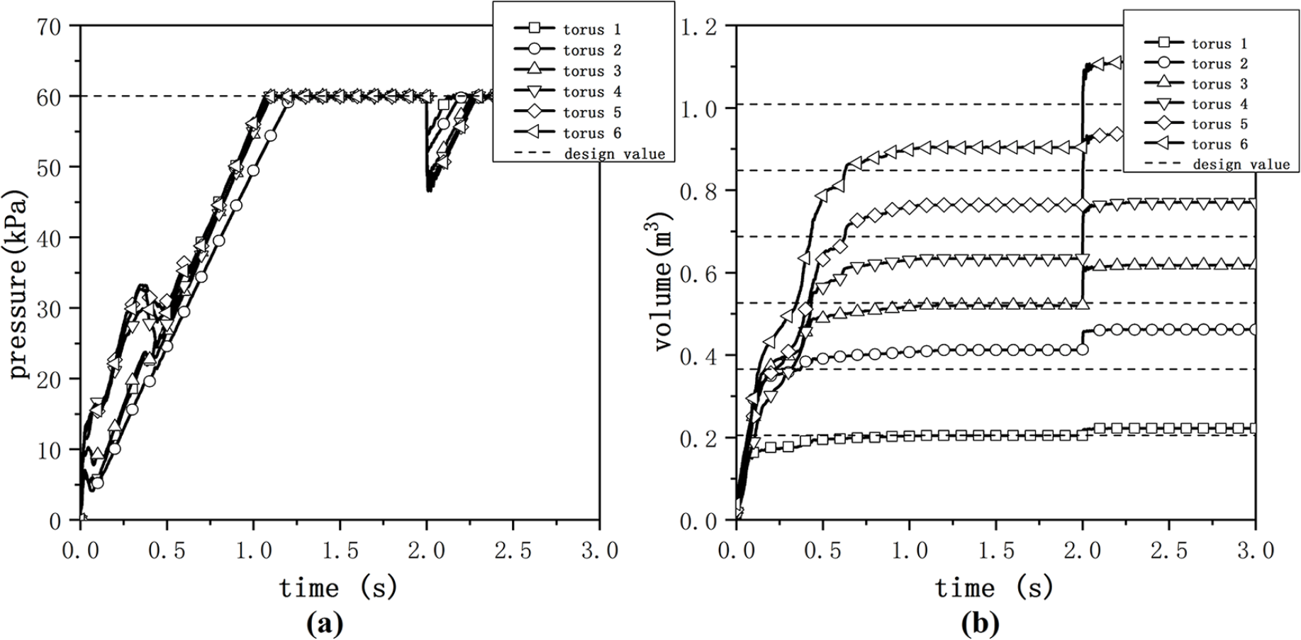
Pressure and volume in different tori of Model B over time: (a) internal pressure and (b) internal volume.
By comparing the numerical results of Model B before and after stress modification, we studied the effect of the initial stress. First, because the initial stress modified the folding model errors, the internal volume of each torus increased and reached the design values shown in Figure 18 at 2 s. Second, the distorted elements shown in Figure 19 were mostly distributed near the rotation axes in the fold modeling process, which resulted in unreasonable local stress concentration areas. However, most of distorted elements disappeared after stress modification, which made the overall stress contour of the IAD more uniform and reasonable. Finally, Figure 20 shows that after the stress modification, the equivalent stress and strain of elements A and B were reduced by more than 85% and 94%, respectively. The initial stress eliminated the geometric errors of the MFM, and the areas of the two elements reached their respective original values. In summary, the initial stress modified the folding model errors of the MFM, reduced the number of local stress concentration areas and distorted elements, and improved the accuracy and stability of the numerical calculation.

Effective stress contours of Model B: (a) before stress modification and (b) after stress modification.

Strains, stresses, and areas of the two elements over time: (a) effective strain, (b) effective stress and (c) element area.
Conclusion
The MFM, based on the ALE method and the motion load method, was proposed in this study. The MFM can be applied to any complex undevelopable surface. The MFM was used to establish a folding model of an inflatable aerodynamic decelerator with complex undevelopable surfaces, and numerical calculations for the inflation process were carried out. The MFM had the following characteristics:
The non-uniform axial flow force was applied to the original finite element model by the ALE algorithm, which greatly reduced the axial dimension of the three-dimensional complex undevelopable surface and produced a flattened finite element model that was easy to fold.
The motion load method was used to rotate the specific node group around the specific local coordinate system. This fold modeling algorithm not only easily produced a folding model with a large radial compression rate but also was consistent with the actual physical folding process.
The initial stress method modified the model errors during the folding process, reduced the problems of stress concentration and mesh distortions at the folds, and improved the stability and accuracy of the numerical calculations.
A multi-dimensional folding model of a complex undevelopable surface was established using the MFM. The folding model had a high-volume compression rate. The numerical results demonstrated that the folding model exhibited high numerical accuracy and stability.
Because the MFM performed the fold modeling using finite element numerical calculations, it exhibited strong universality and it could be used for inflatable fabrics with arbitrary shapes. The final folded shape was a three-dimensional compressed shape formed by axial compression and rotational folding, which could be applied to the fold modeling of space inflatable structures in the field of aerospace. Finding ways to apply the MFM to other engineering fields and increase the diversity of the folded shapes is the subject of future work.
Footnotes
Declaration of conflicting interests
The author(s) declared no potential conflicts of interest with respect to the research, authorship, and/or publication of this article.
Funding
The author(s) disclosed receipt of the following financial support for the research, authorship, and/or publication of this article: This work is supported by the National Natural Science Foundation of China (grant no. 11972192) and A Project Funded by the Priority Academic Program Development of Jiangsu Higher Education Institutions (PAPD).