
Abstract
Reciprocating yarn-guiding system is a device for evenly and efficiently winding processed yarns into corresponding packages according to process requirements. Based on the traditional reciprocating yarn-guiding system and the linear magnetic driving mode, the linear magnetic reciprocating yarn-guiding system is proposed in this article. First, the technological requirements of conical package are analyzed, and the polynomial motion law based on reciprocating yarn-guiding mechanism is discussed emphatically. Second, the motion characteristics and operation mechanism of driving parts of reciprocating yarn-guiding mechanism are studied. The maximum acceleration models are established on two kinds of magnetic field analysis theories. Then, the appropriate models have been chosen by comparing the simulation results. And then, the movement functions of reciprocating yarn-guiding mechanism are ensured through the maximum acceleration model and the motion laws. Finally, the yarn distributions winding different types of yarns are simulated. The simulation results showed that the linear magnetic reciprocating yarn-guiding system based on polynomial motion law not only satisfied the fundamental requirements of package but also cut down one-stroke time and improved the efficiency of winding.
Keywords
Introduction
The package plays an important role in yarn storage, dyeing, and machining; it has always been the focus attention on the textile industry to prepare high-quality winding and improve the digitalization and automation of the reciprocating yarn-guiding system.1–4 At present, there are some reciprocating yarn-guiding systems such as forming cam and link pole reciprocating yarn-guiding system, rotary motor and ball screw reciprocating yarn-guiding system, and crank-link and sliding block reciprocating yarn-guiding system. Italy’s RATTI firm 5 proposed the “R362-S” double twisting machine. In the reciprocating yarn-guiding system, the differential micro gear set drives the forming cam to rotate, which makes the slider in the chute move reciprocally. The slider is articulated with the triangular component and matches the connecting rod to complete the reciprocating motion of the guide rod. The yarn-guiding range can be changed by altering the relative position of the crank and cooperating with the gear set and worm gear.
Researchers like Zhang et al. 6 put forward that “rotary motor and ball screw” reciprocating yarn-guiding system was applied to new type twisting machine. Its principle is shown in Figure 1. Servo motor drives the ball screw to realize reciprocating motion of the transmission pole. The transmission pole is rigidly connected with the yarn-guiding pole, thereby enabling the yarn-guiding hook on the yarn-guiding pole to guide the yarn movement. The stroke and frequency of yarn-guiding are adjusted by changing the forward and reverse time and rotary speed of the servo motor. In order to protect the safety of equipment and personnel, proximity switch and limit switch are set at the key position of yarn-guiding stroke. This project, extensively applying electromechanical integration technology, had many advantages such as simple structure, easy maintenance, and low rate of malfunction.

“Rotary motor and ball screw” reciprocating yarn-guiding system.
Wang et al. 7 came up with the reciprocating yarn-guiding system based on servo control and crank-link mechanism. Figure 2 presents a diagram of mechanical principle of reciprocating yarn-guiding system. The servo motor drives the crank on the disk to rotate, cooperating with the link pole to drive the slider to complete reciprocating motion in the chute. The crank length is altered by turning the speed of the motor and the position of point Q at the disk in the figure; thus, stroke and frequency of yarn-guiding are changed. This system, applying crank-link mechanism to reciprocating motion, worked out problems like overoperation and overcurrent because of frequent pro and con rotation.

Crank-link and sliding block reciprocating yarn-guiding system.
The above three kinds of traditional reciprocating yarn-guiding systems have improved the production efficiency of package. However, the forming cam and link pole reciprocating yarn-guiding system has a complex structure, which is not conducive to the assembly, debugging, and maintenance of the mechanism. In addition, when changing the yarn-guiding stroke, the mechanism needs to stop and change the crank length and gear transmission ratio, which is time-consuming and laborious to operate, and affects the efficiency of the system. Although the “rotary motor and ball screw” reciprocating yarn-guiding system simplifies the complexity of the drive mechanism and improves the automation of the system, it also has the problems of overcurrent caused by frequent positive and negative rotation of the motor and overshoot of the yarn-guiding pole. The crank-link and sliding block reciprocating yarn-guiding system solves the problem of overcurrent of motor and overshoot of yarn-guiding pole, but the transmission mechanism is still troublesome in changing the yarn-guiding stroke, which affects the winding efficiency. Because of the motion characteristics of crank-connecting pole mechanism, the mechanism puts forward higher requirements for the material of link pole. In summary, a new reciprocating yarn-guiding system is proposed to improve winding efficiency and overcome the problems of the reciprocating yarn-guiding mechanisms.
At present, electromechanical equipment is developing to higher speed, automation and flexibility, and other direction because of higher demands in global market.8–13 On the other hand, modern manufacturing industry claims that electromechanical device should give consideration to demands such as simplification of mechanical structure, improving lifetime and trying to energy conservation and emission reduction during producing.14–17 In recent years, proven manufacturing technique of linear induction motor produced by ND-Fe-B (neodymium iron boron) and rapid development of modern control technology makes linear magnetic driving wildly use to liner field like feed system of CNC (computer numerical control) machine tool, maglev transportation system, and textile machinery.18–23 Direct-drive technology with linear magnetic mechanism as the core has been the main direction for technology upgrade of reciprocating yarn-guiding mechanism.24–26
The linear magnetic reciprocating yarn-guiding system is proposed from areas for improvement of reciprocating yarn-guiding systems mentioned above, combining with linear drive and real-time detection technology. The polynomial motion law of reciprocating yarn-guiding mechanism is established through the analysis of conical package process. And then, the structure and operation mechanism of its driving parts are briefly introduced. The acceleration models of reciprocating yarn-guiding mechanism are established using two kinds of magnetic field analysis theories. Finally, the distributions of yarn in conical winding process with two different yarns are studied.
Linear magnetic reciprocating yarn-guiding system
The linear magnetic reciprocating yarn-guiding system consists of a package-forming mechanism and a reciprocating yarn-guiding mechanism. Its principle is shown in Figure 3.

Operating principle of linear magnetic yarn-guiding reciprocating system.
The yarn, rounded yarn-guiding hook, is winded to package through friction drum actuated by servo motor in the package-forming mechanism. The rotary speed and cylinder number information of package are measured by the speed sensor and transmitted to control end to adjust the rotation of package to meet the technology demands. The reciprocating yarn-guiding mechanism is composed of driving parts, linear guide, and so on, accomplishing the reciprocating yarn-guiding movement of yarn-guiding pole. Encoder transmits in real time the speed and displacement information of the driving platform to the control end to improve the control precision of reciprocating yarn-guiding motion. Stop blocks are added to protect the safety of personnel and equipment at both ends of the linear guide.
Analysis of conical package technology
Because conical package is widely used in storage and transportation of twisted yarn, and its process requirements have certain representativeness, the process requirements of conical package are taken as the research content of the motion law of linear magnetic reciprocating yarn-guiding system. The schematic diagram of the conical package is shown in Figure 4.

Conical package diagram.
Based on the basic winding theory,27,28 the relationship between the winding point M’s velocity VM along the package bus and reciprocating yarn-guiding point H’s speed VH is present in equation (1)

where L is the length of the free end of the yarn (mm) and
From equation (1), the smaller the length of the free end of the yarn, the shorter the time between the yarn’s helix angle and the predetermined helix angle, and the smaller the difference between VM and VH.
In the process of winding conical package, the relation between the linear velocity VO at the winding point M and the distance from the package axis to the small end is shown in equation (2)

where R1 is the radius of small end of package (mm), x is the distance from the winding point M along the winding axis to the small end (mm),
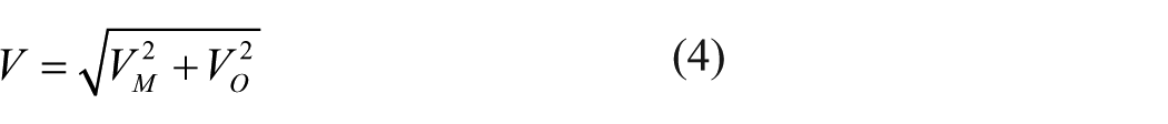
The relations about the speed of winding are shown in equations (3) and (4)

The rotary speed of package should be reduced according to certain law in order to ensure equal density winding of conical package. Limited to the paper length, and the rotary speed of package in a certain period of time does not change much, it can be assumed that it remains constant. This article will focus on discussing the reciprocating yarn-guiding mechanism’s motion law about equal density winding of conical package.
Motion law of reciprocating yarn-guiding mechanism
Reciprocating yarn-guiding mechanism is the key composition directly affecting the quality of fiber and package and having part of impact on yarn processing in subsequent processes. Therefore, the reciprocating yarn-guiding mechanism should meet the following requirements in the operation process 29 :
The running situation of reciprocating yarn-guiding should be stable. When winding the conical package, smooth acceleration changes can reduce the shock impact on the mechanism, which is conducive to the stable operation. The movement law of reciprocating yarn-guiding mechanism should pay attention to the problem of transient acceleration function during commutation and the selection of acceleration and deceleration time. Choosing a reasonable motion control function of the reciprocating yarn-guiding mechanism can effectively improve the package quality.
It has anti-overlapping function. In the process of winding, yarn overlapped will seriously affect the unwinding quality. The reciprocating yarn-guiding mechanism should adopt appropriate anti-overlapping method to avoid the occurrence of yarn-ring overlap.
According to the above requirements and the cylindrical package motion law of ball screw, the preliminary drafted motion law of conical package of reciprocating yarn-guiding mechanism in this system (small end to large end) is shown in Figure 5.
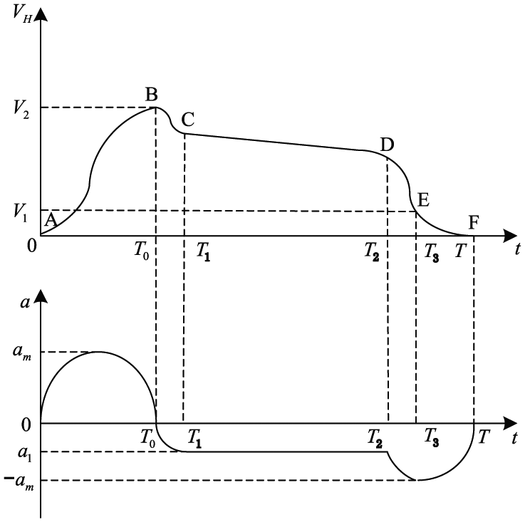
Motion law of reciprocating yarn-guiding mechanism due to conical package.
According to the curve form of Figure 5, the acceleration curve in the [0, T0] can be represented by a parabolic function, as shown in formula (5)

Its boundary conditions are as follows

Then, its function in this interval is as follows

The acceleration curve in the [T0, T1] is shown in formula (7)

The acceleration curves in the [T1, T2], [T2, T3], and [T3, T] can be gained similarly. So the acceleration curve in the [0, T] is shown in formula (8)
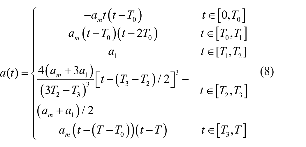
where am is the maximum acceleration of reciprocating yarn-guiding mechanism (m/s2) and a1 is the acceleration of reciprocating yarn-guiding mechanism moving small end to big end of package (m/s2). And, the value of a1 is

Therefore, its speed and distance curves are presented in equation (9)

Their boundary conditions are shown as follows

To sum up, the motion law of the conical package of the reciprocating yarn-guiding mechanism can be preliminarily determined. In the actual winding process, the motion law also needs to take into account the overlapping of yarn, hard edge, and convex edge of package.
Improving motion law of reciprocating yarn-guiding mechanism
Anti-overlapping processing
As the package diameter increases gradually, the rotated rotary speed of package needs to be reduced in order to maintain the same ascending angle winding. When the rotary speed of package reaches a certain range, the winding rotary times of the package decrease in unit time, which will result in the overlap of the yarn ring. The research shows that it can make the winding package yarn dense and even to choose appropriate winding ratio in the initial stage of winding. 30 In addition, it can also avoid yarn overlap to change slightly yarn-guiding stroke, increasing the distance between adjacent winding cycles. 31
Anti-hard edge processing
In the process of winding, the distance between yarn-guiding hook and the winding point should be small possibly to reduce the influence of yarn free length on winding density and package forming. The closer the distance is, the flatter the edge of the package will be. The reciprocating yarn-guiding mechanism passes through the acceleration and deceleration area at the reversing position in a relatively short time so that the yarn loops at both ends with high winding density are as few as possible. However, excessively short acceleration time will not only cause high acceleration during commutation process and make the system vibrate, but also leave the driving parts in an overload state, which is not conducive to the stable operation of the system for a long time. In a word, due to the winding process parameters of different varieties of yarn, the motion control function and the values of deceleration time need flexible selection according to the technical requirements.
Mechanical analysis and calculation of reciprocating yarn-guiding mechanism
As the reciprocating yarn-guiding mechanism is rigidly connected with the yarn-guiding pole, the motion of the yarn-guiding pole is the same as the reciprocating yarn-guiding mechanism. Because there is no intermediate transmission link in the linear magnetic drive mode, although this drive mode improves the transmission efficiency, the load change and the end effect of the primary magnetic field will have a direct impact on the accuracy of the mechanism. In order to meet the requirements of high-quality package, on the one hand, higher control accuracy needs to be satisfied. On the other hand, the transmission mechanism of reciprocating yarn-guiding mechanism and the main factors affecting its motion performance are analyzed to determine the specific values of the main parameters in the motion law of yarn-guiding or to provide reference for the yarn-guiding travel planning. Figure 6 presents the forced situation of reciprocating yarn-guiding mechanism.

Forced situation of reciprocating yarn-guiding mechanism.
The forced condition of reciprocating yarn-guiding mechanism in Figure 6 can be obtained as follows

where F is the electromagnetic thrust of driving parts (N); f is the system friction (N);
The system friction f satisfies the following relation

where u is the friction factor between linear guide and slider.

where

Formula (13) describes the relevant parameters of the acceleration of the reciprocating yarn-guiding mechanism. In order to further study its motion characteristics and determine the range of parameters of yarn-guiding motion law, it is necessary to analyze and solve the relevant parameters in the formula.
Operating principle of driving parts
Figure 7 shows the structure diagram of driving parts of reciprocating yarn-guiding mechanism. Assuming that the magnetic effect of the permanent magnet in the outer space only affects the space of winding coil, the magnetic effect of the driving parts can be equivalent to the magnetic effect of the reciprocating yarn-guiding mechanism. According to Figure 7, because of its structure with symmetry and repeatability, the change trend, that is, magnetic induction intensity of a single permanent magnet in space, is analyzed using the two magnetic field analysis theories: molecular current theory and equivalent magnetic charge theory, and the mathematical models of magnetic induction intensity about reciprocating yarn-guiding mechanism are established.

Model structure of driving parts.
Magnetic field model based on molecule current theory
The magnetic effect of rectangular permanent magnet is the superposition of magnetic effect manifested by inner ring molecule current based on Ampere’s assumption of molecular electric current. Its result is same as the magnetic characters overlaid by surface current of four sides. The magnetic strength of single permanent magnet can be equivalent to superposition of magnetic field formed by surface current of four sides.32,33 Magnetic field distribution model of single magnet based on the molecule current theory in space is shown in Figure 8.

Magnetic field distribution model of single magnet based on molecule current theory.
Suppose that the point P in space outside of magnet is (x0, y0, z0) and point Q on four sides of magnet is (x, y, z). P0 is the projection of point P on the plane which is passing on point Q and parallel to Plane XOY. P1 is the intersection point of Plane AB with line passing point P0 and being parallel to Y axis.
Magnetic induction intensity

Regard the Plane AB as calculating object, magnetic induction intensity

In actual condition, the magnetic induction intensities along axis x and axis y are ignored because they have little influence on electromagnetic thrust. Therefore,

Similarly, magnetic induction intensity is produced by three another sides’ current along axis z at point P can be received. Consequently, magnetic induction intensity

The following assumption is made

Therefore, the operation result of formula (18) can be shown by formula (20)

The magnetic field distribution along the axis z of permanent magnet in space is related not only to the properties of magnet but also to the position of reference point according to formula (20). It is obviously proved that
From equation (21), the magnetic field along the axis z in the space is symmetrical about the magnet geometric center line

Magnetic field model due to equivalent magnetic charge theory
According to the theory of equivalent magnetic charge, the magnetic effect of rectangular magnet is produced by arranging imaginary magnetic charge in regular order along the direction of magnetization.35,36 Therefore, the magnetic field intensity generated by magnet in space can be equivalent to the vector sum of the magnetic field intensity generated by all magnetic charges in the volume of magnetized body. And magnetic monopoles have not been found yet, so it is assumed that magnetic charges always appear in pairs called magnetic dipoles. On the other hand, only the surface magnetic charge exists but no magnetic charge exists in the magnet.
37
So we can make an assumption that magnetic charges

Magnetic field distribution model of single magnet due to equivalent magnetic charge theory.
The magnetic potential

where r is the distance between the field point and source point, s is the boundary surface where magnetic charges exist in the magnet,

where

The magnetic field strength

Where


In this article, the magnetic field distribution along the direction of magnetization is only discussed, so the magnetic field distribution along the direction of axis Z is only studied and the magnetic field strength


The magnetic induction intensity
The following formula can be obtained from equation (31)

Formula (31) shows that the magnitude of the magnetic induction along the magnetization direction of a single permanent magnet is symmetrically distributed with respect to the neutral plane along the magnetization direction when the permanent magnet is determined.
Maximum acceleration model of reciprocating yarn-guiding mechanism
When the magnetic poles of multiple permanent magnets are distributed alternately, the magnetic induction intensity of the space magnetic field along the direction of magnetizations

where p and n are, respectively, the number of magnets distributed along the x and y axes (piece). Therefore, the normal suction can be obtained from equation (32), as shown in equation (33)

where s is the acting area of normal suction (m2).
Similarly, the electromagnetic thrust mathematical model of reciprocating yarn-guiding mechanism is established by combining the electromagnetic force calculation formula and formula (32). Ignoring the end effect and cogging effect of the driving mechanism, the electromagnetic thrust of the reciprocating yarn-guiding mechanism is shown in equation (34) according to the calculation formula of electromagnetic force
where m is number of magnets contained in longitudinal length; L is effective length of the winding in the magnetic field region.
According to equation (13) and equations (33) and (34), reciprocating driving mechanism’s maximum acceleration

where
Simulation of system motion
The magnetic induction intensity of rectangular permanent magnet in space is studied by two kinds of magnetic field analysis theories, and two kinds of magnetic induction intensity distribution models are established in equation (32). Two kinds of magnetic field models are simulated. The simulation results are analyzed and compared. The suitable formula for calculating the maximum acceleration of reciprocating yarn-guiding mechanism is selected.
Maximum accelerating calculation of reciprocating yarn-guiding mechanism
In this article, the secondary of reciprocating yarn-guiding mechanism is rectangular permanent magnet based on ND-Fe-B material. The main parameters of single permanent magnet are shown in Table 1.
Main parameters of driving parts.

PM: permanent magnet.
Combining the parameters in Table 1 with equations (20) and (31), when the reference plane is 1 mm away from the upper surface of the magnet, in other words, when z0 = 5 and z = 5, the images of

Magnetic field distributions based on molecule current and magnetic charge: (a) z0 = 5 and (b) z = 5.
In the case of the permanent magnetic properties, Figure 10(a) and (b) compares the magnetic field distributions at 1 mm from the upper surface of the magnet using different magnetic theories. We can find that there is an apparent change of magnetic field between the outer magnet space and the inner magnet space along the magnetization direction, which is a significant reason to the thrust fluctuation and the influence on control accuracy, worthy to be discussed. On the other hand, the variation of magnetic induction intensity in inner magnet space is decreasing. The error introduced between can be ignored to some extent. Therefore, we can make an assumption that the magnetic induction intensity at the center axis of the magnet along the direction of magnetization is taken as the average magnetic induction intensity of the magnet at that distance, that is

Their images are shown in Figure 11.
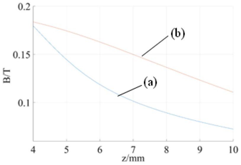
Variation of magnetic field intensity along the axis of magnetic center.
Figure 11(a) and (b) shows that the magnetic induction intensity tends to decrease with the increase in the distance from the upper (lower) surface of permanent magnet. The weakening trend first increases and then decreases in Figure 11(a). From Figure 11(b), the weakening trend first decreases and then increases. The trend shown in Figure 11(a) is more in line with the actual situation compared with the measured magnetic induction intensity of permanent magnets; that is, the magnetic field model based on molecular current theory can better describe the spatial magnetic induction intensity distribution of permanent magnets.
When n = 2 and p = 2 and n = 6 and p = 1, the variation trend of magnetic induction intensity
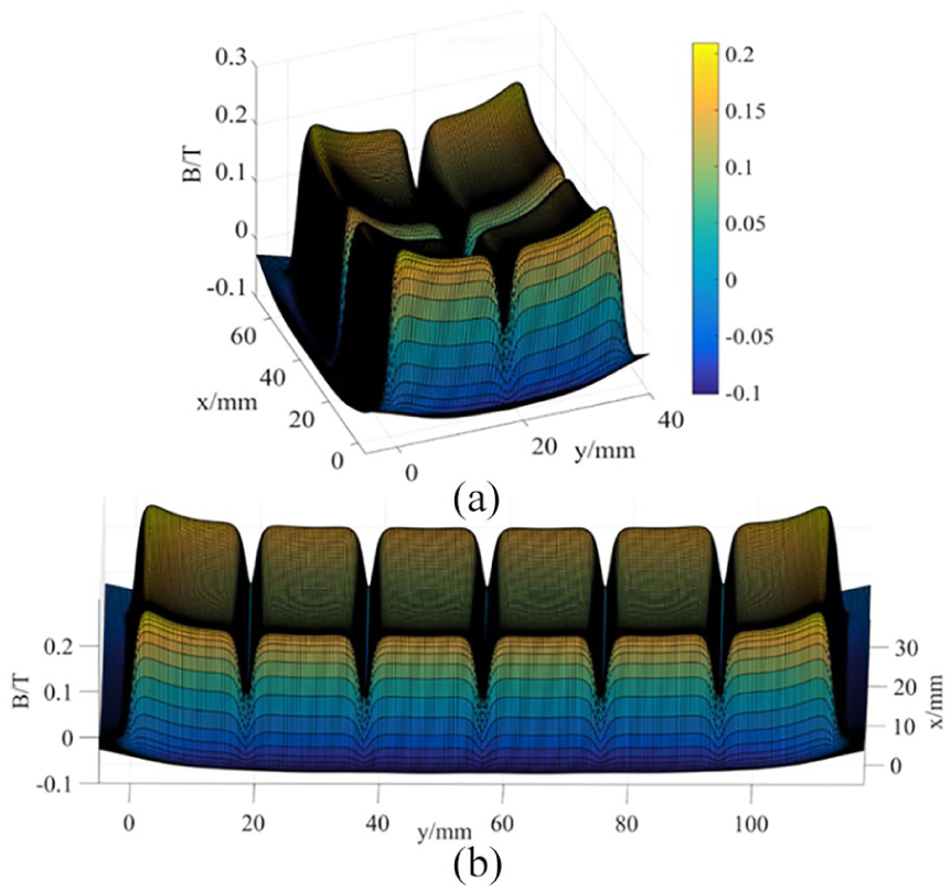
Magnetic induction intensity distribution of multi-block magnets: (a) n = 2 and p = 2 and (b) n = 6 and p = 1.
Figure 12(a) and (b) shows that due to the coupling of magnetic field, the magnetic induction intensity between adjacent magnetic fields is relatively stable, and the magnetic field at the outer boundary of the magnets on both sides is obviously greater than that at the middle. Because of the gap between the adjacent permanent magnets in the manufacturing and installation process, it will make the magnetic field change suddenly and the motion control of the reciprocating yarn-guiding mechanism more difficult. Therefore, the reciprocating yarn-guiding mechanism should be avoided as far as possible to run to the limit position while setting the reciprocating yarn-guiding stroke. Besides, it is more suitable to run at high speed so that the influence of magnetic field mutations on reciprocating yarn-guiding mechanism can be avoided.
When the air gap height of driving parts is 1 mm and n = 9 and p = 1, the maximum acceleration of reciprocating guide mechanism is shown in formula (36)

In the running process of reciprocating yarn-guiding mechanism, excessive acceleration may lead to system vibration and instability. On the premise of satisfying the package process and the manual requirements of driving parts, the reciprocating guide motion law am can be set as 4.5 m/s2 in order to ensure the safety of equipment and personnel.
Package yarn distribution
In section “Maximum accelerating calculation of reciprocating yarn-guiding mechanism,” the maximum acceleration of reciprocating yarn-guiding mechanism has been determined. The specific values of other parameters in Figure 5 also need to be calculated and solved in combination with the process requirements of winding and the process parameters of yarn varieties. Table 2 shows the production process parameters of several representative cotton thread types. 38
Manufacturing technological parameters of several typical cotton types.

According to the data in the above table and equations (8) and (9), the motion function of reciprocating yarn-guiding mechanism winding different yarn varieties such as C9.7 × 2 and 97.2GCV45 can be determined, as shown in Figure 13(a) and (b). The red, blue, and green curves in the figure are the acceleration, velocity, and displacement curves of the reciprocating yarn-guiding mechanism, respectively.

Motion law of reciprocating yarn-guiding mechanism: yarn type is (a) C9.7 × 2 and (b) 97.2GCV45.
From Figure 13(a) and (b), it can be concluded that the frequency of reciprocating yarn-guiding mechanism in this system is 83 times per minute and 98 times per minute when winding two kinds of yarns, which have improved the yarn-guiding’s frequency and the efficiency in unit time for same type of yarn and package compared with traditional reciprocating yarn-guiding mechanisms. In addition, the structure of reciprocating yarn-guiding mechanism need not be changed in the process of different motion functions’ simulation. And the corresponding driving function is input directly to achieve specific yarn-guiding process requirements. This driving mode can greatly shorten the downtime and effectively improve the efficiency of the mechanism in the actual operation process. The proportion of acceleration and deceleration time at the reversing point is significantly reduced because of the high acceleration for the mechanism.
And the winding rotary speed remains constant for a certain period of time, the yarn distribution can be simulated by equations (2) and (4). When the cone top half angle

Distribution of package yarn: yarn type is (a) C9.7 × 2 and (b) 97.2GCV45.
The results of Figure 14(a) and (b) show that, except for the high density of yarn winding at the commutation point, the density of the rolled yarn is relatively uniform. The conical motion law based on polynomial form can realize the equal density of yarn winding well. On the other hand, higher winding speed will result in a denser distribution of the yarn, which will increase the volume of the winding while making the loops more easily overlapping.
Conclusion
This article proposes a linear magnetic reciprocating yarn-guiding system to improve the winding efficiency and control accuracy of existing system. A polynomial yarn-guiding motion law based on this system is proposed. The following results can be obtained by simulation.
The motion law based on polynomial type has been established to suit the higher winding speed for this system. The described theories about magnetic field analysis to study the running performance of reciprocating yarn-guiding mechanism are more mathematically rigorous. And the accuracy of molecular current theory in magnetic field analysis has been verified. The rationality and correctness of motion law based on the winding process have been confirmed through the simulated result.
However, much of work needs to be done before the motion law is utilized to actual application. Further research on linear magnetic reciprocating yarn-guiding system should be carried out.
Footnotes
Declaration of conflicting interests
The author(s) declared no potential conflicts of interest with respect to the research, authorship, and/or publication of this article.
Funding
The author(s) disclosed receipt of the following financial support for the research, authorship, and/or publication of this article: This project is supported by National Natural Science Foundation of China (Grant No. 51775389).