
Abstract
To tap the full potential of reinforcing fibres for lightweight construction of sustainable carbon fibre–reinforced plastic components, woven three-dimensional reinforcement structures open up innovative approaches by integrating functional features. In this work, a novel three-dimensional shuttle weaving technology was taken advantage of to study carbon reinforcement structures with uninterrupted load trajectories from three points of view. Mechanical principals, economic and environmental issues were focused to provide an overall picture. Near-net-shape reinforcement fabrics with load trajectory–compliant yarn paths and interconnected layers that are interwoven in thickness direction were objects of investigation. The effects of a closed fabric selvedge, only producible by shuttle weaving, were investigated too. The here presented novel technology enables complex woven reinforcement structures that otherwise would demand several fabric layers leading to limited properties and lower performance of the carbon fibre–reinforced plastics due to missing interconnections between the layers. The studies on exemplary rods revealed a close relationship between different three-dimensional weave structures and the carbon fibre–reinforced plastic’s mechanical properties. The three-dimensional structures were woven in a single-step process and subsequently infiltrated with epoxy resin in the Vacuum Assisted Process (VAP®) and mechanically tested. Rounding off, universal guidelines for the layout of three-dimensional fabrics for rods were derived therefrom. The economic and environmental aspects of the complete process line were compared to the conventional manufacturing procedures for carbon fibre–reinforced plastic by material flow cost accounting. Looking at sustainability, material flow cost accounting showed that lightweight three-dimensional components with integrated features can be produced cost-effectively with less environmental impact by the novel weaving technology. Its capability for high-quality serial production of three-dimensional reinforcement structures is evident, which was one major result of the work.
Keywords
Introduction
A considerable potential for lightweight construction can be raised, especially at transitions and joints, using adapted reinforcement structures with optimized load trajectories. Frequently used load- or form-fitting metal connecting elements (hinges, screws, rivets, bolts, nodes) are heavy and induce considerable weakening in the load trajectories because the load-conducting reinforcement fibres at the joints are interrupted due to the design. In addition, strength and stiffness of bonded joints between pure fibre-reinforced composites must exclusively be ascertained by adhesive–matrix adhesion.
Today, a complex construction geometry consisting of node connections and area components is commonly achieved by a laminate structure of individual layers prior to consolidation. 1 Thus, the layers are not interconnected, but only laminated. Beyond that, not-to-be-neglected waste material is already generated by the cutting process of every single fabric layer. These standard processes are very labour-intensive and do not guarantee the utilization of the semi-finished product’s total fibre strength. Rational series production is significantly limited due to these aspects. 2 In addition, the simulation-optimized load paths get misaligned during the pre-forming processes of complex three-dimensional (3D) reinforcement structures, thus derogating the reliability of safety relevant components.
Existing solutions for node elements based on penetrated thin pipe shells3,4 and replacement of multi-layered woven fabrics which produce a profile with a spatial contour by folding and arranging individual layers5–7 are reported. Also, large-area multi-layer fabrics with layers interwoven by interlock binding threads 1 as well as hollow and spacer fabrics with flat and multi-curved cover layers8–11 are described in the state of the art.
Derived from this, the working hypothesis of this study is that complex 3D-woven textile blanks for carbon fibre–reinforced plastics (CFRPs) are technically superior, more economical and environmental friendly than known standard textile blanks in the appropriate field of utilization.
Hence, the objective was to examine 3D fabrics made by new weaving techniques compared to standard solutions for CFRP reinforcements from three perspectives: technical, economic and environmental. Special knowledge for the creation of high-performance and sustainable CFRP components should be generated and transferred into guidelines.
As a mechanical approach, the load trajectories’ characteristics of the reinforcing fibres had to be transferred from the bundled force application point to the surrounding component areas. Its implementation with a new weaving methodology based on Jacquard-controlled shuttle weaving technology was aimed at. The force-conducting reinforcing fibres in textiles can be placed close to the final contour in width, height and depth by this technology. Production of textile blanks for completely new, very complex fibre composite components with significantly improved strength and stiffness shall be enabled. Expected technical process advantages are as follows:
Continuous fibres on closed reinforcement fabric selvedges;
Crossing weave structures between fabric layers and interlock threads;
Flexibly designable width and thickness profiles of fabrics;
Geometry-adapted fibre paths in near-net-shape fabrics.
Weaving technology with 3D weaving machine
The 3D-woven fabrics are multi-layered fabrics that differ from 2D fabrics by having warp or weft threads interlaced through the thickness binding the layers together. Desired weave structures can be realized relatively easy with 3D weaving process. A single-weft insertion system (shuttle or other) is sufficient to create multiple fabric layers. The fibre density of the layers is limited only by the number of warp yarns available.
Boussu et al. 12 proposed clear definitions of 3D warp interlock fabrics with instructive representations of such sample fabrics. The publication discusses the advantages of 3D weaving such as gentle yarn processing, simple implementation of geometric specifications, for example, near-net-shaped 3D fabrics and the possibility of producing multi-layer woven fabrics instead of joining layers of fabrics together. In addition to these, 3D weaving process ensures less effort for cutting single layers, assembly and simple insertion of structures into mould and reduced labour and material cost. However, there are a few drawbacks for 3D weaving such as damage due to abrasion and high manufacturing cost. Lower fibre volume fraction is mentioned as a technological disadvantage.
A detailed overview on 3D-woven fabric architecture with focus on trusses and hollow fabrics is given by Chen et al. 13 The 3D-woven fabrics are subdivided depending on the constructions. Two main groups are angle-interlock and orthogonal-interlock fabrics in which several layers of threads were held together by separate interconnecting threads.14,15 They are suitable for achieving structures with maximum stiffness. In addition, we redefined the ‘stitched’ 13 type through the thickness architecture as ‘interweave’ which has the same categories as in ‘interlock’ (Figure 1). However, ‘interweave’ are weaves of fabric layers that are interconnected using separate binding threads (central stitching 13 ), or fabric layers are directly interconnected with existing yarns by local binding points of adjacent fabric layers (self-stitching 13 ). Both weft and warp threads can be used for it. These interweave constructions have very good structural integrity and are crash-resistant.

Weave structures of 3D multi-layer fabrics.
The design software ‘3D Weave Composite’ from EAT GmbH was used and further developed throughout the research project in cooperation with the software provider, to create adapted 3D reinforcement structures.
3D weaving machine
The novel modified 3D weaving technology allows full electronic control of each warp yarn by an UNIVAL®-Jacquard machine (Stäubli, Horgen, Switzerland). Multiple sheddings of different size can be formed simultaneously. In combination with a MAGEBA SL XT 1100/1 shuttle weft insertion system, moved by rapiers for weft inserting, variable weft length can be introduced along the width of the fabric. Shuttles work in four insertion levels (Figure 2), allowing any number of fabric layers to be created on top of each other. This unique arrangement of flexible shed formation and weft insertion guarantees a smooth processing when brittle fibres are used. However, the solid advantage is the endless loop of carbon weft yarns that creates closed-loop trajectories along the fabric structure for high-quality serial production with entire near-net-shape geometry.

Novel modified 3D weaving machine MAGEBA SL XT 1100/1.
Objects of investigation
As investigation objects should not be too complex for identification of principal effects, we chose a control rod and a pipe connector which could be used in one T-joint assembly (Figure 3). The control rod consists of loops at the ends connected by a flat section. It is used to connect components and thereby transmit forces. The purpose of the pipe connector is to connect the central rod to the pipe as a movable assembly (Figure 4). The woven part of both the components looks the same (Figure 5). The difference is that in case of the pipe connector, the loops at the end are rotated 90° about the woven plane (Figure 6). For the near-net-shaped 3D fabrics to be developed, fundamental generic elements were the base. Six individual variants of textile blanks comprising differences in additional reinforcement rovings as stuffer yarns will be discussed below.

Possible application of the investigation objects as T-joint assembly, for example, as a hexapod element.

Flexible T-joint demonstrator in light-weight CFRP assembled from control rods and pipe connector.

Planar generic basic element (left) and thereof derived control rod (right).

Forming the textile component blank into a pipe connector.
The generic basic elements applied for the investigation objects were a rather flat area fabric, designated as ‘central web’ and ‘connection rings’ on either side of the central web as illustrated in Figure 5. From these elements, various fabric constructions were developed to create better functional properties for a control rod.
Functional variant 1
The control rod (Figure 5) was the base for functional variant 1. The load direction of the component is oriented in weft direction. Only carbon threads were used as weft material.
The basic structure of the fabric layers is tubular arranged around the entire component geometry (Figure 7, top). The weft insertion direction is indicated by the colour of the weft threads of the individual fabric layers. The weft threads shown in green are inserted into the fabric from left to right and the weft threads shown in black are inserted from right to left side. More precisely, the different colours show the basic weft threads changing the fabric layers crosswise at the transition between the area of connection ring and central web.

Basic development in weave construction for all functional variants 1 (schematic warp section).
Figure 7, bottom, depicts the interconnection of the fabric layers by crossed interlock wefts (through-thickness orthogonal-interlock). The fabric layers are linked by a second weft system, the so-called binding weft, highlighted in red. Both weave designs together were used as basic structure in variant 1a and in all textile blanks of other variants.
For additional reinforcement, extra stuffer weft threads were wound around both the entire control rod and each connecting ring in one or two loops (Figure 8). At the transition from the connection ring to the central web, the reinforcing weft threads crossed each other once. The reinforcing carbon threads were put between the fabric layers without ondulation for straight load trajectories. They were held only by warp threads in the selvedge of the fabric.

Extended development approaches in weave construction in variants 1b–1d (schematic warp section).
Functional variant 2
Starting point for the structural design of this reinforcement structure was a component consisting of two round connecting loops at the ends joined by a wider flat section (Figure 9). The central web was designed as a thin layer because the intended application as pipe connector forbids thick materials that need to be bent around a pipe. It was also important to ensure that the contact area between the connector and the pipe was as large as possible for evenly spread force transmission. Hence, the CF rovings were spread into the bulging area of the textile. The textile blank can be used both for the control rod and, especially, for the pipe connector of the possible application (Figure 3).

Generic basic element with spatially expanded area element (left) and two functional elements derived therefrom as pipe connector.
The contour lines of the functional variant 2 run no longer in a straight line but form an arc in the area of the central web. A 3D-woven structure was developed which had four different fabric sections, as depicted in Figure 10, for the technical implementation of the weaving process. In addition to the fabric for the textile reinforcement structure (section 1), the woven textile consisted of two supporting fabric sections (2 + 3) and one interstice fabric (4) for the later separation of the individual 3D structures. The textile reinforcement structure of section 1 was made of carbon weft threads, and the other sections were made of glass weft threads for economic reasons.

Four-section fabric composite for functional variant 2 (top view) (fabric sections 4/2/1/3).
To keep the central web structure as thin as possible despite introducing additional rovings, the weave structures of the fabric sections with the high-performance fibres were modified. Changes were executed step by step in a way that the central web bulges out in a circular arc in the horizontal direction during weaving. For this, the 96 carbon rovings of fabric section 1 were divided into two groups of weft threads in a ratio of 2:1. The 64 carbon rovings of the first group were looped around the connection ring as a collective without ondulation. Thus, the carbon rovings were condensed effectively by the supporting fabrics and the full strength potential of the carbon fibres was well utilized. One-third of the carbon rovings in fabric section 1 was used for binding of the warp threads and formation of the fabric layers in the area of the connection ring as well as in the central web area. The four-section 3D-woven structure could not only be produced problem-free, but it also improved handling during consolidation. Furthermore, it could be easily converted into the desired component shape. The reinforcement structure was then consolidated as a control rod with a flat central web for subsequent component testing.
Functional variant 3
Functional variant 3 is based on the same generic basic element as variant 2, but for the application as pipe connector, the connecting rings must be rotated additionally by 90° (Figure 3). Again, the textile structure was produced assisted by two supporting fabrics and one interstice fabric.
To facilitate formation of the textile component blank into a pipe connector during consolidation (Figure 6), the weave structure was adapted in fabric section 1. No crosswise layer change of the carbon rovings was applied at the transition from the connection ring to the central web to prevent a crossover of the carbon rovings inside the reinforcement structure, which would interfere with the load trajectories by turning the reinforcement textile by 90°. A further change in the weave structure was made at the transition from the connection ring to the central web. Here, the number of weaves of the carbon rovings was reduced by overleaping more warp threads. By adapting the weave structures, a smooth weaving process was feasible and thus damage to the load-carrying carbon rovings was avoided during weaving. This is evident from the results of the tensile test which are discussed below (Figures 11 and 12).

Influence of weave and amount of carbon rovings additionally introduced into the textile blank for reinforcement on the component strength (variants 1a–1d).

Influence of weave and amount of carbon rovings additionally introduced into the textile blank for reinforcement on the component strength (variants 1a, 1d, 2 and 3).
Sample preparation
Control rods were manufactured exemplarily with the 3D weave reinforcement structures variant 1a–1d, 2 and 3 as described above. Structural sketches of the reinforcement concepts are shown in Table 1. For the design of the component, a sharp-edged transition between the central web and the connecting ring was deliberately chosen in order to clearly define the properties of the weaving variants. In a subsequent development step later on, it would be essential for a component design to make the geometric transitions even more suitable for force flow. However, this was not the primary object of the comparative consideration of technical and sustainable improvements.
Matrix of variants of 3D-woven reinforcement structures.

CF: carbon fibre; 3D: three dimensional.
The components were consolidated using the Vacuum Assisted Process (VAP®). A low-viscosity, epoxy resin–based matrix system was used to ensure full impregnation of the partly compact fabric structures.
The textile reinforcement structures were formed with a specially made consolidation tool (Figure 13) for comparative tests of the components. An even and full resin impregnation was achieved for all components with the VAP consolidation process. In addition, smooth and uniform component surfaces as well as perfectly shaped component contours were attained.

Consolidation forming tool for functional variants 1 (left) and 3 (right).
To work out the effect of the different weave structures on the mechanical properties of the CFRP components, a total of six 3D fabric samples were initially consolidated for component testing. Four sub-variations of functional variant 1 and the two optimized fabric constructions of functional variants 2 and 3 were manufactured as detailed in Table 1. The various 3D fabric structures selected for functional variant 1 differed in terms of their selvedge formation and the reinforcement concept applied at the sharp-edged transmission point.
Mechanical properties and component testing
Failure behaviours of the complex fabric constructions and the corresponding reinforcement yarns were analysed with tensile tests. Six control rod samples with different 3D-woven reinforcement structures and several yarns were tested mechanically by tensile test with a ZwickRoell Type 1455 ZMART Pro instrument. In total, 10 samples of each yarn were tested according to DIN EN ISO 2062 (tensile test). The tests of the consolidated components were carried out in accordance with DIN EN ISO 527-4 on five samples of each component. A suitable specimen holder was manufactured for component testing, whose pins are intended for clamping the control rod into the test fixture and the other for connecting the specimen grips to the test fixture (Figure 14).

Clamping of the test specimen for tensile tests.
Results of the tensile test
Samples for tensile test of 12K carbon roving (weft) and air-textured glass yarn 630 tex (warp) were taken from both the original yarns and the yarn sections from the woven fabric. The air-textured 630-tex glass yarn for the warp had a breaking force of 163 N (tensile strength approximately 680 MPa). For the original 12K carbon roving from the bobbin, a breaking force of 1130 N (approximately 2500 MPa) was determined, while carbon rovings taken from woven fabrics showed a reduced breaking force of 1040 N (approximately 2300 MPa). This corresponds to an 8% reduction in the tensile strength of the carbon rovings due to the weaving process. Buckling and abrasion stresses occurring during weft insertion obviously led to filament breakages and thus to slight damage to the carbon rovings used as weft.
Tensile tests of the blank textile structures themselves were not possible. The carbon rovings slipped out of the textile laterally under load and the fabric fell apart.
The consolidated components for tensile testing were made using the basic textile blanks of variant 1a and improved versions with additional stuffer threads using three different methods (Table 1):
The control rods were reinforced by a number of reinforcement loops placed around the entire control rod which work as stuffer wefts in the central web (variants 1b and 1c).
Reinforcement loops were additionally placed around the two connection rings (variant 1d).
The total number of reinforcement rovings in the weave was increased and placed in near-net shape (variants 2 and 3).
The tensile tests of the consolidated components had interesting results: the standard components with a reinforcement structure consisting of two integrated connecting rings (variant 1a) did break out at the critical transition from the connection ring to the central web but not at the outer fabric selvedge. At this transition point, a strong edge existed and the yarn path of the carbon rovings was strongly bent. Due to the kink in the forming tool, the carbon rovings were deliberately misaligned. That fact was the motivation to optimize the 3D architecture of the above-outlined transition point exclusively through internal weave variants.
Construction details, CF weft content and maximum breaking force related to the mass of the CF rovings used (interwoven and stuffer wefts) are represented in Table 1.
Results of functional variants 1a to 1d
All specimens failed during the tensile test at the intended critical point, which was the transition between the connection ring and the central web, due to a deliberately chosen, strongly bent yarn path of the carbon rovings. Hence, clear differences in the failure behaviour depending on the weave structure could be worked out.
The lowest absolute strength value was determined for the component without additional reinforcement (variant 1a, Figure 11). Additional carbon fibre rovings in weft direction, that is, six CF rovings for variant 1b or 12 CF rovings for variant 1c, increased the carbon fibre content in the component by 38% or 75% (Table 1). This led to an almost proportional increase in component strength of 45% and 75%, respectively (Figure 11). The most efficient reinforcement of the component was achieved with the reinforcement variant 1d, whereby the entire component was looped around once and each connection ring was reinforced with an additional closed loop, as schematically indicated in Table 1 with red lines. Moreover, the additional closed reinforcement loop around the connection ring prevented the matrix from breaking open at loads where the other samples failed.
Results of functional variants 2 and 3
Also, for the two components of functional variants 2 (with crossing reinforcement layers) and 3 (no crossing of layers), the transition between the interconnecting element and the central web proved to be the weak point. Comparing the breaking force values of the components manufactured with the fabrics of functional variants 1, 2 and 3, it is noticeable that the absolute maximum strength of components of functional variants 2 and 3 is significantly higher than that of functional variant 1 (Figure 12) because of a higher number of carbon rovings in load direction, that is, the weft direction. The two components of functional variant 1 had 28 carbon rovings plus stuffer weft threads, while the components of functional variants 2 and 3 had 96 carbon rovings in load direction over the width of the sample. A meaningful comparison of the test results is therefore not possible using absolute values alone. The test results can only be compared considering the amount of carbon rovings (CF) used for reinforcement (Figure 12). The components made with variant 2 had the highest strength using just as much CF as variant 3. The highest component strength relating to the total CF cross section used is achieved with the two-way reinforced fabric of functional variant 1d (Table 1).
The lowest overall breaking force value was measured for the component of functional variant 3 due to the changes made in fabric construction at the transition from the connection ring to the central web compared to the fabrics of functional variants 1 and 2. On one hand, the crossing yarn path of the carbon rovings was dispensed and, on the other hand, the weave was loosened up by longer overleaping threads. However, both changes had to be made in order to be able to carry out the additional twisting of the connecting rings. They led to a delamination of the fabric layers in the area of the central web during the tensile test (Figure 15).

Delamination of the central web during the tensile test of the component of functional variant 3.
Breakage of the fibre–matrix composite showed out during tensile tests at the interconnecting points of the fabric layers of the central web for the components of variant 3. A significant flattening of the force–elongation curve in a range between 1% and 5% elongation (Figure 16, left) is the consequence. The delamination of the fabric layers begins at the transition from elastic to plastic deformation of the component. The elastic yield strength is already achieved at a, compared to variant 2, low load of only 4 kN. The typical linear increase in the force–elongation curve for CFRP components in the plastic deformation area does not reappear until the fibre–matrix composite of the central web has delaminated. In comparison, no delamination of the matrix–fibre composite occurs during the tensile test of the component of functional variant 2. Here, the force increases continuously until the component breaks during testing due to the better interconnection of threads or layers (Figure 16, right).
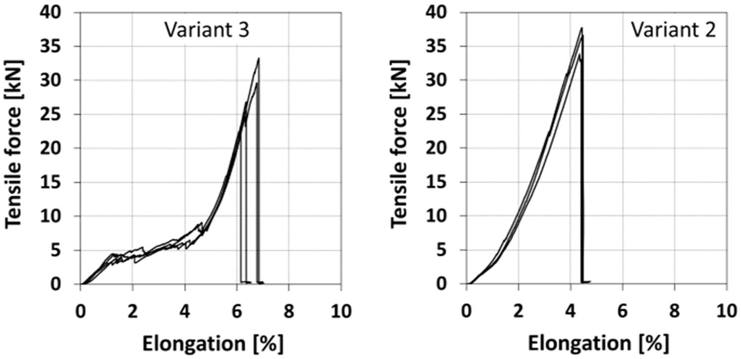
Force–elongation graphs of components reinforced with textile blanks of five samples of variants 2 and 3.
Due to the pronounced kink at the transition between the connection ring and the central web, the carbon rovings were exposed to an extraordinary transverse stress. As a proof, the calculated strength of the component fitted best to the test results using the transverse strength of the rovings. Up to 75% of the theoretical strength was achieved by the component. The remaining 25% would probably be lost due to the relatively strong ondulation of carbon roving.
Further investigations identified the influence of the type of fabric selvedge on the tear-out strength of the connection ring. Two components were manufactured for this purpose: one with a closed shuttle selvedge and the other one with a standard loom-like selvedge. This rapier woven selvedge with interrupted load trajectories leads to a significant reduction in the components’ strength. The connection ring then no longer cracks at the transition to the central web, but at the transition to the rapier selvedge. Figure 17 clearly illustrates the advantage of the closed selvedge made by shuttle weaving having over 50% higher tensile strength than the standard selvedge. Even more advantageous is the fact that the amount of carbon fibre used for the closed shuttle selvedge is approximately 30% lower than for the standard selvedge. It was proved very impressively that the shuttle-woven textile blanks for joint components have a significantly higher tear-out strength than those whose fabrics were produced with the ‘standard’ rapier weaving technology due to the closed fabric selvedge, and at the same time because of an additional closed reinforcement loop around the connection ring of the shuttle-woven textile.

Influence of the selvedge type (closed selvedge/standard selvedge) on the amount of carbon rovings needed and on the component’s strength.
Summary of component testing
Within the scope of the component tests, the failure behaviour of complex fabric constructions was analysed by tensile tests of six optimized component samples. In addition, tensile tests were carried out on original carbon rovings and on roving sections taken from fabric samples. The tensile strength of the rovings taken from the fabric sample was found to be reduced by 8%–from 2500 MPa for the original roving to 2300 MPa for rovings from the fabric.
Tensile tests of weave structures with interrupted load trajectories caused by a conventional weaving selvedge led to a significant reduction in component strength. The connection ring of the investigated rod did not break at the transition to the central web, but at the rapier selvedge.
Tensile tests of further consolidated components showed that the components made of 3D-woven structures with closed shuttle selvedges (variants 1, 2 and 3) break out at the transition from the connection ring to the central web. The reason, therefore, is a strongly bent yarn path of the carbon rovings which is already determined by the deliberately chosen shape of the forming tool. Additional stuffer wefts, that is, carbon rovings in the components’ load direction, if wrapped around the entire control rod (variants 1b and 1c), resulted in a corresponding increase in absolute component strength. The relative component strength remained constant. The integration of an additional, closed reinforcement loop around the connection ring (variants 1d) increased both the absolute and relative component strength. If the carbon weft threads or the entire fabric layers do not cross each other at the transition between connection ring and central web (variant 3), delamination of the component occurred in the area of the central web already at low tensile stress. With variant 3 it was shown that reinforcement structures made of stacked fabric layers without crossing the reinforcement threads at the transition from load introduction to the central web fail even at low loads due to delamination, that is, they have a lower modulus than components with ‘interwoven’ woven reinforcement structures and crossed reinforcement threads at the transition.
The novel weaving process presented here promotes a breakthrough for high-performance weave structures in the sustainable CFRP process chain. Higher mechanical performance of CFRP parts can be reached using the same mass of carbon fibres and matrix compared to standard parts due to different reinforcement strategies which are solely producible with 3D weaving equipment. These are interweave fabrics with additional straight reinforcement fibres (stuffer weft threads) and fibres dedicated to reinforce the ring connector for the selected sample geometry. Especially, the reinforcement of the ring showed to be very effective to improve the component’s tensile strength not only mechanically but also in terms of material use. The construction details and measured results of the tensile test are summarized in Table 1. At the same time, the fully automatic single-stage weaving process leads to a higher accuracy and repeatability of the textile blanks.
Technical guidelines for near-net-shape weave structures
Three technical guidelines can be derived from our results. In principle, reinforcements of rod structures comprising a central web joined to one or two connection rings (Figure 2) with tensile load are significantly improved by
Crosswise change of the fabric layers with basic weft threads at the transition between the connection ring and the central web (variants 1a, 1b, 1c, 1d and 2);
Straight reinforcement fibres which are floating without ondulation inside the interweave fabric (stuffer threads), whereby the entire component is looped around, as shown for variants 1b, 1c and 1d;
Reinforcement of the ring connector with an additional closed reinforcement loop of fibres around the connection ring (variant 1d).
Hence, from the technical point of view, the presented 3D weaving technology enables material-efficient weight-saving CFRP components with superior mechanical performance. Beyond that, a positive impact on economic and environmental aspects can be expected.
Impact on sustainability
In order to ensure a suitable comparison basis for the evaluation of the process chain of a novel 3D-woven reinforcement structure, a standardized process chain was opposed. As functional unit, the production of a rod structure, variant 1d (Table 1), was chosen. The examined comparison scenarios always refer to a final product with the same masses of carbon fibres and epoxy resin. This allows comparing two products with the same mass. Therefore, the life cycle analysis compares two parts of the same mass and shape but different technical functionalities as described in the technical sections above (Table 1). The evaluation was carried out within the system limits of cradle-to-gate. ‘The object of valuation is the partial product life cycle from the cultivation of raw materials to the company’s exit gate’. 16 Basis to examine the impact on sustainability was the DIN ISO 14051:2011 17 standardized methodology – MFCA. 18 MFCA focuses on the material, energetic and financial evaluation of defined material flows. 19 The method itself does not offer technical solutions, but is a valuable tool for the evaluation of various alternative process chains. 20 Incurred costs such as material, energy, labour costs and depreciation costs of machines are allocated to the modelled process steps. Equal to the Sankey diagram schematic, the MFCA method constitutes quantities as volume-proportional thick arrows.
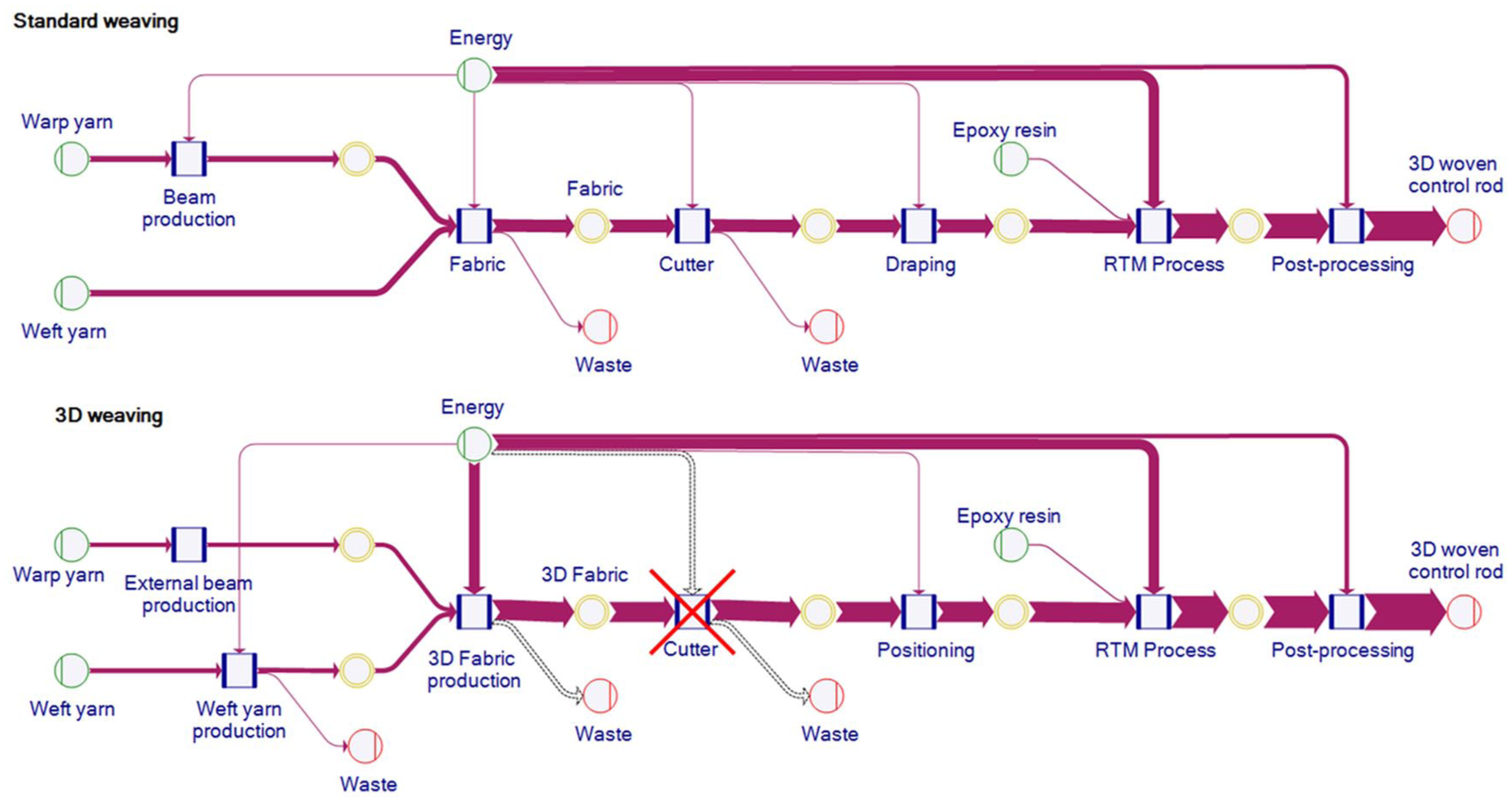
The manufacturing processes for the control rod (Figure 3) using the standard approach and the new 3D approach are shown in Figure 18. The main process steps comprised warp beam production, weaving, positioning, resin transfer moulding (RTM) and post-processing. The warp beam production for the 3D fabric was calculated as an external service, as specific know how is required and the technical data are not known in any detail. The warp beam production for the standard weaving is less complex. The input materials, which are represented by a green circle, include energies, the yarn material and the epoxy resin for the RTM process. The red circles with an inner line on the right side represent the product produced by the last process or waste flows within the process chain. Input materials are represented by green circles with an inner line on the left side. The yellow circles with thick edges represent intermediate products which are created within the process chain, for example, a woven fabric. At the end of the entire process chain, the two rod structures as described under functional unit are produced.

MFCA model of process chains for standard and 3D weaving process.
The main difference in the material flow resulted from the cutting process that is dispensable in the 3D weaving chain. Typical shares of trimming waste are around 20% to 50%. In the example described, a yarn waste of 25% was the basis for the standard process, while the new approach ensures zero waste of expensive carbon fibres. For the variants 2 and 3, the supporting structures show some minor waste of non-carbon weft fibres and carbon warp fibres. Also, the standard weaving process has around 1% waste rate, while the 3D weaving process is again a zero waste process. Therefore, the mass for weft yarn and warp yarn was increased accordingly in the standard process, as shown by the thicker arrows in the Sankey diagram represented in Figure 18.
Another relevant and obvious difference is the energy consumption of the two weaving processes. The main reason for this is the production time required, as shown in Figure 19. The time for the production of the warp beam is not known exactly because of missing technical data for the external service. However, this is neglectable for the comparison because it is less than 1 s for the warp unit required. The process time for 3D weaving presumed a weaving speed of 30 r/min. In this mapped scenario, the required period to produce a 3D-woven fabric with the Jacquard shuttle weaving technology was about 50 times higher compared to a standard weaving machine with a speed setting of 200 r/min. Both processes were based on an efficiency of 80%. This results in high energy consumption, high labour input and high depreciation costs.

Direct comparison of the production time required for each process step of the alternative process chains (product width 16 cm).
On the other side, the labour input for draping could be reduced dramatically because the 3D-woven fabric is produced as near-net shape. This study shows the strong dependency of several product and process parameters. There is not only one truth about the sustainability of the process chains. A sensitive product parameter is the component width. In Figure 20, the width of the product was varied in the dimensions 8, 16 and 32 cm. A process speed of 30 r/min was used as the basis for the 3D weaving process. The standard process runs with 200 r/min.

Total costs for the two process chains, for three different widths of the final product.
According to the graph in Figure 20, it can be stated that the total costs strongly depend on the component width. The material costs outlined above are growing directly proportional with the width for both variations, while the other cost categories have different relations. For the standard process, there is only a minor increase in costs for labour, depreciation and energy, while the 3D variation shows a proportional increase in these costs by around 50%. The main part of the difference resulted from the weaving costs, which are separately shown in Figure 21. These numbers clearly explain the different increasing factors for labour, depreciation and energy costs for both process chains. The values within the standard weaving process for energy, depreciation and labour costs are difficult to display on the scale of the y-axis due to their low values. Therefore, these bars are zoomed out as an integrated image.

Weaving costs of the process chains, with different speed settings of the 3D weaving machine.
The scenarios described so far covered variation of the component size and speed settings of the 3D weaving machine. For each process chain, there were modelled about 50 product and process parameters covering bill of material, efficiency factors, share of waste, labour effort, energy consumption and depreciation that are strongly linked. A rising speed of the 3D weaving machine, for example, leads to decreased costs for energy and depreciation, but will increase the labour costs, on the other hand, because there will be more disruptions with a high risk for the technical quality of the component. Thus, the question is not whether the new process is sustainable or not. The question to be answered is, therefore, which process and product parameters have to be achieved in order to perform economically sustainable.
To reply thereto, a life cycle assessment (LCA), based on the carbon footprint, was carried out to deconstruct the environmental side of sustainability in 3D weaving. The global warming potential (GWP), which was set as basis for assessing the environmental sustainability, simplifies LCA by referring to a single result value. 21 As part of the MFCA model, the GWP can be analysed in the same model as previously used. The total GWP in comparison for different variations, considering the component size 16 cm and different speed settings for the 3D weaving machine, is shown in Figure 22.

GWP of the complete alternative process chains, with different speed settings of the 3D weaving machine.
Electricity consumption is the key factor for the GWP of the 3D weaving chain. The advantage of lower material consumption can be overshadowed by the GWP resulting from electricity consumption. For this scenario, a GWP of 0.6 [kg CO2 eq/kWh] was used to represent the German electricity grid mix. The Sankey diagram representation for both processes (Figure 23) shows the big share of the GWP resulting from electricity consumption compared to the part resulting from the materials.
Sankey diagram representation of GWP resulting from material and electricity consumption.
Conclusion
Previous limitations in size, contour and in the 3D design of fibre orientation could be technologically solved with Jacquard shuttle weaving technology. With the application of the special weft insertion system, it is possible to form areas of different weft lengths with closed yarn paths. The weaving principle designed in this way resembles a 3D printing process in which the load-carrying reinforcing fibres in the reinforcement textile can be laid down and fixed close to the final contour in width, height and depth. This enables solidly formed CFRP reinforcement structures that can be flexibly designed in the spatial contour line. These structures incorporate woven elements designed for load trajectories and gradually follow the overall geometric structure in a multi-layer reinforcement structure. Thus, with the Jacquard shuttle weaving technology, components consisting of several parts can be replaced by one integral fabric section with improved performance potential. In doing so, joints and seams will be obsolete. A further exclusive advantage of the shuttle weaving technology over rapier weaving technology in terms of mechanical component properties is the closed fabric selvedge.
We could demonstrate that the novel weaving process results in material saving nearly without any waste of fibre material. This is a strong contribution to sustainable CFRP components. With the special weaving process, a higher performance of CFRP parts can be reached using the same mass of carbon fibres and matrix compared to standard parts.
The impact on sustainability of the new process was assessed by an MFCA analysis. There are strong dependencies of process and product parameters to be achieved in order to get an economical and sustainable product. Considering the excellent technical benchmarks of the rods investigated, there is an improved functionality that has additional benefits. Alternatively, the required functionality can be achieved with less material, therefore having better economic and environmental benchmarks.
Outlook
With interlock and interweave bindings, CFRP component properties such as dimensional stability, compactness and bending stiffness can be adjusted according to the requirements. Delamination at critical junctions can be prevented by engineered yarn paths of the weave and by crossing reinforcement threads between layers. The insertion of looping and crossing reinforcement threads, for example, closed reinforcement loops, allows an increase in mechanical properties of the CFRP component; especially, the delamination in critical areas of transverse loads can be reduced effectively. Continuous load trajectories increase component strength, so 3D weaving contributes to near-net-shape reinforcement structures that have load-carrying fibres where they are needed. Due to the right material at the right place by design, wastage of precious fibre material is reduced. Therefore, an important key result is the knowledge of the right way to create a digital model of the anticipated reinforcement structure. Not only the lightweight products made of reinforcement structures but also the industrial production process applied become more sustainable with 3D weaving.
Footnotes
Declaration of conflicting interests
The author(s) declared no potential conflicts of interest with respect to the research, authorship, and/or publication of this article.
Funding
The author(s) disclosed receipt of the following financial support for the research, authorship, and/or publication of this article: The IGF-Project 18719 N of the research association Forschungskuratorium Textil e.V., Reinhardtstraße 12-14, Berlin, Germany was granted by the AiF in the framework of the programme to promote the Industrial Community Research (IGF) by the German Federal Ministry for economy and energy on the basis of a resolution of the German Bundestag.