
Abstract
Despite the fact that tensile behavior of woven fabrics has been previously explored, the nonisotropic material qualities of fabrics can be considered from various points of view. From this perspective, this study is carried out to comprehensively inspect the tensile behavior of woven fabrics. Since worsted fabrics are considered in outwear clothing and their extension under low loads determines their shaping on the body, the extension behavior of the worsted woven fabrics in various directions was probed thoroughly. It was found that fabric stress variations in terms of time in all directions trace in a parabolic manner but the shape of the curve (open or close form) depends on the fabric direction. The above mentioned phenomenon is related to weft and warp yarn crimps and their contribution to tolerating the tensile load. In all fabric directions, it is possible to identify the tensile behavior index, which is the time of change in the fabric’s tensile behavior. The value of tensile behavior index against fabric direction follows a sinusoidal function, and it is affected by fabric weave structure and density.
Introduction
Fabric’s mechanical properties have an important influence on fabric behavior during the manufacture and final product end uses. Thus, it is necessary to study its fundamental and practical implications for the specification of the mechanical properties of woven fabric structures. One of the most prominent mechanical properties of woven fabrics is their tensile behavior that has been studied in some detail during the past few years, but due to the diversity of the various aspects of this phenomenon, there is still a need to look over this fact thoroughly and seek novel findings.
In this area of interest, Seo et al. carried out a study on the mechanisms of tensile failure of staple yarns during uniaxial tensioning, as in a conventional ravel strip test. It was concluded that there are numerous isolated yarn failures and in many cases the magnitudes of the load drop exceeded the average single yarn breaking strength. The mechanism of yarn failure in fabric subjected to uniaxial tensile testing is strongly influenced by fabric geometry at the instant of failure and by yarn properties both mechanically and topologically. 1 Realff used experimental methods to present fabric local deformation during uniaxial tensile loading of woven fabrics. It was inspected that changes in yarn curvature and cross section are along with the stress–strain response of the fabric. It was found that fabric response depends on its structure and constituent yarn properties. 2 In a study conducted by Pan, it was revealed that when a fabric is under uniaxial or biaxial tension, the yarn–yarn interactions at the crossing points are found to consist of two components, a pressure-independent adhesive component and a pressure-dependent frictional component, the latter of which is proven to be dominant. On the basis of the analysis, the critical length of the yarn in the fragmentation process during fabric extension was defined and calculated. 3 Kothari and Chitale observed the effect of increase in pick density on the strength and extension behavior of the fabric in both warp and weft directions. Warp-way fabric strength decreases, while weft-way strength increases with the increase in pick density. It was also indicated that fabric strength has an inverse relationship with crimp. 4 Gu stated that fiber characters play an important role in estimating woven fabric tensile strength. It was found that the tensile strength is greater than the total strength of the yarns in the testing direction. 5 Majumdar et al. predicted the tensile strength of plain woven fabrics using two empirical modeling methods, namely artificial neural network (ANN) and linear regression. The trend analysis of the developed ANN model shows that the model is able to reveal the effect of various input parameters on the fabric strength. 6 Banerjee et al. studied the interdependence between the sett, construction, and tensile behavior of woven fabrics. Their outcome reveals that tensile behavior of a fabric and particularly yarn strength usage is highly dependent on the crimp value in yarns that are located along the extension and transverse direction, the magnitude of crimp interchange, and its ease and the number and distribution of the interlacement points as well as radial forces of compression at these locations. 7 Malik et al. 8 also presented two ANN models to predict warp and weft-wise tensile strength of polyester/cotton-blended fabrics. Finally, Hosseini et al. considered the role of the nonlinear region of load–extension curve of woven fabric to be important in the tensile extension behavior of fabric during wear and determined its deformation. It was declared that the fabric’s geometry such as floating and diagonal parts of the yarns and yarn crimp affects fabric modulus and Poisson’s ratio in the nonlinear region. 9 Xu et al. 10 developed a two-scale micromechanical model to forecast the stress relaxation modulus of polymer matrix composite, which was reinforced with a plain weave T300 carbon fabric.
Extension properties of woven fabrics depend on fabric structural parameters such as warp and weft-interlacing pattern (weave structure). Since the fabric is not an isotropic material, its mechanical behavior changes, as the direction of load application alters. In this study, an attempt is made to analyze the influence of fabric parameters such as weave structure and fabric density on fabric tensile performance. Besides, it is important to study the variation and trend of extension parameters against fabric direction. Hence, the aim of this investigation is to measure and analyze fabric tensile factors in different directions and present a precise function for the prediction of fabric tensile behavior in various directions.
Experimental work
Materials
This study was carried out to explore detailed information about the tensile behavior of worsted suit fabrics in several directions of the specimen. In this regard, eight various worsted woven fabrics with different weave structures and weft densities are used. All fabric samples were produced from similar warp and weft yarns and only the weave structure and yarn density of fabrics were altered. Fabric yarns in both warp and weft directions were 40/2 N m (twist factor αm = 70) and comprised 45/55 wool–polyester. The characteristics of these fabrics are shown in Table 1.
Fabric characteristics.

Test method and sample preparation
In order to measure and analyze the fabric tensile parameters by considering the fabric direction, it is necessary to prepare the samples in a specific manner. Since woven fabrics are nonisotropic materials, their mechanical properties such as extension behavior are not similar in different directions, and so they should be quantified along various angles of fabrics. In this study, the tensile behavior of the fabric was investigated in various directions as follows: 0°, 10°, 20°, 30°, 40°, 45°, 50°, 60°, 70°, 80°, and 90°. It should be included that 0° and 90° imply the warp and weft directions, respectively. It is clear that the degree interval is 10°. However, fabric properties are measured at 45° as well, since this direction is a prominent position and kind of turning point in fabric mechanical properties. To prepare the samples in various directions, the warp yarns were taken as the main direction (0°) and then the fabrics were cut according to the desired angle in relation to the warp position. The values for fabric extension parameters were obtained using five samples.
To probe extension behavior of the fabric, the tensile testing machine (Instron 5566) was used. Gauge length was 100 mm, and a pre-load equal to 20% of the fabric weight was used to acquire more accurate results. The extension rate was 5 mm/min, and all specimens were extended to the stress point of 120 cN/cm.
Results and discussion
Investigation of the relation between stress and time
Since fabric is a nonisotropic material, it is expected that its extension behavior under tensile loads changes according to the fabric direction. The diagram of stress in various directions is drawn for all fabric samples. Due to the fact that all samples follow the same trend, the curves obtained for sample F2 are presented as an instance. According to the curve-fitting procedure, all samples pursue a parabolic function (Figure 1). It should be noted that in this study fabric’s tensile property is evaluated up to the load value of 500 cN, which is related to the fabric deformation under small tensile loading. This limit of force is usually applied on the fabrics during wear. The result of the curve-fitting process confirms this finding with a high correlation coefficient (more than 0.99). This means that tensile stress can be stated as a function of time
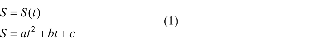
The values of

Extension behavior of fabric in each direction in terms of time.
The result of curve-fitting process for sample F2.
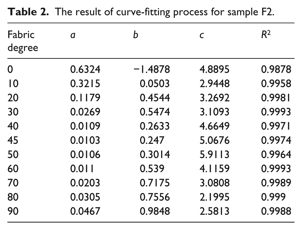
It can be seen that the value of constant

Bearing in mind the properties of parabolic curve, when the value of

Tensile load and its components on the fabric strip.
According to Figure 2, the tensile load which is tolerated by the fabric in each direction (warp and weft yarn cooperation in this matter) can be divided into its components, in the following way
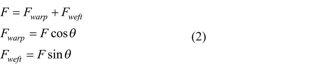
The value of

Load-bearing capacity of warp and weft yarns in terms of fabric direction.
When the fabric is extended at 0°, the load is exerted to the warp yarn axis. As a result, in the first stage, the warp yarn’s decrimping occurs and after that yarns endure the tensile load, which leads to yarn extension that needs higher tensile loads. However, when the fabric is extended in the 45° direction, the load is applied on both weft and warp yarns similarly, which are located diagonally to the load direction. Therefore, the load is gone for the decrimping of weft and warp yarns and the fabric strip extends easily even under lower loads. Hence, its tensile stress–time curve is open. Moreover, as it is shown in Table 2, the fabric’s extensibility at 10° and 20° requires more tensile force compared to 90°, which is the weft direction. Thus, it can be declared that by increasing the value of
The asymmetric behavior of fabric under tensile loads
According to Figure 4, by comparing the tensile behavior in various directions, it was observed that fabric behavior from 0° to 45° is dissimilar to that of 45°–90°. The tensile curves in the region from 45° to 90° are closer to each other in comparison with the curve from 0° to 45°.

Extension behavior of fabric in each direction in terms of time: (a) from 0° to 45° and (b) from 45° to 90°.
This behavior is the result of warp and weft yarn’s orientation to the direction of tensile load in each sample. When a woven fabric is extended, the tensile process consists of the yarn’s decrimping and simultaneously crimp interchange between crossing yarns, and finally the yarn’s pure elongation. Suppose that a fabric with plain weave is extended in various directions as it is shown in Figure 5. In this figure, the warp and weft yarns are presented in black and white colors, respectively. As it was mentioned previously, it should be noted that the sample direction is the angle between loading direction (as it is displayed in Figure 5) and the warp yarns that are shown in black color. The values of different angles are also presented in Figure 5. When the specimen degree is 0 (fabric is extended in the warp direction), it means that warp yarns are carrying the tensile load. Tensile load is assigned for decrimping of warp yarns and it is along with the warp yarn’s axis. By moving from warp to weft direction, when the sample’s degree increases, not only warp yarns but also weft yarns contribute to tolerating the tensile load. But in this condition, not only is the load in the direction of warp and weft yarn axis but also a longer time is demanded for the complete yarn decrimping procedure. On the contrary, the tensile load is required for decrimping of both warp and weft yarns. This means that the sample will extend easily by applying lower loads, and it takes more time to finish the decrimping procedure and start the pure extension of warp and weft yarns along their axis direction.

The orientation of warp and weft yarns in terms of fabric direction.
The other point that should be considered is the difference between fabric tensile behavior from 0° to 45° and from 45° to 90°, which is referred to as the asymmetric tensile behavior of fabric in this article. This phenomenon is related to the warp and weft yarn’s crimp and the percentage of their contribution in bearing the tensile load in each sample. As it is shown in Figure 6, when the sample direction changes from 0° to 45°, the angle between warp yarns and load direction increases from 0° to 45°. This means that the warp yarn involvement in carrying the tensile load reduces but an increment in the role of weft yarns occurs. However, in this range (Figure 6(a)), the warp yarns have more contribution in tolerating the tensile load until 45° in which both warp and weft yarns have the same part in the load bearing.

Asymmetric behavior of tensile load bearing: (a) from 0° to 45° and (b) from 45° to 90°.
On the contrary, when the fabric’s direction varies from 45° to 90° (Figure 6(b)), the weft yarn’s contribution in the tensile load direction increases. Since the weft yarn’s crimp is higher than that of warp yarns (Table 1), by a constant tensile force, the fabric can extend more easily. Hence, it can be said that when the contribution of weft yarns is more in tolerating the tensile load, the fabric extension becomes more straightforward.
Determination of turning point in fabric tensile behavior
According to Figure 1, in each fabric direction, the extension process can be divided into two sections. In the first section, lower levels of load are required for fabric extension. This is because in this stage of the test, the tensile load is used to decrimp the yarns of the samples and after that in the second section higher loads are gone for pure extension of yarns in the fabric until the breaking point. An attempt is made to find the time of transition between these two stages.
To this end, a tangent line is drawn (Figure 7) on the first and last parts of the stress–time curve. The intersection point of these two lines can be regarded as a turning point of the fabric tensile behavior, which is called the tensile behavior index (TBI) in this study. TBI approximately introduces the time at which the decrimping process quits and the yarn’s pure extension commences, and it is applicable at low-level tensile-loading processes. This property is in accordance with the role of warp and weft yarns in handling the process of decrimping, as it is shown in Figure 6.

Determining the time of TBI.
The magnitude of TBI is calculated for all samples in each direction according to the method explained in Figure and its results are shown in Table 3. For better illustration of the trend of TBI variations in terms of fabric direction, the TBI changes considering fabric direction are drawn and explained in Figure 8 for all samples.
The value of TBI (s) for various samples.

TBI: tensile behavior index.

Variation of TBI in terms of fabric direction.
As it is presented in Figure 8, for all samples the value of TBI increased from 0° to 45°; however, it reduced from 45° to 90°. Increment of TBI reveals that the time assigned for lower load levels increases. For directions below 45°, the magnitude of TBI is less, which is related to weft and warp yarn’s crimp and their participation in the tensile load axis.
Another point that should be noted is that the trend of TBI is opposite to the constant

This outcome reveals that the curves with lower TBI are more compressed.
According to Figure 8, it seems that there is a sinusoidal relation between TBI and fabric direction. In order to probe this relation in more detail, the curve-fitting toolbox of the MATLAB software was used. The consequence of the curve-fitting process confirms this relation as follows

where
The results of curve fitting are presented in Figure 9. This equation can be utilized for predicting the tensile behavior of fabrics in various directions.

The result of curve fitting for the relation between TBI and fabric direction.
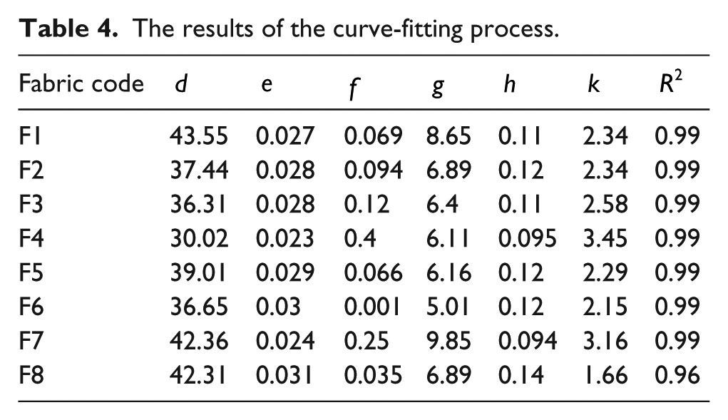
The high correlation coefficient of the fitting procedure supports the resultant function. The values of constants are shown in Table 4.
The results of the curve-fitting process.
The effect of shear modulus on the TBI
When the fabric is extended in various directions, especially at the angles except the warp and weft directions, the constituent yarns in the loading path tend to move toward each other and shear deformation occurs. In fact in this situation, in-plane rotation of the yarns at the crossover of the weave happens along with yarn slippage at the connecting points of warp and weft yarns.
In this study, in order to measure the shear rigidity of the fabrics, the bias extension test (at the degree of 45 in relation to the warp direction) was carried out, and the shear stress and strain were calculated according to the research by Spivak and Treloar. 11 The shear rigidity is reported where the TBI happened, actually at the time at which nearly the decrimping process stops and the yarns undergo pure extension. The values of shear stress (R), shear strain (ε), and shear rigidity (G) at the TBI point are shown in Table 5.
Shear properties and the crimp at 45° direction.

Considering the shear rigidity obtained for various sample groups, it was concluded that this property is affected by the fabric structural parameters.
As it is clear in Figure 10, by increasing the weft density of the fabrics, the shear rigidity of the fabric increases. Among various weave structures that were used in this study, Twill 2/1 had the highest shear rigidity followed by Twill 3/1 and Hopsack 2/2. The lowest shear rigidity belongs to Twill 3/3. The abovementioned trend can be interpreted by considering the firmness of the fabric. It should be noted that any structural alteration that leads to the difficulty of yarn displacement in the structure causes harder shear deformation. Statistical analysis of the results confirmed the effect of fabric structural parameters on shear (significance level of 0.05).

Effect of fabric structural properties on shear rigidity.
Moreover, as it is shown in Figure 11, the shear rigidity can affect the TBI times negatively. By increasing the shear rigidity of the fabric the value of TBI diminishes. This fact points to this occurrence that when it becomes hard for the yarns located in the fabric structure to slip toward each other, the time at which the pure elongation of the constituent yarns starts (TBI) will be reached sooner.
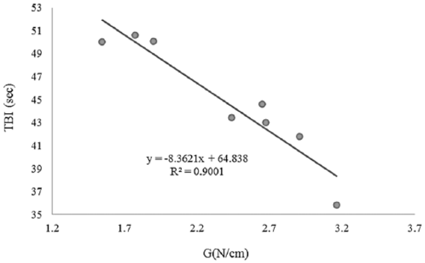
The relation between TBI and shear rigidity.
Thus, it can be declared that besides the effect of the decrimping procedure, the shear rigidity of the fabric influences the value of TBI. This case was specifically studied for the direction of 45° where the shear rigidity of the fabric in a bias extension test is estimated.
The contribution of warp and weft yarns’ crimp (Cθ) in each direction of test can be calculated as

where C1 and C2 are the warp and weft crimps, respectively. The values of C45 for all sample groups are listed in Table 5.
The linear regression analysis for the investigation of the effect of C45 and shear modulus on the TBI factor is given below

The linear regression coefficients were obtained with R2 = 0.904 (significance level of 0.05).
As it is apparent in the linear regression equation, both mentioned factors (C45 and shear modulus) influence the TBI significantly. By an increase in the value of C45, TBI increases, while a growth in the shear rigidity of the fabric leads to reduction in TBI.
The relation between TBI and weave structure and fabric density
Since TBI is an index of fabric tensile behavior and fabric properties are influenced by its structural parameters, in this part an attempt is made to explore this relation. As it is shown in Figure 12 (since the values of TBI follow the same trend in various fabric directions, the graph of TBI in terms of weave structure and fabric density is noticed in the direction of 45°), the fabric’s weave pattern has a considerable effect on the TBI. It can be noticed that the value of TBI is higher in Twill 3/3 and Hopsack 2/2; however, it reduces in Twill 3/1 and Twill 2/1. This finding is related to the firmness of fabric structure. When the fabric has a flexible weave with more floating yarns, under tensile load it can extend more easily which leads to an increase in the value of TBI. This hypothesis is valid for fabric density as well. When fabric density increases, the firmness of the fabric increases and it is hard to extend the fabric under tensile load.
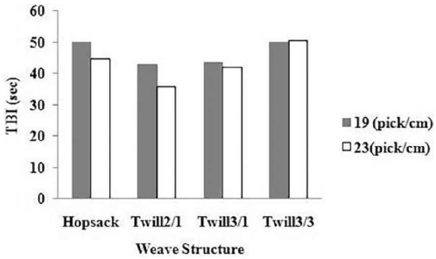
The effect of weave structure and fabric density on TBI.
In order to analyze the concluded data statistically, SPSS software was used. The results revealed that at the 95% confidence interval, the effect of weft density and weave structure is significant on the tensile behavior of woven fabrics.
Conclusion
The fabric’s tensile behavior is one of the prominent mechanical properties of woven fabrics, which affects their application in various end uses. Since woven fabric is a nonisotropic material, its tensile behavior changes in different directions of the fabric. Hence, in this study, the tensile characteristics of woven fabric in a series of fabric directions were analyzed.
In the range of loads used in this work, the diagram of stress per time follows a parabolic function. This trend was observed in all directions of the test. It was revealed that the value of the coefficient
It was also concluded that the rate of extension in various directions of the fabric depends on the percentages of contribution of weft and warp yarns in tolerating the tensile load. In directions where the duration of decrimping stage increases, the whole extensibility of the fabric increases.
In this article, a new tensile parameter named TBI was also introduced for interpreting the tensile behavior of woven fabrics. In fact, this factor points to the number of transitions between two stages of fabric extension (decrimping zone and pure extension of yarns). From 0° to 45°, the value of TBI increases gradually and hits the peak at 45°, and the value of TBI decreases from 45° to 90°. Using the MATLAB curve-fitting toolbox, it was found that the trend of TBI against fabric direction pursues a sinusoidal function. This function can be utilized to forecast the tensile characteristic of woven fabrics in different directions.
It was concluded that the value of TBI is affected by the contribution of warp and weft yarn crimp and also the shear rigidity of the fabric in each direction of load exertion.
Analysis of the results revealed that at the 95% confidence interval, the effect of weave structure and weft density is significant on the value of TBI. Among the structures that were tested in this study, Twill 3/3 had the highest value of TBI and thus the easiest extensibility, while Twill 2/1 had the lowest value of TBI. It was also shown that by increasing the density of the fabric, the value of TBI decreases and extensibility of the fabric becomes harder.
Footnotes
Declaration of conflicting interests
The author(s) declared no potential conflicts of interest with respect to the research, authorship, and/or publication of this article.
Funding
The author(s) received no financial support for the research, authorship, and/or publication of this article.