
Abstract
To study the reinforcement effect of textile-reinforced concrete (TRC) on concrete structures in a marine environment, a four-point bending loading method was used for graded loading to analyze the influence of the dry–wet cycle number, the reinforcement method, and chopped fiber addition on the flexural properties of load-holding reinforced concrete beams reinforced with textile-reinforced concrete. The results show that with the increase of dry–wet cycle numbers, the crack width and deflection of beams develop faster and the bearing capacity decreases. The performance of the prefabricated textile-reinforced concrete plate is close to that of a cast-in-place textile-reinforced concrete in limiting crack, bearing capacity, and deflection deformation. The addition of chopped fibers in fine-grained concrete can improve the reinforcement effect of textile-reinforced concrete. Based on the experimental results and referring to the relevant design codes and literature, the calculation formula of the bearing capacity of TRC-strengthened beam with a secondary load is established, and the calculated values are in good agreement with the actual values.
Keywords
Introduction
Damage of concrete structures caused by insufficient durability is very common, especially the durability problem of marine concrete structures, which shows a yearly increasing trend. Most of these concrete structures are in a chloride corrosion environment, and with the increase of service time, the mechanical and overall properties deteriorate, damaging, or even destroying, the structures. 1 Therefore, the reinforcement and repair of concrete structures are necessary.
Fiber-reinforced polymer (FRP) is a typically used reinforcement material. Deng et al. 2 used infrared detection technology to record the interfacial fatigue behaviors between FRP and concrete, and the result showed good interfacial anti-fatigue properties of FRP. Chotickai and Somana 3 showed that a chlorine salt dry–wet cycle environment had no significant effect on the bond strength of carbon fiber–reinforced polymer (CFRP) composite materials and the tensile side of the concrete beam. Zhu et al. 4 carried out an experimental study on the bending capacity of reinforced concrete (RC) beams strengthened with CFRP considering secondary load, and the result showed that the flexural capacity of beams, strengthened with CFRP after damage, can also be improved significantly.
FRP can have a better reinforcement effect, but there are also some limitations, such as poor high-temperature resistance and fire resistance and difficulty working on wet concrete surfaces. The emergence of cement-based reinforcement materials can solve these problems better. 5 Textile-reinforced concrete is a new type of cement-based composite material, which has good coordination with old concrete, and it can hardly change the original component section size when used to reinforce a structure. 6 These characteristics provide TRC with a broad application prospect in the repair and reinforcement of marine concrete structures.
At present, scholars further research TRC-strengthened flexural members. The study of Larbi et al. 7 showed that TRC could improve the bearing capacity and crack-limiting ability of beams to a certain extent, but could not provide significant gain in terms of ductility. Contamine and Larbi 8 developed a kind of TRC material suitable for repairing reinforced concrete beams by in situ contact molding, and the composite is made of a polymer-modified cementitious matrix reinforced with grids of alkali-resistant (AR) glass yarns. The results from Verbruggen et al. 9 showed that the TRC reinforcement layer had good crack bridging ability and its application on the full width of a beam was beneficial to bearing capacity improvement and crack width limitation. The experimental results of Truong et al. 10 showed that the reinforcement effect of TRC was good and that it would not be affected by the precracking of the beam. Xu et al. 11 studied the mechanical properties of TRC-strengthened beams with a secondary load under conventional conditions. The experimental results showed that the increased amplitude of the ultimate load of the reinforced beams decreased with the damage degree increase and that the TRC thin plate could better limit crack development, showing good toughness. Furthermore, the research of Gopinath et al. 12 showed that TRC was an effective method for reinforcing the tensile zone of beams under chloride erosion. The results of Yin et al. 13 and Sheng et al. 14 showed that the bonding performance between TRC and old concrete would be affected by the coupling effect of load and the dry–wet cycle with chloride; furthermore, TRC still played a better role in improving the crack development and fatigue life of beams.
However, the actual structure is generally sustaining a load when reinforced, and research on TRC-strengthened beams with a secondary load under an erosion environment is less at present, and so further study is needed. On the basis of summarizing the previous research and combining with engineering practice, this article studies a TRC-strengthened beam with a secondary load under a marine environment and considers the influence of the dry–wet cycle number, reinforcement method, and chopped fiber addition on the flexural properties of load-holding RC beams reinforced with TRC.
General experimental situation
Specimen design
A total of six beams, H1–H6, were made in the experiment. The size of the unreinforced beam was 100 mm × 190 mm × 1200 mm, the size of the reinforced beam was 100 mm × 200 mm × 1200 mm (the thickness of two textile layers was 10 mm), and the thickness of the protective layer was 20 mm. The detailed reinforcement is shown in Figure 1, and the detailed information of the beam is shown in Table 1.

Size, reinforcement, and measurement equipment layout.
Information on the specimens.

PVA: polyvinyl alcohol; AR: alkali resistant.
Concrete
In the experiment, C40 concrete was used. The mix proportion is cement:water:medium sand:gravel:water reducer = 415:161:643:1181:2.85, respectively. The average strength measured after curing the concrete cube standard test block of 150 mm × 150 mm × 150 mm for 28 days was 45.29 MPa.
Steel bar
Two main reinforcements were arranged in the tensile area; the grade was HRB400, the diameter was 12 mm, and the yield strength measured by tensile test was 518 MPa. Erection bars were two steel bars with a diameter of 12 mm and grade of HPB300, and the stirrups were steel bars with a diameter of 6.5 mm and grade of HPB300. The stirrup spacing of shear bending section was 60 mm and that of the pure bending section was 150 mm, as shown in Figure 1.
Textile
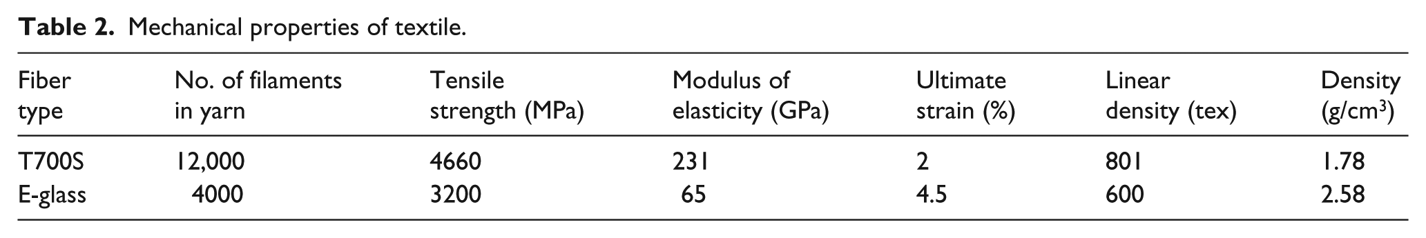
The experiment used the textile adopted in the literature; 6 the carbon fiber bundle was used in the weft direction (enhancement direction) and the glass fiber bundle was used in the warp direction (fixation direction). The spacing of the fiber bundle was 10 mm × 10 mm. The mechanical properties are shown in Table 2. The literature 6 suggested that the textile impregnated with epoxy resin and covered with sand had better effective confining ability, which could make full use of the crack-limiting and enhancement effect of the TRC reinforcement layer. In this experiment, all textiles were impregnated with epoxy resin and covered with sand. The weft direction was the main force direction, and so this article only provided the physical and mechanical parameters of the carbon yarn, which are shown in Table 3.
Mechanical properties of textile.
Mechanical properties of weft carbon yarn with epoxy resin impregnated.

Fine-grained concrete
The mix proportion of fine-grained concrete provided by the literature 13 was cement:fly ash:silica fume:water:fine sand:coarse sand:water reducer = 475:168:35:262:460:920:9.1, respectively. The average strength measured after curing the concrete cube standard test block of 70.7 mm × 70.7 mm × 70.7 mm for 28 days was 52.5 MPa.
Chopped fiber
Polyvinyl alcohol (PVA) and AR-glass chopped fiber were used in the experiment, and the geometric parameters and mechanical properties are shown in Table 4.
Properties and geometric parameters of chopped fibers.

PVA: polyvinyl alcohol; AR: alkali resistant.
Reinforcement scheme
According to the reinforcement form of TRC, the scheme can be divided into the following two methods: cast-in-place and prefabricated reinforcement. The cast-in-place TRC can be divided into the following steps: first, the bottom surface of the beam was roughened and cleaned; roughening was done to increase the surface roughness, thereby enhancing the bonding performance between TRC and old concrete. Second, the beam was subjected to four-point bending loading with a load ratio of 0.2 (the load ratio is the ratio of the sustained load to the ultimate load of the unreinforced beam, which was obtained by calculating). 14 Third, planks were placed on both sides of the beam and fixed with fixtures, keeping the edges of planks flush with the beam surface. Fourth, fine-grained concrete of 2–3 mm was evenly smeared on the surface of old concrete, and then, textile was laid and fixed on both sides of the planks using 3-mm wooden strip for controlling the total thickness of the reinforcement layer to be 10 mm. Fifth, the third step was repeated and the surface of the reinforcement layer was smoothed evenly. After reinforcement was completed, the beam bottom was covered with a plank, and the fixtures were used to tighten the connection to prevent falling of the reinforcement layer due to the weight of TRC, which would affect the interfacial performance between TRC and old concrete. The reinforcement diagram is shown in Figure 2.

Reinforcement diagram: (a) picture of casing and (b) casing sketch under sustained load.
The prefabricated reinforcement can be divided into the following steps: first, the TRC reinforcement layer was prefabricated in advance, and the thickness of the prefabricated panel was controlled to be approximately 8 mm. The first, second, and third steps were then repeated for the cast-in-place reinforcement. Then, 2–3 mm of fine-grained concrete was evenly smeared on the surface of old concrete and the prefabricated panel was laid.
Chloride environment
The sustained load was removed after TRC was cured for 28 days under room temperature and the humidity of no less than 95%. Then, the marine environment was simulated, and a dry–wet cycle with chloride salt was carried out. The simulation system is as follows: 13 after immersion in 5% sodium chloride solution for 12 h under room temperature and the humidity of 45%–75%, the chloride salt solution was drained and the specimens were dried for 12 h (using fans for assistance, which is equivalent to simulate sea breeze). This was a complete dry–wet cycle lasting for 24 h.
Loading mode and test content
After the specimens dried completely, the four-point bending loading mode was adopted. The upper part of the jack was a pressure sensor, and the loaded values were read through the display. To verify the plane section assumption, concrete strain gauges were attached to the mid-span part of the specimen; one gauge was installed on the top and four gauges were installed on the side at the distances of 40, 80, 120, and 160 mm from the top of the beam. The mid-span deflection and the fulcrum deformation were measured via a displacement meter. In addition, the steel strain gauges were attached to the middle part of the longitudinal tension reinforcement for judging the yield of the steel bar. During loading, the loading grade was 5 kN, and at 3–5 min after each loading, cracks were observed and the maximum crack width was measured. The DH-3816 static acquisition equipment produced by Jiangsu Donghua Test Co., Ltd. was used for the data acquisition. The crack width was measured via a crack width tester produced by Beijing Earth Long Science and Technology Co., Ltd., with an accuracy of 0.02 mm.
Experimental results and analysis
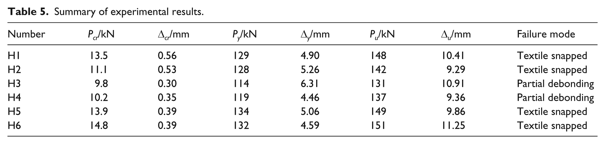
The cracking load Pcr, yield load Py, and ultimate load Pu of the specimens are summarized in Table 5. Δcr, Δy, and Δu are the mid-span deflections corresponding to the cracking, yield, and ultimate load, respectively.
Summary of experimental results.
Failure characteristics and crack analysis
In the experiment, the textile of all beams had tensile failure, and the concrete in the compression zone was finally crushed. There are two failure modes, including TRC and old concrete bonded together and cracks generated along the longitudinal steel bars. This is due to the good bonding between TRC and the old concrete, which is better than the bonding between the old concrete and steel bars; the yield of the steel bars also led to the weakening of the latter, as shown in Figure 3(a). Another failure mode is the partial debonding of TRC, as shown in Figure 3(b). That is because, on one hand, the load before reinforcement makes the beams have deflection deformation, and the beams have certain deformation recovery after unloading, which causes certain interaction between TRC and the old concrete, leading to the shearing force which weakens the interfacial bonding performance. On the other hand, the interfacial performance is reduced due to the effect of the dry–wet cycle and chloride corrosion, which make the interface between TRC and old concrete generate more microcrack.

Failure modes of beams: (a) textile snapped and (b) partial debonding.
Different dry–wet cycle numbers
Beams H1 and H2 have the failure mode shown in Figure 3(a), while beam H3 has the failure mode shown in Figure 3(b). The partial debonding of beam H3 may be due to the increase of the dry–wet cycle numbers, which leads to the increase of holes and microcracks in the interfacial microstructure between TRC and the old concrete, decreasing the interfacial bonding performance. Meanwhile, chlorine salt crystallizes and corrosion products are produced in the concrete. With the increase of the dry–wet cycle numbers, the corrosion time increases and the corrosion products increase, resulting in internal expansion stress, which causes deterioration of the concrete performance. 15 As seen from Figure 4(a), the crack width development of the three beams is almost the same before a certain load, and in the later stage, due to the partial debonding of beam H3, the crack-limiting performance of TRC is reduced, making the crack develop faster and with a width larger in the later stage.

Load-maximum crack width diagram of beams: (a) H1, H2, H3 and H4 and (b) H2, H5 and H6.
Different reinforcement methods
Beam H4 has the failure mode shown in Figure 3(b). On one hand, because the beam was reinforced with a sustaining load, it has a certain deflection before strengthening, and the prefabricated board is a whole, and so the interfacial bonding between TRC and the old concrete is damaged after unloading. On the other hand, the surface roughness of the prefabricated TRC board is lower, which reduces the interfacial bite force. The damage accumulates after the dry–wet cycle and chloride corrosion, affecting the interfacial performance to a certain extent. It can be seen from Figure 4(a) that the crack-limiting ability of the prefabricated panel reinforced beam is similar to the cast-in-place reinforced beam; however, in the later stage of loading, the control ability of prefabricated panel to crack decreases and the crack develops faster a little. On the whole, however, the prefabricated TRC board can also play a good role in structural reinforcement.
Chopped fiber content
Beams H5 and H6 have the failure mode shown in Figure 3(a). As seen from Figure 4(b), at the same loading level, the maximum crack width of beams H5 and H6 is smaller than that of beam H2, and the crack development is slower. This result indicates that the crack-limiting ability of beams H5 and H6 is better than that of H2, especially in the later stage of loading. This is because the fiber plays a bridge role, which contributes to the stress transfer at the surface between textile and fine-grained concrete and reduces the stress concentration at the crack tip, limiting the concrete cracking. Moreover, the fiber addition can improve the pore structure and reduce the internal porosity of the concrete, which makes its structure denser; therefore, the resistance of TRC to chloride ion permeation is improved, alleviating the deterioration caused by chloride erosion. 16
Bearing capacity analysis
Different dry–wet cycle numbers
With the increase of dry–wet cycle numbers, the cracking, yield, and ultimate load of beams decrease, as shown in Table 5. Compared with beam H1, the cracking load of beam H3 decreases by 27.41%, the yield load decreases by 11.63%, and the ultimate load decreases by 11.49%. On one hand, as described in section “Different dry–wet cycle numbers” under “Failure characteristics and crack analysis,” with the increase of dry–wet cycle numbers, the interfacial bonding performance between TRC and old concrete decreases. On the other hand, microcracks generate inside the concrete when the beam has a reinforced sustaining load, which promotes the penetration and erosion of chloride ions, making the concrete performance decrease; therefore, the bearing capacity of reinforced beam is affected. From the perspective of the failure mode of beam H3, the partial debonding causes the TRC reinforcement layer to not play its full role, affecting the improvement of bearing capacity.
Different reinforcement methods
It can be seen from Table 5 that, compared with beam H2, the cracking load of beam H4 decreases by 8.11%, the yield load decreases by 7.03%, and the ultimate load decreases by 3.52%. As explained in section “Different reinforcement methods” under “Failure characteristics and crack analysis,” the unloading after sustaining load has a certain influence on the interfacial bonding performance between a prefabricated TRC panel and old concrete, and the dry–wet cycle with chloride weakens the bonding force further, decreasing the reinforcement effect of TRC to some extent. It can also be seen from the failure mode of beam H4 that, in the later stage, the textile is snapped and then the middle part exfoliates, which indicates that the bonding performance is worse than that of cast-in-place TRC, decreasing the ultimate bearing capacity of beam H4.
Chopped fiber content
As shown in Table 5, the cracking, yield, and ultimate load of reinforced beams increases with the addition of chopped fiber and the cracking load increases more. Compared with beam H2, the cracking loads of beams H5 and H6 increase by 25.23% and 33.33%, respectively. As explained in section “Chopped fiber content” under “Failure characteristics and crack analysis,” the addition of chopped fiber can improve the interfacial performance between the textile and the fine-grained concrete as well as alleviate the erosion of chloride ions, improving the role in reinforcement of TRC and limiting the concrete cracking. Therefore, the beam damage is delayed, which greatly increases the bearing capacity.
Load–mid-span deflection analysis
Different dry–wet cycle numbers
It can be seen from Figure 5(a) that, under the same load, as the dry–wet cycle numbers increase, the mid-span deflection of the beam increases. As explained in section “Different dry–wet cycle numbers” under “Failure characteristics and crack analysis,” with the increase of dry–wet cycle numbers, the bonding performance between TRC and old concrete decreases, which affects the reinforcement effect of TRC and accelerates the deterioration of concrete affected by chloride erosion, decreasing the stiffness of reinforced beams. Therefore, the mid-span deflection of the beam develops relatively faster. In particular, the mid-span deflection of beam H3 has the fastest development, and it can also be seen from the failure mode of beam H3 that the poor bonding performance between TRC and old concrete finally causes partial debonding. However, it can be seen from the deflection curves of the three beams shown in Figure 5(a) that TRC can still limit the mid-span deflection variation better before the yield of steel bars.

Load-mid-span deflection diagram of beams: (a) H1, H2, H3 and H4 and (b) H2, H5 and H6.
Different reinforcement methods
As shown in Figure 5(a), the two deflection curves are almost the same, but the beam reinforced with prefabricated TRC yields earlier, which results in the quick change of the deflection curve after the steel bars yield. From the viewpoint in section “Different reinforcement methods” under “Failure characteristics and crack analysis,” the interfacial performance between the prefabricated TRC panel and old concrete is poorer, which limits the reinforcement role of TRC in the later stage, thus affecting the limiting effect of TRC on deflection, and the deflection of the reinforced beam changes greatly. However, the overall deflection curves of the two are not much different, and so from the perspective of deflection, the prefabricated TRC reinforcement method is also suitable.
Chopped fiber content
It can be seen from Figure 5(b) that, under the same load, the deflection of beams H5 and H6 is smaller than that of beam H2 and the change is relatively slower. As explained in section “Chopped fiber content” under “Failure characteristics and crack analysis,” the addition of chopped fiber can improve the reinforcement effect of TRC and improve the crack-limiting ability of the reinforced beam, thus delaying the deterioration of concrete and better controlling the descending process of stiffness. From the failure mode of the beam shown in Figure 6, it can be observed that the crack of beams H5 and H6 is more and dense and the upward extension is longer, which indicates that the TRC plays a better role in limiting cracking, better controlling the beam deflection.

Failure modes of beam: (a) H5 and (b) H6.
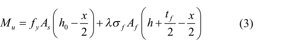
Bearing capacity calculation of TRC-reinforced beam with a secondary load
Ultimate load analysis
In some practical engineering studies of reinforcing beam structures, due to the environmental constraints, some residual load will exist on the upper part of the beam during reinforcement, which will make the beam produce certain initial stress and deflection. Compared with the original component, the reinforcement layer has certain strain lag after reinforcement, which has certain impact on the reinforcement effect. Therefore, it must be considered in the calculation in order to be more in line with the actual project. Referring to previous literature,
17
the initial strain

where
According to the literature,
18
the nominal tensile strain of textile is defined as

Then, according to the actual strain of the textile, the actual stress
where
Comparison of theoretical and experimental values
The stress lag is introduced into the calculation, and beams H1, H2, and H3 experiencing different dry–wet cycle times are used for verification, as shown in Table 6.
Comparison of sustained load beam theoretical and experimental values.
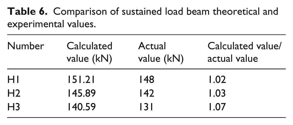
It can be seen from Table 6 that the error between the calculated value and the actual value of specimen is small, which indicates that the calculation formula can better calculate the ultimate load value of the TRC-strengthened beam with a secondary load under different dry–wet cycle numbers. As shown in Table 6, the error of beam H3 is the greatest, which may be because beam H3 is damaged as a result of sustaining load before reinforcement and the dry–wet cycle numbers are greater. These factors have great influence on the interfacial performance between TRC and old concrete, making the beam become partially debonded, and so the bearing capacity of the beam is greatly affected.
Conclusion
With the increase of dry–wet cycle numbers, the crack width and deflection of beams with a secondary load increases and the bearing capacity decreases. The overall change range is lower; therefore, TRC is suitable for reinforcing damaged beams under a chloride environment.
When the prefabricated TRC panel is reinforced to the bottom of the beam, its performance in limiting crack, bearing capacity, and deflection is close to that of cast-in-place reinforced beams in the early stage, but it is a little insufficient in the later stage.
The addition of chopped fiber has a good modification effect on TRC, which improves the crack-limiting performance of TRC and improves the reinforcement role played, which in turn improves the overall performance of the beam with a secondary load.
Based on the experimental results, the calculation formula of bearing capacity of TRC-strengthened beams with a secondary load under chloride erosion is established, and the calculated values are in good agreement with the actual values. For practical application however, much experimental verification is needed.
Footnotes
Declaration of conflicting interests
The author(s) declared no potential conflicts of interest with respect to the research, authorship, and/or publication of this article.
Funding
The author(s) disclosed receipt of the following financial support for the research, authorship, and/or publication of this article: The study was funded by the Fundamental Research Funds for the Central Universities (grant no. 2017XKZD09).