
Abstract
Short carbon fiber is an effective and essential reinforced material in composite domains. Generally, it is produced by chopping technology, among which pressing roller and grooved wheel are two popular chopping techniques. According to the working principle of these two techniques, the pressing roller can be simplified as a flexible-support cutting in off-axis transverse cutting, meanwhile the grooved wheel can be represented by a non-support cutting. To reveal the fracture difference of carbon fiber between the pressing roller and the grooved wheel technique, comparative investigation of failure behavior between a single carbon fiber (also simplified as a filament) with flexible support and with non-support was performed in off-axis transverse cutting using a custom-designed fixture. Both the cutting force and the fracture surface of the filament were comparatively analyzed in cutting process. It was found that the failure of single carbon fiber was caused by tensile effect in a non-support cutting, whereas that in a flexible-support cutting was caused by bending effect. The cutting-off force and cutting-off depth of filament cut by use flexible support are significantly lower than that by use non-support under low pre-tension. It is interesting to find out that the failure spot of carbon fiber filament in non-support cutting under low pre-tension tends to occur randomly. Meanwhile, in a flexible-support cutting, the break point of carbon fiber filament is determined by the tip of the blade. After a comprehensive comparison, the flexible-support cutting is a prior selection to produce short carbon fibers compared with the non-support cutting.
Introduction
Carbon fiber (CF) is extensively applied due to its good mechanical properties, 1 including high-specific strength and modulus, excellent electrical and thermal conductivity, strong chemical inertness, and amazing creep resistance. 2 , 3 It can be classified into continuous-CF and short-CF (also named as chopped-CF), 4 which were separated by its shape length.
The continuous-CF has hundreds of meters in its length, whereas the short-CF is only several or dozens of millimeters long. Therefore, the short-CF is regarded as a post-produced product of continuous-CF, because it is always produced by chopping continuous-CF into pieces. Compared with the continuous-CF, the short-CF possesses better processability due to its good process compatibility with traditional manufacturing processes, such as injection molding and extrusion compounding. 5 As concluded by Xie et al., 6 the short-CF accounts for nearly 13% of the total CF market, and its market share is still growing.
To date, short-CF has been widely investigated, and most of its works were focused on the properties of its post-produced composites, such as thermal properties, 7 , 8 tensile properties, 9 flexural properties, 10 conductivity property, 11 and fracture performance. 12 , 13 Only few papers discussed its manufacturing technique. Generally, the chopping process of short-CF involves feeding a cutting tool that exerts a transverse pressure upon continuous-CF. CF filaments will exhibit a totally different failure behavior compared to typical metals because of their anisotropic and abrasive properties. 14 Typically, in industrial production, the short-CF is produced from the continuous-CF using a fiber cutter and a support, 15 , 16 whose principle can be classified into two types based on the hardness of support, which are squeeze roller technology (SRT) 17 and pressing roller technology (PRT). 18 , 19 Based on the working principle, the SRT can be simplified as a rigid-support cutting and the PRT as a flexible-support cutting in off-axis transverse cutting. 20 The failure behaviors of a CF filament in both rigid-support and flexible-support cutting were investigated in previous work. 20 It was found that the flexible-support cutting was a more suitable method to decrease cutting-off force compared with the rigid-support cutting.
In addition, the chopping technology of short-CF can also refer to the production technology of chemical fibers, such as Zylon, Kevlar, Dyneema, and so on. As for chemical fibers, grooved wheel technology (GWT) is an outstanding method to produce their short fibers. It is interesting that the GWT can be simplified as a non-support cutting in off-axis transverse cutting according to its working principle, which is totally different from the flexible-support cutting of PRT. At present, lots of researchers have studied the fracture process of different chemical fibers using the non-support cutting method. Shin et al. 21 conducted cutting experiments on a Zylon yarn to investigate its fracture mechanism. They found the critical strain to initiate cutting failure of the Zylon filament depending on the pre-tension of yarn. Mayo and Wetzel 22 compared the cutting force of two single fibers with organic and inorganic structure, respectively. They used a custom-designed fixture which could adjust the cutting blade cut into a filament at different angles. Details of the failure behaviors of filaments were inferred from post-failure imaging. Hudspeth et al. 23 cut various single fibers under transverse deflection loading with three different indenters, which are a 0.30 caliber rounded head, a 0.30 caliber fragment simulation projectile, and high-carbon steel razor blades. After comparing the fiber failure strain and surfaces, they found that fibers cut via a sharp razor blade showed a drastic reduction in failure strains. Sockalingam et al. 24 summarized the development in modeling and experiments of Kevlar fibers pertinent to the deformation modes occurring during impact, which can be regarded as non-support cutting.
With regard to the successful application of non-support cutting in chemical fibers, a discussion is put forward: is it possible to use non-support cutting technique to produce short-CF rather than flexible-support cutting? To find out this answer, this work designed two simplified experiments to analyze the cutting process with different supporting constraints. One constraint is a custom-designed fixture without support, that is, non-support. The other supporting constraint is a rubber plate, that is, flexible support. 20 In both cutting processes, the ends of a tested filament are gripped. Since the pre-tension acted on a filament greatly affects the cutting process, 22 , 25 the influence of pre-tension on the fracture of a CF filament is focused on in this article.
Experiment
Simplified geometry model of chopping process
Figure 1(a) demonstrates the working principle of a traditional PRT, whose device mainly contains a rubber roller, a press roller, and a radial cutter. It should mention that the radial cutter always contains dozens of blades uniformly distributed along radial direction, such as 90 blades described in Shen et al. 15 In a PRT cutting process, first a continuous-CF tow is fed under the friction force between the press roller and the rubber roller, in which the rubber roller is the driving wheel. Then it is cut off by the rotating radial cutter, which is another slave roller of the rubber roller under a certain pressure. Finally, the as-produced chopped CFs will fall down into a container. In a single cutting procedure, as shown in Figure 1(b), the cutting process can be assumed to consist of two movements. One is a vertical main feed motion (shown in Figure 1(c)), that is, a blade pushes the CFs gradually emerging into the rubber support. Due to the bending effect, the CF tow is cut off at the tip of the blade. Another one is a tangential movement of the blade, which leads the separation movement of blade from the rubber support. 15 Therefore, an as-produced short-CF tow is cut from the pristine continuous-CF tow.

The chopping process of CF in pressing roller technology: (a) pressing roller device, (b) fiber chopping process, and (c) simplified chopping process of single CF.
Figure 2(a) illustrates the working principle of a GWT, whose equipment is mainly composed of two grooved wheels and a rotate cutter. In addition, the rotate cutter also consists of a group of blades, where the blade number is much lower than that of PRT. In a cutting process, the ends of a continuous-CF tow are also fixed, and all cutting blades conduct fiber off-axis transverse cutting. Then at one position, the tow is cut off by a blade, then the as-cut short-fiber segment will drop out gradually fed by the rotation of two grooved wheels. A chopping process in detail is shown in Figure 2(b). In this process, no support is introduced.
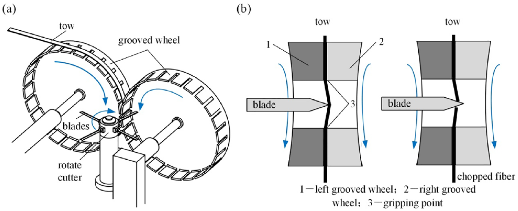
The chopping process of fiber in grooved wheel technology: (a) grooved wheel technology device and (b) fiber chopping process.
Sample preparation
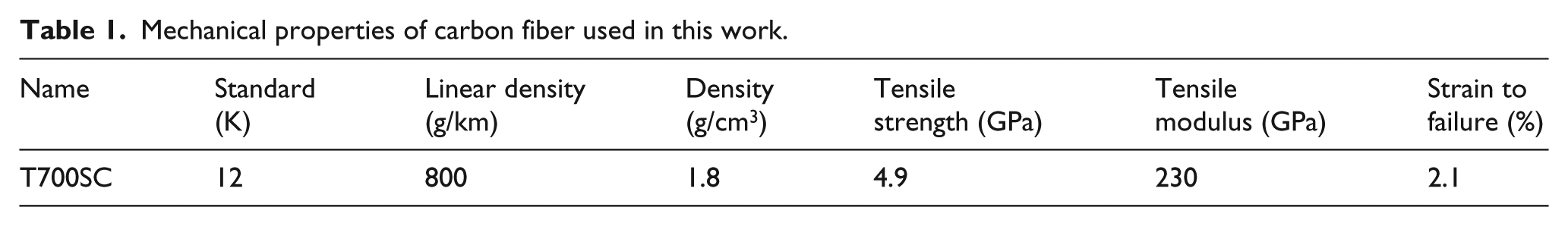
In this work, polyacrylonitrile (PAN)-based CF (T700SC, Toray, Japan) in continuous state was used as tested fiber. They were in a tow shape with 12K size (i.e. comprising 12,000 filaments) and in a diameter of 7 µm for a single filament. To get ready for subsequent filament cutting, the continuous-CF tow was trimmed into strips in the length of 70 mm. Table 1 lists some mechanical properties of the CFs used in this work.
Mechanical properties of carbon fiber used in this work.
The cutting blade was made up of commercial carbon steel (SK2, JIS G4401, Japan) with no extra surface treatment. Its dimension was 19 mm (length) × 0.9 mm (thickness) × 0.1 mm (width). Its wedge angle was 22° and its rake angle was 79°. Its surface hardness was HV 658–693. Its edge radius was 4.4 µm, which was measured via a digital optical microscope (VHX-1000, Keyence Company, Japan) at 1000× magnification. A polyurethane (PU) rubber plate (20 × 15 × 10 mm3, length × width × thickness) was used as a flexible-support constraint, and its shore hardness was 75A, which was tested according to ASTM D2240.
Experimental setup
The schematic diagram and in situ images of experimental setup are shown in Figure 3(a) and (b), respectively. A micro-displacement platform (M-VP-25XA1, Newport Corporation, USA) with an on-axis accuracy of 0.14 to 0.2 µm was used to control the feed of a cutting blade. The micro-displacement platform was connected to a tri-axial motion controller (ESP 301-3N, Newport Corporation), who itself was programmed and controlled by a personal computer. A pressure sensor (9265C1, Kistler Group, Switzerland), which was fixed onto the platform of the micro-displacement, was used to measure the cutting force of the blade during cutting a filament. This sensor was connected to a charge amplifier (5080A, Kistler Group) and then to a data acquisition system (5697A, Kistler Group), which was also connected to the aforementioned personal computer. Therefore, the load–stroke curve of cutting blade can be recorded via this computer in real time at a frequency of 100 Hz. In addition, a microscope camera (SK2700, Shenzhen Saike Technology Company, China) was used to record the macroscopically deformation of a CF filament during cutting process.

Experimental setup used in cutting CF filaments: (a) schematic diagram and (b) in situ image.
Experimental method
It is hard to exert an axial pre-tension onto a filament. 22 Because a CF filament is only 7 µm in its diameter and can only afford several micro-Newton axial load. In addition, the CF is brittle in its radial direction. Therefore, it is very fragile under a small impact. As such, it is worth noting that applying pre-tension onto a filament is an important step during a test. In this work, the pre-tension was exerted according to the testing standard ASTM D3379 and ISO 11566, as shown in Figure 4. The whole experimental process can be divided into four steps: (1) materials preparation, (2) materials assemble, (3) setting weight, and (4) applying pre-tension.

Steps of applying pre-tension upon a single CF: (a) materials preparation, (b) materials assemble, (c) setting weight, (d) applying pre-tension, (e) image of pre-tension platform, and (f) image of holding fixture.
First, a filament was separated from a CF strip which was in tow shape and consisted of 12,000 filaments and 70 mm in length. It was selected at random. Second, the as-selected filament was lightly stretched linearly and tapped its two ends onto a mounting tab, and carefully placed a small amount (or a drop) of adhesive (cyanoacrylate) on the filament at each edge of the slot and bonded the filament to the mounting tab, as shown in Figure 4(b). The mounting tab was made up of copperplate paper (250 g/m2 in areal density) and its dimension was shown in Figure 4(a). Next, one end of the mounting tab was bonded to the right fixture via a double-sided glue tape. Another side was passed through the surface of left fixture, and was put on the surface of a two-side displacement stage, as illustrated in Figure 4(c). In order to keep the CF level, double-sided glue tape is also used to fix the same copperplate paper on the left fixture. Then, a weight (value of 1, 3, 5, 7, or 10 g) was bonded to the left side of mounting tab. Finally, both sides of the mounting tab were carefully cut at four cutting points as shown in Figure 4(c). Then moved the two-axis displacement stage in the direction of Y-axis and Z-axis slowly to avoid any apparent impact acting on the weight. Once the weight left away the stage, the CF filament was stretched linearly under a pre-tension of the weight, as shown in Figure 4(e). Finally, the pre-tension was fixed by placing an adhesive drop to bond the filament at the left fixture.
After applying the pre-tension onto a tested CF filament, the off-axis transverse cutting was performed. First, the holding fixture combined with the filament was set up in the base surface of the micro-displacement. It was adjusted to have its axis of fiber in the direction of Y-axis on the micro-displacement platform. In order to create a quasi-static environment reducing the effect of fiber bouncing or wave propagation, 23 the blade was fed along the direction of Z at a relative low feeding rate, and the load–stroke curve was obtained and observed via computer. It was important to record the time that cutting blade came into contact with the single CF. The stroke, of which the load increased rapidly, was marked as the initial point (specially, that stroke point was marked as 0).
After setting the initial point, the blade returned to the position of +20 µm in the Z-axis. Then the blade was fed from +20 to −80 µm in flexible-support cutting process at a feeding rate of 1 µm/s. In non-support cutting process, the blade was fed from +200 to −2500 µm at a feeding rate of 50 µm/s. The load and stroke were recorded at intervals of 0.1 s in all cutting process. Moreover, to pick out the force generated by cutting rubber plate in a flexible-fixing cutting process, an auxiliary experiment was conducted out to determine the force produced by cutting rubber in the same condition and position. In this case, the rubber was cut without the introduction of any single CF. It should mention that each test needs to be repeated as much as possible to reduce experimental errors, due to physical properties of each CF filament selected from a tow. In this work, we have done 10 repeated experiments for each test.
In addition, the scanning electron microscope (SEM) images of failed CF were performed with a Zeiss-Merlin field emission SEM. An accelerating voltage of 5 kV was used. The working distance was between 9 and 11 mm.
Results and discussion
Force behavior
The schematic diagram of the transverse compression of a CF filament in flexible-fixing cutting is shown in Figure 5(a). The compression load F and stroke δ of cutting blade were measured. To obtain precise value, the cutting force of the CF filament should be corrected by subtracting the compression force Fr1 and Fr2, which occurs from the deformation of rubber plate. Because the diameter of a CF filament only occupies 1/10th of the blade thickness, the force Fr1 + Fr2 is simplified as Fr, which is determined by the auxiliary experiment. Thus, the cutting force of a CF filament in flexible-fixing cutting is calculated by Fc = F – Fr.

The cutting force analysis diagram of a filament chopped by a blade with different cutting techniques: (a) flexible-support cutting and (b) non-support cutting.
The schematic diagram of the transverse compression of a CF filament in non-support cutting is shown in Figure 5(b). The compression load F and stroke δ of cutting blade were measured. In this cutting process, the cutting blade only contacted with the filament. Therefore, the cutting force of the CF filament in non-support cutting is calculated by Fc = F.
Since the cutting depth and the cutting force are two important parameters in practical production, 6 the cutting force–stroke diagram is used instead of the stress–strain diagram, in which the stroke is equal to the cutting depth.
The cutting force–stroke curves of a typical flexible-support cutting and a typical non-support cutting are plotted in Figure 6(a) and (b), respectively. Similarly, their cutting force–stroke curves have two turning points in their cutting process: the instant of blade contact with CF filament (Point-M) and the breakage of the CF filament (Point-N), which is the point of peak transverse force. The cutting-off force is defined as the force at which the CF filament is broken. The cutting-off depth is defined as the stroke from Point-M to Point-N.

The cutting force–stroke curve of CF filament with different cutting techniques under 1 g pre-tension: (a) flexible-support cutting and (b) non-support cutting.
In the experiment during a cutting process, when the blade comes into contact with CF filament, which is defined as Point-M in Figure 6(a) and (b), the cutting force of CF filament begins to increase from zero. And the force continues to increase as stroke increasing. When the CF filament is severed, which is defined as Point-N in Figure 6(a) and (b), the cutting force immediately decreases to zero. The growth rate is different in these two cutting processes. The cutting force in flexible support shows a stable growth rate, which is 0.36 mN/µm. While the cutting force in the non-support cutting process shows a non-linear growth rate, which gradually accelerates as stroke increasing. The result of cutting force in non-support cutting is similar to Wang et al., 26 in which they pointed out that the initial loading was governed by bending of CF filament, and with the increase of stroke, the stretching gradually plays a dominant role.
Figure 7 illustrates the cutting-off force and cutting-off depth of CF filament cut with different pre-tensions. In the flexible-support cutting process, the cutting-off force gradually increases with increasing pre-tension, as shown in Figure 7(a); the cutting-off force with pre-tension of 1 g is 14.323 ± 1.700 mN. When the pre-tension of CF filament increases to 10 g, the cutting-off force reaches 33.020 ± 2.069 mN. In this cutting process, the cutting-off depth only varies with a small range, which is from 20 to 30 µm. In the non-support cutting process, the cutting-off force and cutting-off depth are shown in Figure 7(b). When the pre-tension of a CF filament varies at 1, 3, and 5 g, the cutting-off force keeps a relative stable level at 32 mN; subsequently, it will be followed by an apparent decrease as pre-tension further increases. For instance, when the pre-tension is 10 g, the cutting-off force (18.854 mN) decreases to the lowest in the testing range. The cutting-off depth of filaments generated in non-support cutting shows a continuous decrease trend with increasing pre-tension, that is, it decreases from 1982 µm (T0 = 1 g) to 952 µm (T0 = 10 g).

The pre-tension versus cutting-off force and cutting-off depth of CF filament cut using different cutting techniques: (a) flexible-support cutting and (b) non-support cutting.
In addition, compared with the cutting-off depth of CF filaments occurred in flexible-support and non-support cutting, they exhibit a significant different magnitude. The cutting-off depth occurred in the non-support cutting is more than 1000 µm, whereas that in a flexible-support cutting process is only 30 µm. The results indicate that the fracture processes may be different in these two cutting processes, and their fracture processes will be discussed in the following section.
Microscopy observation of fracture surface
The determination of fracture mode of CF is of great significance for studying the short cut fracture of CFs. According to the existing research, there are four main fracture modes of CF: tensile fracture, bending fracture, cutting fracture, and twisting fracture.20,27–29 And the ideal way to distinguish different modes of fracture is to observe through the fracture surface.
Figure 8 shows the SEM images of the fracture surface of CF filaments cut by different support cutting techniques. In the non-support cutting, the whole failure surface is rough, as shown in Figure 8(a). No clear crushing marks incised by blade could be observed in the fracture surface of the filament. Because the cutting load in the transverse direction is less than 35 mN, which is not enough for the blade to cut into the CF filament. This feature is similar to that reported by Tagawa and Miyata, 30 in which fiber failure was described as being caused by tension behavior. With the feeding of cutting blade, the filament would be stretched along fiber axis direction. Therefore, the tensile effect would be the dominant role in filament deformation. Once the filament reaches the elongation at break, its tensile crack is initiated and bloomed. The filament fracture process is similar to the results given by Allen. 31 The appearance of the rough failed surface provides evidence that the failure of CF filament in non-support cutting process is caused by tensile effect.

SEM images of the fracture surface of CF filament cut using different cutting techniques: (a) non-support cutting and (b) flexible-support cutting.
Figure 8(b) demonstrates the fracture surfaces of CF filaments with different pre-tensions in the case of flexible-support cutting. All fracture surfaces appear to be smooth and rough coexistence, which is similar to that appeared in the previous work, 20 in which the reported fracture surface was obtained by flexible-support cutting without pre-tension. Therefore, the failure mechanism of CF filament under pre-tension is caused by bending effect, the same as that under no pre-tension. 20 Because the transverse elastic modulus of CF is significantly higher than that of PU rubber, the CF filament is pressed into the rubber surface and bent by the cutting blade in a small area. This cutting process can be regarded as a three-point bending test, 32 in which the breakage of CF is caused by bending. The fiber is typically buckled by compression and forms kink bands at the innermost surface. With the deformation of CF, a tensile crack is initiated at the tension side which propagates transversely across the fiber. With the feeding of the blade, this crack expands inward, meeting the kink bands in the middle plane. Due to the pre-tension, the CF filament is stretched along fiber axis, and the warp of fiber become not obvious, therefore the failed surface of CF is relative flat. Interestingly, the area ratios of smooth surface and rough surface in entire surface are correlated to the value of pre-tension. With increasing pre-tension, the smooth area will take a major part, and the boundary line between smooth section and rough section is getting more obscure.
According to the microscopy observation of fracture surface, the CF filament split apart with non-support technique is due to tensile effect, and that with flexible support is attributed to bending effect.
Deformation behavior observation of CF filament in longitudinal direction
In a cutting process, the CF filament will exhibit different deformation appearance in its longitudinal direction. 33 Therefore, magnified visual methods were employed to analyze the deformation appearance of CF filaments occurred in flexible-support and non-support cutting process separately.
For the flexible-support cutting, the deformation of CF filament can be classified into three main stages, as shown in Figure 9. In Stage 1, the cutting blade gradually comes into contact with the CF filament. The critical point of this stage is the moment of starting contact, which is the Point-M in load–stroke curve. Due to the constraint of two bonding points distributed at each end, the as-cut CF filament would cling firmly to the support surface without the affection of blade. In Stage 2, the CF filament is bent toward the blade nose. With the feeding of cutting blade, the as-cut CF filament nearby the blade nose is pressed into the rubber progressively. Simultaneously, rubber surface is also indented nearby the area of blade nose. The deeper the indentation, the smaller the bending radius of CF filament, due to the constraint of flexible rubber pushing the filament toward blade nose. In addition, a high deformation energy is accumulated in the form of rubber plastic deformation that accompanies with CF bending and elongation deformation. In Stage 3, the CF filament is broken into two pieces. Once the CF filament is bent to its critical limitation, it will be failed. Subsequently, the CF filament will vibrate for a short period of time with the vibration energy from the deformation energy accumulated in Stage 1. At the end of this stage, the CF filament broken as two pieces will settle down and cling to the surface of support due to the constraint of two bonding points. It is a pity that it is very hard to capture the breaking moment of CF filament, which can be attributed to three reasons. The first reason is the extremely short period of filament broken. The second reason is the light blocking of support during observation. The third is the tiny bending radius at failed moment of CF filament, which is about 0.2 mm.

The deformation behavior of CF filament cut using flexible-fixing cutting: (a) in situ images and (b) schematic diagram.
For the non-support cutting, the deformation of CF filament in longitudinal direction can be observed with the high-speed camera at 1000 Hz, as shown in Figure 10. In the images, to make it better to observe, the outline of CF filament has been facsimiled with spline curves in a computer-aided design software (Autodesk CAD). Because the original outline of CF filament is hazy due to the tiny diameter of the filament (7 µm).

The fiber deformation behavior of CF filament observed at longitudinal direction in non-support cutting process with 1 g pre-tension, in which the breaking spot of CF filament is randomly distributed.
In a non-support cutting process, the cutting blade first comes to contact with CF filament. Then as the stroke of cutting blade increases, the angle of filament deflection begins to increase from zero, and the fiber gradually demonstrates a V-shape. When the CF filament is extended as the feed of blade, a tension would be generated along fiber axis. When the tensile strength achieves to limitation, the CF filament breaks, and the released tension along fiber axis may generate an acceleration acted on the filament. This acceleration causes the free end of the filament to shift and vibrate quickly and make the whole filament warp. Then the acceleration gradually decreases and the bending effect of the filament decreases too. The fiber has a filament deflection angle; this angle decreases and finally the filament contacts cutting blade once again.
In this work, it is interesting to find out that the failure spot of the filament exhibited random distribution along fiber axis in a certain extent. This result is similar to tensile behavior of single CF. Tanaka et al. 34 proposed that the tensile breaking point of CF depends on the position of the surface defect of the CF. However, in most cases, the breaking point at the contact spot of blade-CF filament took a major ratio in a series of tests, which may be due to the effect of stress concentration resulted from blade. To determine failure criterion, the elongation of the filament is calculated, as shown in Figure 11.

The deflection diagram of CF filament in non-support cutting process.
In a typical cutting process of non-support, the filament elongation, L, and the induced strain, ε, are given by 25


where S0 is the gauge length between grips, δ is the displacement of the cutting blade, and L0 is the initial length of CF filament with no pre-tension. In the pre-tension applied steps, the initial filament elongation, l0, can be calculated as follows
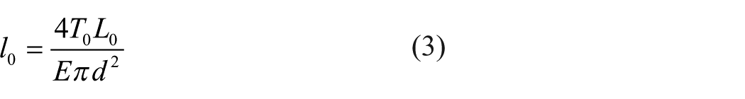
where T0 is the pre-tension of the filament, and E and d are the elasticity modulus and diameter of CF filament, respectively. The initial length of the filament, L0, can be calculated by


Therefore, combining equations (2) and (5), the elongation of CF filament affected by deflection, ε, is given by
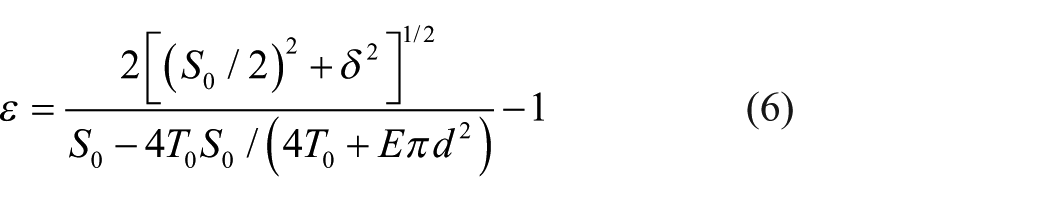
In this work, the value of S0 is 20 mm; the values of E and d are 230 Gpa and 7 µm. Combining with cutting-off depth (δ), the elongation at break of CF filament with different pre-tensions is shown in Figure 12. The break elongation with pre-tension of 1, 3, and 5 g is near 2.0%, which approaches the break elongation of CF filament in pure tension (2.1%). When the pre-tension of CF filament reaches 7 or 10 g, the break elongation decreases to 1.6%, which could be attributed to the reason that larger pre-tension leads to greater stress concentration near the cutter tip. Therefore, pre-tension in CF filament helps to reduce cut energy and may result in earlier fiber failure, which is consistent with the work of Shin et al. 25

The elongation at break of CF filament with different pre-tensions.
Conclusion
The available production technique of short-CF can be simplified into two categories, which are a flexible-support cutting and a non-support cutting. To find out their difference, the failure behavior comparative investigation of CF filaments in off-axis transverse cutting was performed under a certain pre-tension between these two techniques. The cutting-off force of CF filament generated in flexible-support technique increases with increasing pre-tension, whereas that occurred in non-support technique is just the opposite. Moreover, the cutoff depth of CF filament generated in flexible-support technique is much smaller than that in non-support technique. The fracture surfaces of CF filament acquired by flexible support appear to be smooth and rough coexistence, whereas those obtained by non-support technique exhibit only rough. The failure spot of CF filament that occurred in flexible-support technique always locates at the area nearby blade nose, while that in non-support technique randomly distributes to a certain extent. In addition, the failure of CF filament cut by flexible-support technique can be attributed to the bending effect and that by non-support can be mainly regarded as the effect of tensile failure. After a comprehensive comparison, the flexible-support technique is more suitable for short-CF production than the non-support technique.
Footnotes
Declaration of conflicting interests
The author(s) declared no potential conflicts of interest with respect to the research, authorship, and/or publication of this article.
Funding
The author(s) disclosed receipt of the following financial support for the research, authorship, and/or publication of this article: The current study was supported by the National Science Foundation of China (No. 51775197) and the Science and Technology Planning Project of Guangdong Province, China (No. 2018A050506007).