
Abstract
The study aim is to develop hybrid filament-wound polymeric composites based on flame retardant polyester resin (UPe) and multi-layer structured glass or combined carbon and glass fibers for use as ablative thermal insulation of rocket motor by wet filament winding technique. The composites have a multi-layered structure consisting of two layers of carbon (CF) or glass woven fabric (GF) and one layer of carbon or glass direct roving (CR or GR, respectively), repeated in three cycles. Structural analysis, performed using FTIR spectroscopy and dynamical-mechanical analysis, confirm highly polymerized network. Lower values of the tanδ peak height indicate improved interfacial adhesion between carbon/glass fibers and UPe. The improvements of thermal insulation index of 37% and erosion rate of 38.6% at 180°C are achieved for combined carbon/glass fiber–based composite compared to the neat UPe. Tensile and interlaminar shear properties are investigated according to the fiber orientation and the highest values of tensile and interlaminar shear strengths are obtained for composites with longitudinal orientation, 417.48 MPa and 22.30 MPa, respectively. Compared to the neat UPe, which degrades after 50 s at 3000°C, the composites are stable up to 192 s.
Introduction
Glass and carbon fiber–based composites have been designed by the wet filament winding (wFW) technique used in production of flat laminates, elbows or curved-surface, adjustable for use as construction piping systems, marine and aerospace construction elements, thermal insulators and in ballistic application.1–9 Characteristics of fiber-based composites obtained via wFW are mainly affected by their composition, geometry/shape, and process conditions, such as fiber and resin type, filler addition, winding angle, speed and tension force and finishing reinforcing layer.10,11 In general, wFW technique places the resin impregnated fibers under the defined angle and applied tension force in form of circumference of a steel tool of the desired shape.2,11 The wFW provides high production rate, quality of the products and repeatability of the composite performances compared to other fabrication techniques. 12 Moreover, this technique allows obtaining desired mechanical properties of final product with different fiber orientation. 2 In the presented work, the wFW technique is employed to produce an ablative high temperature protection material (TPM) based on flame retardant polyester resin and multi-layer structured glass or combined carbon and glass fibers which can be used as thermal insulation of the rocket motor.
Thermal insulating materials which contain an ablator are one of the most reliable TPMs used in designing construction elements for rocket motors. 13 A low-density and light-weight fiber-reinforced thermal protection composites, which exhibit excellent mechanical and energy-absorbing performances, gain increasing attention for achieving the higher requirements in the rocket aspects. 13 The most promising polymers for impregnation of carbon and glass fibers/fabrics and for production of light-weight TPM composites are phenolic, epoxy, and polyester resin.14–21 Among them, the unsaturated polyester resins (UPe) are widely used to impregnate glass and carbon fibers or fabrics due to good compatibility, high protection potential related to the corrosion, extreme temperature and internal pressure. 2 UPe-based composites, reinforced with glass/carbon fibers, represent typical engineering construction materials of high standards with regards to mechanical and thermal properties.15,22 Moreover, such composites possess an appropriate temperature range according to the application conditions (thermal insulation of rocket motor or nozzle, inhibition of solid rocket propellant grain, etc.)2,23 and steel retain low weight to thickness ratio due to low density. 13 There are various methods of production of polymer-based carbon/glass fiber composites, such as hand lay-up method, 14 vacuum infusion and microwave-assisted compression molding 24 but wFW provides potential to adjust certain properties, so it is commonly used for the designing of rocket motors.2,25
Properties of wFW obtained composites depend on the filament structure and applied reinforcing agent as well. 26 There are several phenomena associated with glass fiber melting and reacting with the charring UPe polymer matrix, which are followed with formatting of mechanically stable silicon carbide structure and heat adsorption during the phase transformation. 16 In contrast, carbon fibers are good heat conductors and possess high specific strength and modulus. Thermal properties of such structures can be improved by introducing powdered fillers such as micro- or nano-silicon dioxide,27,28 alumina tri-hydrate,29–31 and graphene-nanoplatelets 14 in a polymer matrix prior to fiber impregnation. 16 These fillers exhibit a synergistic effect with the fibers in terms of improving thermal characteristics as demonstrated in the following literature. 14 Hence, alumina tri-hydrate as low-cost, thermally stable upon 800°C with a total weight loss of 7.4% 32 can be effectively used to increase the heat resistance of fiber-reinforced polymer composites. 29 The effect of alumina tri-hydrate on fire resistance of polymers can be summarized by the following effects: cooling down the polymer burning surface (heat sink material); releasing water vapor during the thermal decomposition causing the dilution of the combustible gases; forming insulating protective barrier of aluminum (III) oxide; and reducing smoke emission. 33
The aim of this study was to develop multi-layer structured composites where matrix was self-extinguished halogen-free UPe resin containing alumina tri-hydrate, while reinforcements were carbon or glass woven roving in first layer and carbon or glass direct roving in following layers. The carbon/glass multi-layered composite structures were manufactured by the wFW technique and the effects of interlayers on mechanical, rheological and thermal properties of the resulting composites were examined. These tests took into consideration the following aspects: (a) development of standard glass fiber-based composite; (b) development of hybrid carbon/glass fiber-based composite; (c) effect of fiber orientation on mechanical properties; (d) effect of force load transmission (through carbon or glass layer) on interlaminar shear properties; and (e) effect of material composition on thermal and mechanical characteristics. The materials developed in this study could be used as fire-resistant ablative thermal insulation of rocket motor.
Experimental
Materials
Carbon fiber GG206P (G. Angeloni. S.r.l., Italy, characteristics: 200 g/m2, plane, width 30 mm, and thickness 0.19 mm) and medium-heavy fiberglass woven roving (R&D Faserverbundwerkstoffe, GmbH, Germany, characteristics: 200 g/m2, plane, width 30 mm, and thickness 0.22 mm); carbon fiber Tenax HTS40 F13, 800 tex (R&D Faserverbundwerkstoffe GmbH, Germany) and fiberglass direct roving, 300 tex (Kelteks Ltd, Croatia), were used for the production of the flat composite laminates. Pre-filled, unsaturated halogen-free UPe resin, Dion® FR 7721-00, (Reichhold, USA), which contained alumina tri-hydrate as fire-retardant was used as polymer matrix for composite preparation. The 50% solution of the methyl ethyl ketone peroxide in toluene (MEKP, Sigma Aldrich, Germany) was used as UPe resin initiator/hardener.
Samples Preparation
Composite laminates were prepared using wFW machine (Forplex Plasterex, France), equipped with GE Fanuc series O-T software (Figure 1 Forplex plasterex filament winding machine.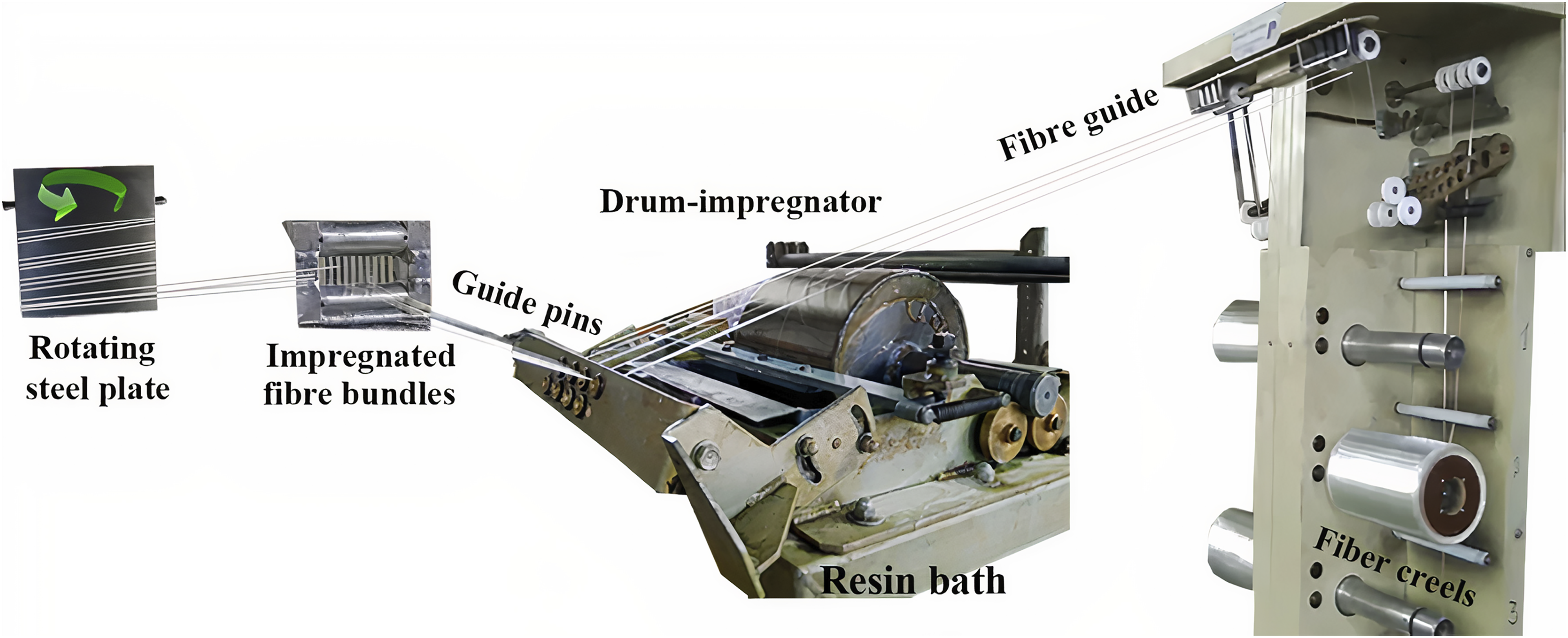
The cured carbon/glass multi-layered composite samples were designated as UPe_GF (only glass-based reinforcement) and UPe_CGF (combined glass- and carbon-based reinforcement) and shown in Figure 2. Structure of the a) GG206P carbon and b) R&D Faserverbundwerkstoffe glass fabric; and of the cured c) UPe_CGF and d) UPe_GF multi-layered composite structure.
Characterization Methods
The density of cured carbon/glass multi-layered composite samples was determined according to the ISO 1183-1:2012 standard, Plastics—Methods for determining the density of noncellular plastics. 34
Fourier transforms infrared spectroscopy (FTIR) spectra of the cured composite were recorded in absorbance mode using a Nicolet™ iS™ 10 FTIR Spectrometer (Thermo Fisher Scientific, USA) with Smart iTR™ FTIR sampling accessories, within a range of 400–4000 cm–1, at a resolution of 4 cm−1 and in 20 scan mode.
Dynamic-mechanical analysis (DMA) study of the cured composite samples was performed in torsion deformation mode using the Modular Compact Rheometer MCR-302 (Anton Paar GmbH, Austria) equipped with standard fixtures (SRF12) for rectangular bars, temperature chamber (CTD-620) having high temperature stability (±0.1). The standard sample of a rectangular bar shape (44 × 10 × 4 mm) was tested by using “temperature ramp test”' at temperature range from 40°C to 180°C, the heating rate was 5°C·min−1, the single angular frequency of 1 Hz, and strain amplitude was 0.01%.
Thermal properties of the cured DION® FR 7721-00 resin and composite inhibitor were studied by a modified oxyacetylene ablation testing of thermal insulation materials
35
using an high-temperature infrared thermometer (Extech, Boston, Massachusett, USA) and an oxyacetylene flame (Supplementary Figure 1(a) in Online Supplement Material). Samples of standard dimension (100 × 100 × 6 mm) were used. The following parameters were obtained as test results: insulation index (IT), erosion rate (E), temperature (Tb) and time (tb) of combustion. Schematic diagram for the a) tensile and b) interlaminar shear strength testing.
Bond strength between composites and aluminized composite rocket propellant was determined using standard adhesion tests by Instron 1122 Universal Testing Instrument (Instron, Norwood, Massachusett, USA), at 20°C with force loading rate of 10 mm·min−1 (Supplementary Figure 1 in Online Supplement Material).
Interlaminar shear strength was determined using standard ASTM D2344 test, 36 while uniaxial tensile test was determined using standard ASTM D3039 37 using Schenck Trebel RM 100 (RoTec GmbH, Darmstadt, Germany). Two load directions were applied during the interlaminar shear strength evaluation: over carbon and glass layer for UPe_CGF composite. Longitudinal and transverse tensile strengths were determined for both composite laminates. Schematic diagrams for the tensile and interlaminar shear strength tests are shown in Figure 3.
Failure analysis of the cured composites and samples after mechanical characterization was performed using SMTV Visor Inspection System (Michael Bruch, Germany).
Results and Discussion
Density of Composite Material
Experimental conditions and density determination results.

FTIR Analysis
FTIR spectra of uncured neat DION® FR 7721-00 resin, cured UPe_CGF composite and CF and GF are presented in Figure 4. The peaks observed in the FTIR spectra of UPe and UPe_CGF around values of 3618, 3524, 3444, and 3375 cm−1 and the low intensity peak at 697 cm−1 originate from hydroxyl (OH) groups stretching vibrations of resin and alumina tri-hydrate, which is used as a flame retardant in the polymer matrix. The alumina tri-hydrate filler exhibits peaks at lower wavenumber (around 500 and 1150 cm−1) corresponding to Al-O bonds,
39
but these peaks are overlapping with the ones originating from the valence vibration of polyester backbone. FTIR spectrum of the cured composite UPe_CGF, uncured UPe, carbon fabric (CF) and glass fabric (GF).
Symmetric and asymmetric vibrations of methyl (CH3) and methylene (CH2) groups are observed around values of 3050, 2825, and 2840 cm−1, while their bending vibrations are remarked at about 1454 cm−1. 15,40 The intensity of these peaks is significantly reduced in FTIR spectrum of cured UPe_CGF composite. The band at 1728 cm−1 in the FTIR spectrum of the corresponding composite originates from carbonyl C=O (ester) group present in the polyester resin. 15 This peak is shifted to a higher wavenumber compared to the neat UPe (1720 cm−1) indicating interactions between resin and CF, CR and glass fibers. Moreover, ester C-O stretching vibration is observed at about 1372 cm−1. 15 The peak at 1490 cm−1 in UPe originates from the stretching vibration of the C=C and disappears after curing. Si-O-Si vibrations are observed as a broad peak at 915 cm−1. Similar FTIR results are obtained for the UPe_GF sample.
Dynamic-Mechanical Analysis
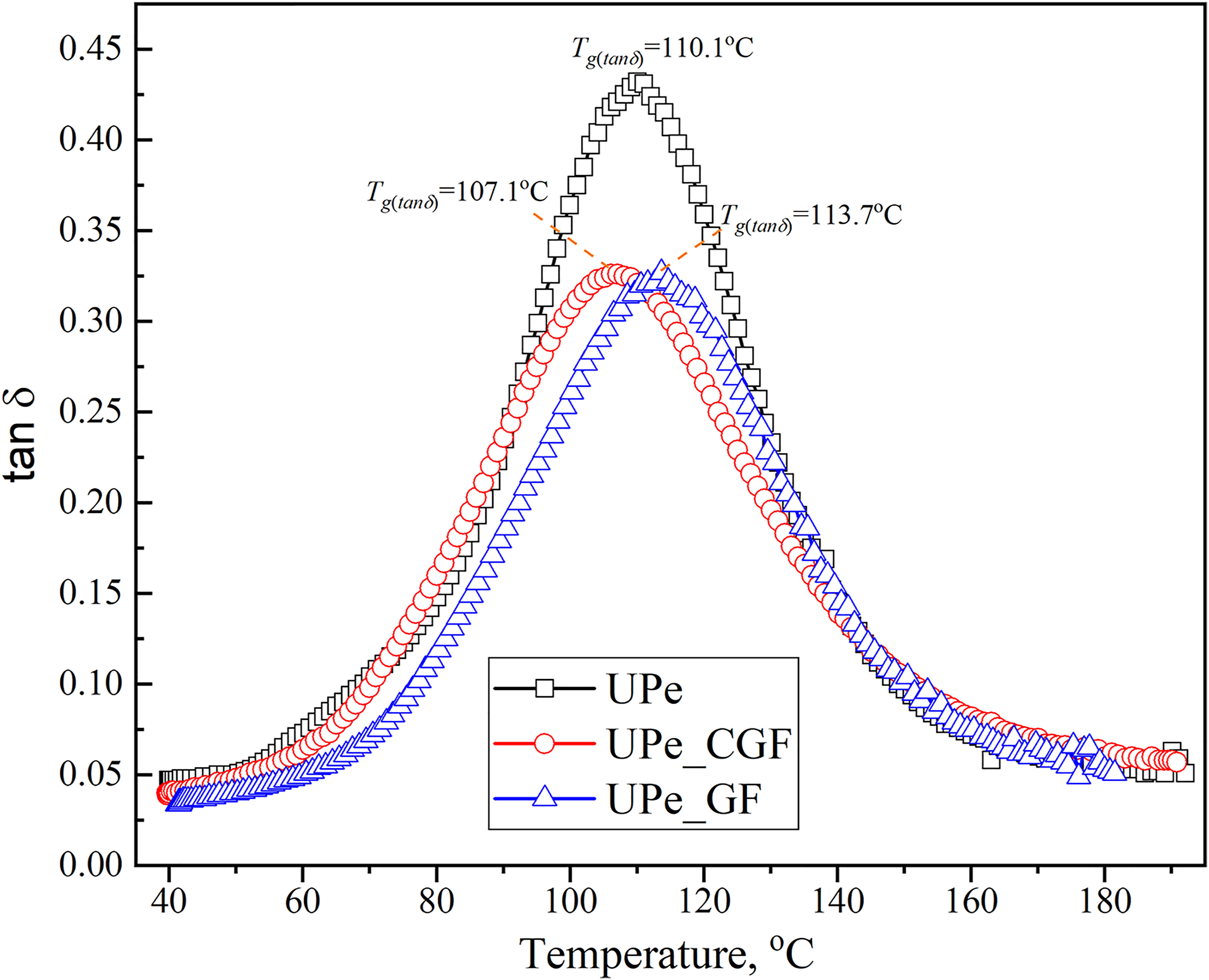
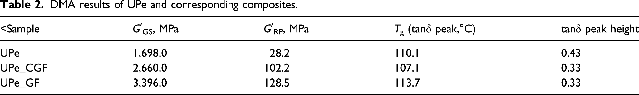
DMA is a standard technique used to investigate viscoelastic properties of polymers in a wide temperature range. The temperature dependences of storage modulus (G′), loss modulus (G″) and damping factor (tanδ) of cured UPe resin, UPe_GF and UPe_CGF composites are shown in Figures 5 and 6. G′ reflects elastic, while G″ reflects viscous behavior of polymer matrix. In addition, Table 2 shows rheological characteristics of analyzed samples: storage modulus in glassy state and rubbery plateau (G′GS and G′RP, respectively), glass transition temperature (Tg) and tanδ peak height. Temperature dependence of storage modulus (G′) and loss modulus (G″) of cured UPe resin and corresponding composites. Temperature dependence of tanδ of cured UPe resin and corresponding composites. DMA results of UPe and corresponding composites.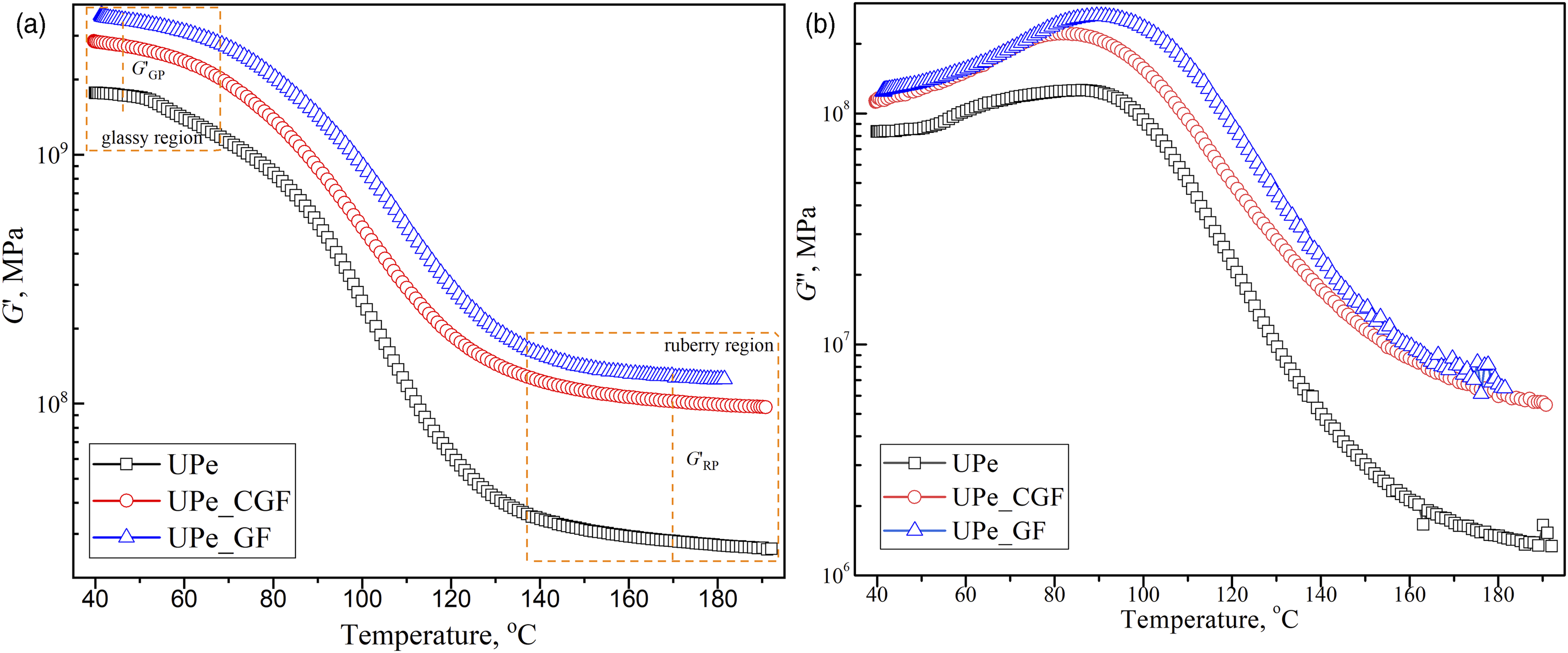
It can be noticed that composites display higher values of the G′ in glassy state compared to the neat UPe resin. Such a phenomenon is associated to the strength of fiber/matrix interactions and the way the polymer chains are packaged. 41 An increase in temperature causes a decrease in G′ for all samples which is the consequence of greater movement of the polymer segments. Composites display a smaller drop in G′ as temperature increases, which is manifested in one relaxation process, implying that reinforced resin possesses homogeneity in structure, that is, wetting of fibers is quite satisfied. In general, composites exhibit a significantly higher G′ in a rubbery plateau than neat resin, whereby the one containing only GF shows a slightly greater value compared to one with the combined carbon and glass fibers. Although carbon fibers possesses a higher rigidity than GF and therefore less mobility under the influence of increased temperature, there is probably poor CF wetting with UPe resin which results in a lower G′ for corresponding composite compared to the material containing only glass fibers.
Obtained increase of G′ values for composites samples indicates that carbon and/or glass fibers increase the UPe capacity to support mechanical constraints with recoverable deformation, while composites stiffness is substantially increased. 42
Figure 5(b) shows that G″ slightly rises to the transition region and then significantly decreases as the temperature continues to increase for all samples. That increase in value of loss modulus in the transition region is attributed to internal friction which promotes energy dissipation caused by the presence of reinforcements.43,44 Internal friction is the result of polymer bridges sliding along other parts of the molecular network and carbon or glass fibers. In addition, such an increase in G″ also occurs due to the movement of free domains of the UPe segment present between linked network. 45 The slight broadening of the G″ peak for composites compared to UPe resin indicates the effect of fibers incorporation, which inhibits the relaxation process in reinforced materials. 46 A significant drop in G″ for all samples is a result of favorable free motion of the macromolecule segments within the polymer structure.
The tanδ height values are similar for UPe_CGF and UPe_GF composites; however, the tanδ height value for cured UPe at the Tg is ≈30% higher than for composites. Decrease in tanδ height values for composite is usually caused by the restriction of the free movement of the polyester resin chain segments. 44 Also, lowering of tanδ peak value for composites indicates good interfacial adhesion between carbon/glass fibers and UPe matrix.
The glass transition temperature (Tg) is determined from tanδ peak position (Figure 6) and it reaches a value of 110.1°C for neat UPe resin, 107.1 and 113.7°C for UPe_CGF and UPe_GF composites, respectively. The increase in Tg for UPe_GF occurs due to the immobilization of the UPe macromolecular chains near the surface of the glass fibers. 47 The slightly decrease in Tg for hybrid UPe_CGF composite occurs due to higher rigidity of the woven carbon fibers, which causes lowering the temperature of relaxation. 42 Similar results are obtained in DMA studies done on pine apple/glass hybrid composites, natural/glass fibers composites and carbon/glass hybrid composites. 42
Thermal Properties
Physical characteristics (mass before (m1) and after (m2) ablation test, and mass loss (Δm)) of the sample before and after flammability test.

atb represents the time of degradation.
bTb represents the temperature of degradation.
c oxyacetylene flame temperature ≈3000°C.

Sample of cured UPe and UPe_GF and UPe_CGF composites before (a) to (c) and after ablation test (d) to (i).
Values of isolation indexes at 80 and 180°C and erosion rate.

Table 3 shows that time to ignition for the neat UPe resin is 50 s, while the composites have significantly greater thermal stability, 242% and 264% higher than the resin. When the polymeric material is exposed to a hyperthermal environment, temperature at the surface starts increasing and thermally induced reactions take place, resulting in the formation of gaseous products and charred residue. 16 However, this char does not have enough mechanical integrity, cracks easily and allows the transfer of heat flux to the virgin material, causing its further degradation. The introduction of reinforcements within the polymer structure, such as CF, CR, or glass fibers, is beneficial in several ways: fibers endothermically absorb heat and give mechanical strength to the charred/carbonaceous material. 16 This is particularly significant for combustion of thermally inhibited propellant, when mechanically weak protection layer (char) can be mechanically eroded/removed by the friction action exercised by the high pressure and combustion products.16,48 The highest insulation capacity is achieved for UPe_CGF at both investigated temperatures. Erosion rate decreases significantly for UPe_CGF and UPe_GF composites compared to the neat UPe resin (Table 4). The introduction of fibers reduces delamination between these polymer phases (Figure 7).16,48 Moreover, glass and carbon fibers in composite undergo many endothermic processes, such as melting and evaporation, thus working as an additional heat sink.16,48 From the point of view of rocket motor design, both composites meet requirements of thermal stability.
Mechanical Properties
Maximal shear force (Fmax) and interlaminar shear strength (τ) for UPe_GF and UPe_CGF composites.

aForce load through carbon layer.
bForce load through glass layer.
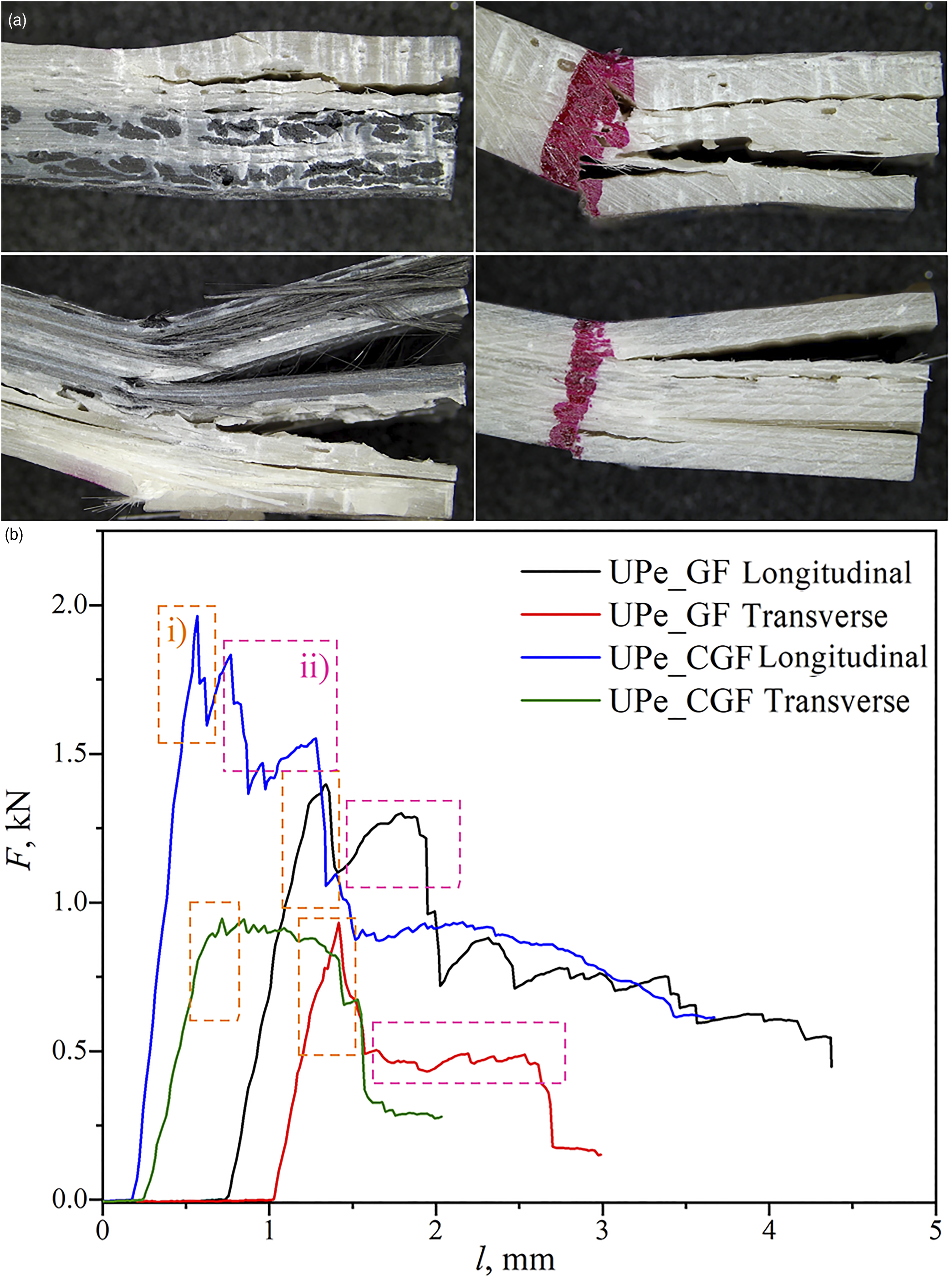
(a) Samples subjected to interlaminar shear strength test; (b) load–displacement curves.
Based on the mean results of six specimens, it is demonstrated that the longitudinal fiber orientation shows dominated impact to the tensile strength and maximal forces of UPe/GF and UPe/CGF composites. 49 It is clearly remarked that longitudinal tensile strength is more than five times higher than transverse tensile strength for UPe/GF and more than 10 times higher for the UPe/CGF, suggesting the high anisotropy of analyzed composites. However, the lowest value for transverse tensile strength shows UPe/CGF composite. Moreover, the decreasing in transverse tensile strength also lies in smaller or bigger disruption within the material structure that occurs during mechanical processing of samples (cutting the standard specimens) from unidirectional flat sheets. 26 It is demonstrated that cutting laminates containing fibers transversely in the carbon and glass fiber direction can cause damages within the laminate structure and reduce the mechanical properties as well. 26
Furthermore, uniformity of the mean values of longitudinal tensile strength (Xt) for both UPe/GF and UPe/CGF laminates is observed.
26
Standard deviation of Xt was 4.5% and 8.1% for UPe/CGF and UPe/GF, respectively. Lower uniformity of the transverse tensile strength (Yt) values, up to 13.4% for UPe_GF, is obtained (Table 6). Corresponding load-displacement curves are shown in Figure 9. Composites exhibit elastic failure, which is reflected by the linear growth of force with displacement up to maximum determined values. After that, the intra- and interlaminar failures of the composites are remarked (Figure 9), which are followed by fall and re-growth of force values (serrated force-elongation plot). Samples subjected to the longitudinal tensile tests show delamination of the CF and GF. Opposite is observed for the composites subjected to the transverse tensile test. Schematic diagram of comparation of the tensile and interlaminar shear strength is shown in Supplementary Figure 3 in the Online Supplemental Material. (a) Load–displacement curves; (b) samples subjected to tensile tests. Maximum tensile force (Fmax) and longitudinal and transverse tensile strength (Xt and Yt) for UPe_GF and UPe_CGF composites.

Bond Strength between Composites and Aluminized Composite Rocket Propellant
The dependence of the length of peel on the force load is obtained a result of the adhesion test (Figure 10). It can be remarked that the force increases linearly up to 2.5 N, after which the composite rocket propellant breaks. The bonding strength between UPe_GF and composite propellant shows a slightly lower value of the force plateau, around 1.57 N, after which a rupture occurs. This indicates a slightly weaker adhesion of propellant and UPe_GF material. The smoothness of the F-l curve indicates that a uniform bond is achieved between UPe_CGF and composite rocket propellant over the entire contact surface. This phenomenon is associated with adequate sample preparation and good adhesion between these two materials. In addition, the break of the propellant implies that the adhesion forces are greater than cohesion forces within the propellant structures. High adhesion is a prerequisite for the application of composite materials such as TPM in rocket propellant grains design. De-bonding between composite and propellant is undesirable due to increasing the burning surface, which causes spreading flames, reducing efficiency and finally motor failure. This indicates a slightly weaker adhesion of propellant and UPe_GF material reinforced with only glass fibers. Curve of dependence of load force and length of peel.
Conclusion
The presented paper confirmed the usability potential of ablative multi-layered polymeric composites, based on self-extinguished UPe and carbon/glass fibers, as TPM in rocket propellant grain design. Composites prepared by the wFW using plane carbon or fiberglass woven roving, 200 g/m2, carbon and fiberglass direct roving and halogen-free unsaturated polyester resin showed good dimensional, mechanical and thermal stability. Thermal properties of the prepared composite inhibitors were studied by ablation test, while mechanical properties were determined using dynamic-mechanical, tensile and interlaminar shear strength analysis. Improved mechanical properties, e.g. higher values of tensile and interlaminar shear strength are obtained for hybrid carbon/glass fiber-based composite compared to the neat UPe and UPe_GF as well. Accordingly, longitudinal fiber orientation in hybrid UPe_CGF sample provides the highest shear and tensile strengths of 22.30 MPa and 417.48 MPa, respectively. Moreover, hybrid UPe_CGF shows excellent thermal stability up to 192 s at 3000°C and significant improvements of isolation index at 180°C for 37% and erosion rate for 38.6%. Ablation and mechanical tests indicated that hybrid UPe_CGF composite could be applied as TPM in designing of rocket motors.
Supplemental Material
sj-pdf-1-ppc-10.1177_09673911211056787 – Supplemental Material for Using potential of filament-wound carbon/glass polymeric composites as rocket motor thermal insulation
Supplemental Material, sj-pdf-1-ppc-10.1177_09673911211056787 for Using potential of filament-wound carbon/glass polymeric composites as rocket motor thermal insulation by Jelena Rusmirović, Jela Galović, Marija Kluz, Srdja Perković, Saša Brzić, Marica Bogosavljević, Aleksandar Milojković and Tihomir Kovačević in Polymers and Polymer Composites
Footnotes
Acknowledgments
The authors are grateful to the Ministry of Education, Science and Technological Development of the Republic of Serbia for the support provided, as part of the project: Contract No. 451-03-9/2021-14/200325.
Declaration of conflicting interests
The author(s) declared no potential conflicts of interest with respect to the research, authorship, and/or publication of this article.
Funding
The author(s) received no financial support for the research, authorship, and/or publication of this article.
Data availability statement
The datasets generated during and/or analyzed during the current study are available from the corresponding author on reasonable request.
Supplemental material
Supplemental material for this article is available online.