
Abstract
Comparative analysis has been performed on the mechanical properties of hollow and solid polyester monofilament with identical external diameter. Tensile test of hollow polyester monofilament was conducted to study the influence of hollow core and the manufacturing method on the tensile fracture mechanism of hollow monofilament. The compressive properties of hollow monofilament were determined to provide a bundle-compression method to study the behavior of hollow polyester monofilament under axial compressive loading and compare with solid one. The results show that the tensile property of the hollow monofilament has smaller breaking force and higher breaking elongation than solid monofilament in case of identical external diameter. Under compression loading, the solid monofilament show better compressive properties than hollow one with identical diameter. The hollow core only affects the values of compressive strain and stress, but it has no effect on the compression and deformation mechanism. The study results also show that the polyester monofilament can show better mechanical properties than the solid polyester monofilament for the same weight. This study can help to design the lighter textile materials with the hollow polyester monofilament.
Keywords
Hollow structures are materials with a defined boundary and an interior cavity. They have low density, high pore volume, light mass, and charge-transport length.1,2 Hollow fiber is such fiber with hollow structure, including simple hollow fiber and intricate hollow fiber. Simple hollow fiber, known as hollow monofilament, possesses a single shell encapsulating a cavity at the center. And intricate hollow fiber is composed of dozens of hollow filament with circular cross-sections.
The earliest used and frequently used hollow fibers are hollow glass fiber (HGF). They can be successfully manufactured with various diameters and varying degrees of hollowness, showing great potential in enhancing the performance of composites under bending and compressive loads. Since 1963, some researchers have used HGF reinforced materials to achieve lighter mass and less performance loss.3,4 Boniface et al. 5 performed a comparative study on impact behavior of solid and hollow S2 fiber laminates. The result showed that hollow fiber laminates had less damaged area and better energy absorption properties compared with solid ones. Rosen and Ketler 4 studied hollow and solid glass fiber, and their application in composites. Hollow glass fiber gave higher stiffness and compressive strength than solid one. Hucker et al.6–8 studied the experimental evaluation of unidirectional hollow glass fiber/epoxy composites under compressive loading and investigated into the behavior of hollow glass fiber bundles under compressive loading to further show the advantages of HGF in enhancing the performance of composites. The results show the hollow fibers possess higher bending stiffness, comparing with solid fibers of the same linear density. Hollowness K2 was defined as the ratio of the internal (d) and the external (D) diameter of the fiber, as in equation (1)

Specific compression strength increases 10% with K2 = 0.22 compared with equivalent solid fibers.
Bayat and Aghdam 9 found that hollow fiber had less detrimental residual stress in the fiber due to fast cooling. And the finite element (FE) analysis indicated that the increasing hollow fraction would give high energy absorbing capacity of the composites. In particular, the high specific surface area of hollow fibers gives them potential in storing healing and damage indicating fluid, as an alternative to microcapsules. A study on the improvement of impact damage resistance of epoxy-matrix composites using ductile hollow fibers was conducted by Nasr-Isfahani et al. 10 It was observed that hollow ductile fibers gave lower weight and better impact damage. The elastic modulus of hollow monofilament is higher than solid one, indicating hollow monofilament gives higher stiffness. Hucker et al. 11 also investigated the effect of manufacturing parameters on fiber strength. Solid fibers display familiar pattern of lower tensile strength with increasing fiber diameters. Higher draw speed and lower temperature appear to give higher tensile strength. While for hollow fibers, it shows that higher draw tension, higher viscosity, and lower draw rate result in higher fiber strength. Kling and Czigany 12 performed a comparative analysis of hollow and solid fibers. The breaking force of hollow fiber is smaller than solid ones, but the tensile strength is higher by 95%. The possible reason is that fewer defects in the cross-section of hollow fibers for smaller wall thickness and higher orientation of the molecular. The fiber tensile strength increases with the decreasing fiber cross-sectional filling factor (FCF). FCF indicates the cross-sectional area surface ratio of the hollow fiber. Hollow fibers have 33% smaller deflection and 45% higher flexural modulus than solid ones when the holes of hollow fiber in positive position.
Previous studies focus on the mechanical properties of hollow glass fiber; however, the brittleness of hollow glass fiber limits its application. Now, the hollow polyester monofilament has been employed in the textile industrial; however, there has no such study on the mechanical behaviors of hollow polyester monofilament. The current research focus on the compressive behavior and tensile behaviors of hollow polyester monofilament with better flexibility and greater strength. For this study, solid polyester monofilaments with a diameter of 0.2 mm, hollow polyester monofilaments with an external diameter of 0.2 mm, and a hollowness of 25% were selected as materials to ascertain the effect of hollow fraction on mechanical properties of hollow polyester monofilament.
Materials and test method
Monofilament
The monofilament types selected are detailed in Table 1. All the applied monofilaments were purchased from Nantong Newtec Textile & Chemical Fiber Co. Ltd.
Polyester monofilament types used for the investigation.

Scanning electron microscopic (SEM) images of polyester monofilament are given in Figure 1. Figure 1(a) shows that the hollow fraction is continuous, consistent, and concentric. Figure 1(b) and (d) shows longitudinal surface. There is an obvious straight line on longitudinal section of hollow monofilament. In fact, another two lines are hidden. The reason is that the cross-sectional shape of the nozzle hole in the spinneret has three slits.
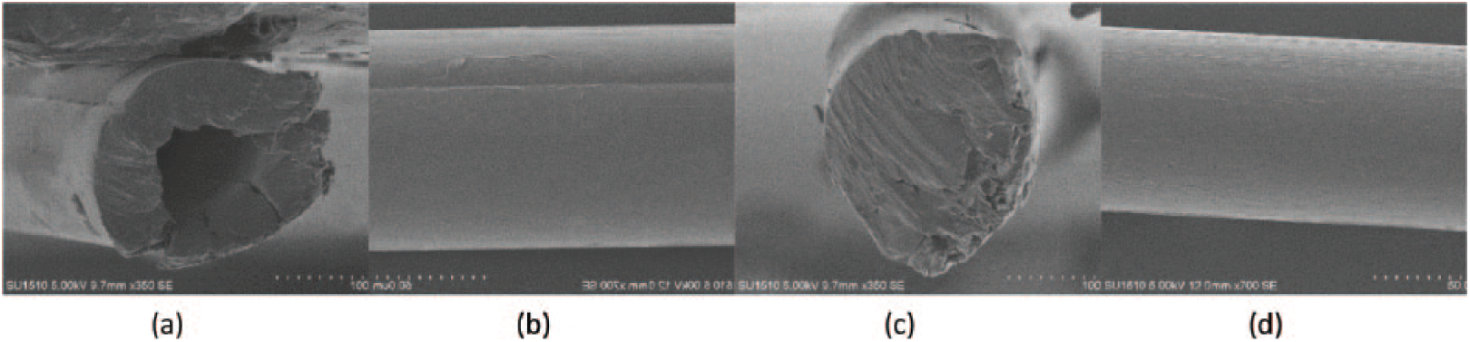
SEM images of polyester monofilament. (a) Cross section of hollow monofilament, (b) longitudinal surface of hollow monofilament, (c) cross section of solid monofilament, and (d) longitudinal surface of solid monofilament.
Determination of the monofilament tensile properties
The tensile test was performed on a SHIMADZU AGS-X universal electromechanical tester with 250 mm clamping length and a speed of 2 mm/min. Supposing a continuous, consistent, and concentric holes in hollow monofilaments, the cross-sectional area of both kinds of monofilaments can be calculated. The breaking force and tensile strength can be read, and breaking rate can be calculated according to the breaking elongation. And Young’s modulus is calculated from the load–displacement curve.
Determination of the monofilament compression property
Single monofilament gives smaller cross area and lager length–width ratio. It cannot keep upright along axial direction and the compressive load is outrange and uneven. Monofilament bundles and horizontal supporter appear to be used. Two silicone rubber blocks of approximately 20 × 20 × 5 mm provide enough support for compression. The bundles are fixed on the center and drilled through the blocks to keep upright, as shown in Figure 2(a). Silicone rubber is soft and there is no stress concentration at the joint between silicone rubber and monofilament bundles. Stress concentration will cause premature failure.

(a) Bundles fixed by silicone rubber blocks and (b) overview of packing assumed in an ideal monofilament bundle.
While the numbers of the bundles were 10, it was calculated to give an approximately circular cross-section for calculation of the area of monofilament bundle. Figure 2(b) shows an overview of packing assumed in an ideal monofilament bundle. The primary objective of this investigation was to study the effect of hollow fraction on compression resistance of polyester monofilament, not the compressive strength. The bending must occur before damage. Therefore, the compressive gauge length had to be long enough to bend and keep uniform stress distribution along the bundles. It also means the compressive strength of the bundle should be more than the critical strength at which buckling occurs.
The bundle is assumed as slender columns. For slender columns under axial loading, if the length of the bundle (L (mm)), compression elastic modulus (E (MPa)), section moment of inertia (I (mm4)), cross-sectional area (A (mm4)), and length factor (μ) are known, then critical pressure (Fcr (N)) and critical stress (σcr (MPa)) at which the buckling occurs could be defined. Supposing that the cross-section of the bundle is the ideal circular cross-section with a diameter of 0.8 mm, then section moment of inertia (I (mm4)) and cross-sectional area (A (mm4)) can be calculated. And the specimen is a slender columns fixed at both ends, so length factor (μ) is 0.5


Tensile elastic modulus and tensile strength of single monofilament can be calculated from the tensile test. Supposing that the compression elastic modulus is equal to tensile elastic modulus, compression strength is equal to 60% of tensile strength, and compression elastic modulus and compression strength of bundles are 10 times of single monofilament. Compression strength is critical stress. Actually, compression elastic modulus and compression strength of bundles may be greater than single monofilament for interaction between monofilaments. The result shows that L should be greater than 5.6 mm. Therefore, 10 mm is selected as the compressive gauge length.
FZ/T01051.1-1998 (Textile materials and textile products: Compression property – part I: determination of lasting compression characteristics) is chosen as the standard. YuanFeng YF-900 Universal material machine was employed to perform the compression tests. A 200-N load cell was used. The specimens were put between the pressure plates. The upper plate drops by 8 mm and goes back, repeating 20 times. The loading is 5 mm/min with displacement and load recorded.
Results and discussion
Monofilament tensile test
The load–displacement curve of the monofilaments is shown in Figure 3. The hollow monofilament and the solid tensile curve have the same tendency. During the stretching process, the breaking strength of the solid monofilament is greater than that of the hollow monofilament, and the elongation at break is smaller than that of the hollow monofilament. The tensile curve consists of two parts. The first part of the monofilament is in the elastic stretching stage. Due to the good compressive resilience of the polyester monofilament, the monofilament can return to the initial state after the external force is removed; the second part of the monofilament is in the stage of plastic tensile deformation. The monofilament is plastically deformed and is still deformed after the external force is removed. Although the fracture of the hollow monofilament is a three-part sequential fracture, the occurrence of the fracture is rapid and there is no significant fluctuation in the curve. As there is an initial tension, the load is not zero at the beginning of the test.

Load–displacement curve of the monofilament.
The tensile fracture properties of the monofilament are related to the internal structure of the monofilament. The fracture occurs in the structural weakness point along the longitudinal direction of the monofilament and extends to the periphery until the monofilament is completely broken. The spinneret used in the monofilament involved in this experiment is a tri-arc nozzle hole, including three slits, so the hollow monofilament is composed of three parts; the solid monofilament is a complete structure. Due to the particularity of the nozzle holes used in the production of hollow monofilaments, there is a significant difference in the stretching process between the hollow monofilament and the solid monofilament. Figure 4(a) and (b) shows the nozzle holes of monofilaments in the spinneret.

Monofilaments. (a) The nozzle holes of hollow monofilament, (b) the nozzle holes of solid monofilament, (c) the broken hollow monofilament, and (d) the broken solid monofilament.
The tensile fracture process of hollow monofilaments consists of three stages.
Stage 1. The weakest part of the three parts of the hollow monofilament begins to break.
Stage 2. The weaker part of the other two parts of the hollow monofilament breaks.
Stage 3. The last remaining part of the hollow monofilament breaks and the hollow monofilament is completely broken.
The tensile fracture process of a solid monofilament is such that the weakest point in the length direction begins to break and spreads to the entire cross-section direction, and the monofilament is completely broken.
As is shown in Figure 4(c), the broken monofilament was divided into three parts. While the nozzle hole of solid monofilament is a whole circle, the monofilament is an integral part. The breaking of solid monofilament is the breaking of the whole part. There is only an integral part, which is shown in Figure 4(d).
According to the tensile load–displacement curve of the monofilament, the tensile results of the monofilament can be calculated as shown in Table 2. The breaking strength of solid monofilament is 47.9% larger than that of hollow monofilament. The breaking strength of hollow monofilament is actually the breaking strength of the final fracture part of the three parts of monofilament, and its area is less than one-third of the cross-sectional area of solid monofilament. The solid monofilament elongation is 21% smaller than that of the hollow monofilament, indicating that the tensile deformation ability of the hollow monofilament is better. The fracture stress is the maximum tensile force of the fiber per unit area. The fracture stress of the solid monofilament is 36% of the hollow monofilament. The reason is that the thin-walled structure of the hollow monofilament reduces the defects on the cross-sectional area of the monofilament and improves the degree of orientation of the molecular chain. The elastic modulus was calculated from the gradient of the tensile curve on the 0.05% and 0.25% relative strain interval. Hollow monofilament gives higher elastic modulus and stiffness than solid one.
Results of the monofilament tensile test.

Compression test
At first, the bundles are kept upright and start bending under the axial load, as shown in Figure 5. When there is first compression, the bundle curves and the length becomes shorter. Therefore, the starting point of the displacement is away from the origin in the second compression. Both the moving backward of the starting point of the displacement and reduction in the compressive gauge length lead the monofilaments to fall into fatigue state gradually.
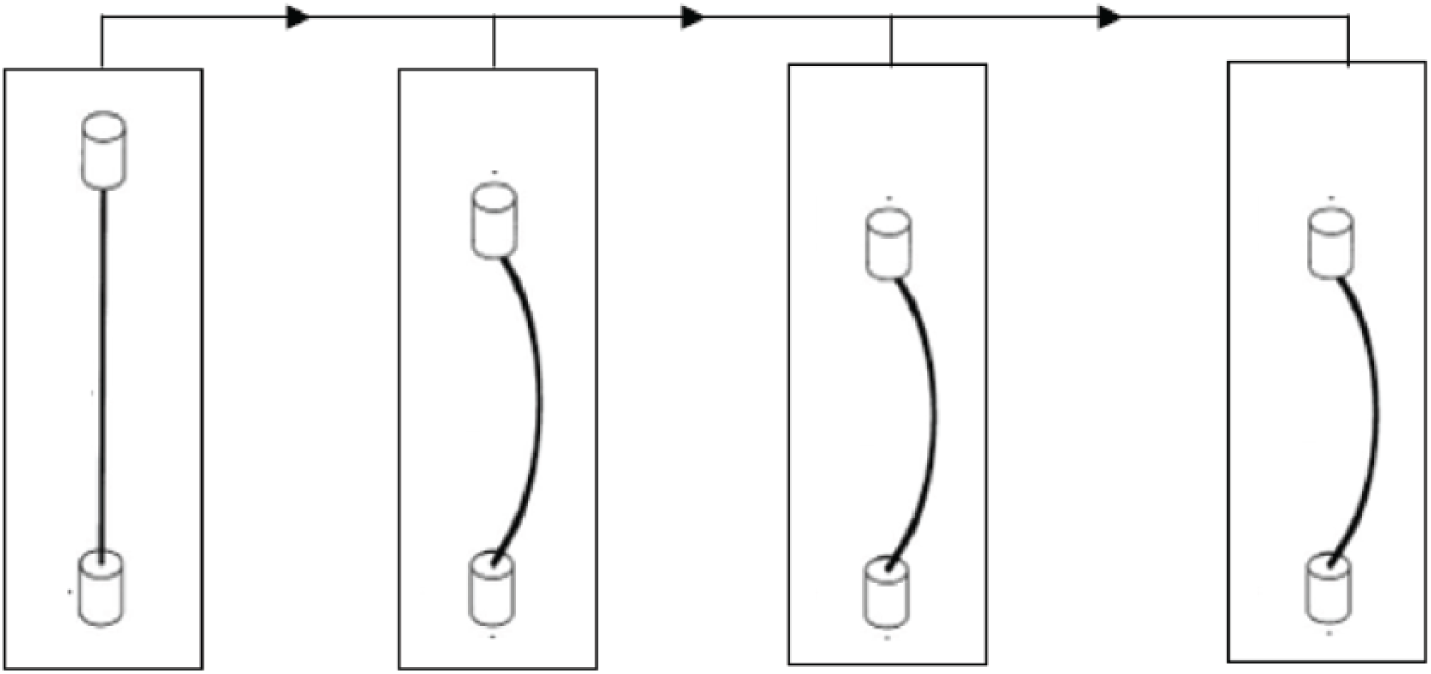
Process of the test. Before compression, the bundles are kept upright. The height of the bundles decreases gradually as the test goes on.
Hollow monofilament bundle with 10 monofilaments and compressive gauge length of 10 mm is selected for the analysis. According to the procedure, the compression graph, Figure 6(a), can be divided into two parts. Figure 6(b) shows the first part, when the load is higher, there will be a maximum stress. While in the second part, as shown in Figure 6(c), the relationship between strain and stress is similar.

Compression graph. (a) Compression graph of hollow monofilament bundles, (b) the first part, (c) the second part, and (d) height-cycle graph of hollow bundle.
The first part can be divided into three stages. In the first stage, the bundles are kept upright under the axial load. The stress increases linearly with the strain, which leads the bundle to bend soon. Therefore, this stage is very short. In the second stage, the bundle bends with good resilience. The stress increases linearly with the strain, and a maximum stress appears. In the third stage, the bending of the bundles continues and becomes excessive. The resilience failed with the decrease in the stress. The second part shows that the starting point of the strain moves backward gradually, and the maximum stresses decrease as the cycles increase.
In fact, the starting point gives the height of the specimen. The initial height, relaxed height, and recovery height of cycles are recorded. In one cycle, initial height means the height of specimen before compression. Relaxed height is measured the moment the plate leaves the specimen. And recovery height is measured after compression for a while. Recovery height can be also defined as the initial height of the next cycle. Figure 6(d) indicates that all the heights decrease as the cycles increase. The decrease in the height shows that the bundles fall into fatigue state gradually. The heights drop fast in the first five cycles. The possible reason is that the bundles are upright and can be easily out of balance under axial load at first. As the cycles increase, the bundles enter a new balance condition and the drop slows down. Differences between initial and relaxed height is stable, while the differences between initial and recovery height reduce and tend to zero.
Solid polyester monofilament bundles with identical numbers, gauge length, as well as external diameter of 0.2 mm was selected for comparison. As shown in Figure 7(a), the solid polyester monofilament bundles appear to give larger stress and smaller strain than hollow monofilament ones with identical compressive gauge length containing equal numbers of monofilaments of the same external diameter The height of the solid bundles decreases as the cycle increases, as shown in Figure 7(b). The heights drop fast in the first five cycles and the drop slows down. Differences between initial and relaxed height are stable, while the differences between initial and recovery height reduce and tend to zero. The figures show that hollow fraction only affects the values of strain and stress not the compression and deformation mechanism of monofilament bundles.

(a) Compression graph of solid and hollow bundles and (b) height-cycle graph of hollow and solid bundle. Hollow shape represents hollow monofilament and solid shape represents solid one.
For further comparison of solid and hollow bundles, relationship of compression work and cycle is introduced here. Compression work is defined as the work of the compressive load. As shown in Figure 8, the compression work of solid bundles give larger than hollow ones, which means the compressive load did more work to compress. Therefore, solid monofilament bundles have better compression resistance.

Compression work: cycle graph.
Conclusion
Tensile properties of hollow and solid monofilament are compared. Hollow monofilament with 0.2 mm external diameter and 25% hollowness demonstrates smaller tensile force and tensile strength than solid monofilament with identical external diameter. The breaking elongation and Young’s modulus are higher than solid one. The broken mechanism of hollow monofilament is determined by the manufactured methods, especially the shape of the nozzle holes in the spinneret. Compressive behavior and properties of hollow monofilament bundles were performed in this study. Hollow and solid monofilament bundles have been compared. It has shown that hollow fraction of hollow monofilament only influences the values of strain and stress not the compression model. With identical numbers, gauge length, as well as external diameter of 0.2 mm, solid monofilament bundles have better compression resistance than hollow ones. Further work will be devoted to study the effect of different hollowness of hollow monofilament on compressive properties, including identical external diameter with different hollowness and identical hollowness with different external diameters, and the application of hollow monofilaments on warp-knitted spacer fabrics.
Footnotes
Declaration of conflicting interests
The author(s) declared no potential conflicts of interest with respect to the research, authorship, and/or publication of this article.
Funding
The author(s) disclosed receipt of the following financial support for the research, authorship, and/or publication of this article: This work was supported by the Applied Foundation Research Funds of China Textile Industry Association (J201604), the Open Project Program of Hubei Key Laboratory of Advanced Textile Materials & Application, Wuhan Textile University (Fzxcl2017013), and a project funded by the Priority Academic Program Development (PAPD) of Jiangsu Higher Education Institutions.