
Abstract
This study investigated the impact and post-impact behavior of different layer weft plain knitted composite materials based on modified ultra-high-molecular-weight polyethylene/epoxy composites. The modified ultra-high-molecular-weight polyethylene weft plain knitted composites with 8, 12, 16 layers were prepared by vacuum-assisted resin transfer molding process and then subjected to impact and post-impact compression test. The impact properties were analyzed using the contact force–deflection and energy–time curves, and the post-impact compression was analyzed using the compression strength–strain curves. It can be obtained that the maximum contact force, absorbed energy, and residual compression strength after impact of the 16-layer specimen are 81.40%, 74.18%, and 73.25% more than those in the 8-layer specimen. respectively. According to the ultrasonic C-scan tests for the impact samples, the 16-layer specimen had the least damage area after the impact test, and the 8-layer composites damage area was 117.45% more than the 16-layer specimen.
Keywords
Introduction
Composite materials have excellent specific mechanical properties due to their low density.1–5 Therefore, composite materials have been used in a wide range of applications such as the aerospace, automotive, defense, and sports industries.6–10 Textile fabrics have long been known as ideal reinforcements for composite applications, due to their attractive intra- and inter-laminar strengths, damage tolerance, low cost, and versatile design potential. 11 Composite laminates are mostly used for impact resistance. The structure, 12 fiber volume fraction, plate dimension,13,14 and number of fabric layers 15 of a composite have significant effects on the impact and compression after the impact behavior of composites. The use of high-performance fiber significantly affects these properties. Knitting is ideally suited for the manufacture of components with complex shapes, and a variety of materials have been demonstrated using this technique. 16 In recent years, many experts at home and abroad have studied the impact 17 and impact compression of composite materials.18,19
Pandita et al. 17 investigated the impact properties of weft-knitted fabric composites based on their fracture toughness and tensile properties. They found that because the forces required to create a delamination are higher than the ultimate impact force, knitted fabric composites do not fail in the delamination failure mode but rather in the flexural mode, either in compression at the impacted area or in tension at the bottom, opposite the impacted area.
Aktaş et al. 20 studied the effect of the impact and post-impact behavior of E-glass/epoxy composite plates. Impact tests were continued until the complete perforation of the specimens. The failure mechanisms of the damaged specimens were evaluated for different impact energies by comparing the load–deflection curves and images of the damaged samples taken from both the impacted and non-impacted sides. The test results of these impact and post-impact tests showed that the minimum contact force was observed in the eight layers of plain fabric, and the compression after impact (CAI) strength was reduced by increasing the impact energy.
Aoki et al. 21 investigated the effect of thickness on impact-induced damage and CAI characteristics for a conventional aerospace-grade carbon fiber reinforced polymer (CFRP) laminates. Impact test and CAI test were conducted for the laminates with different thicknesses (16ply, 24ply, 32ply, 64ply). Impact with several energies was given to the specimen to examine the effect of thickness on impact response, delamination area and size, and residual compressive strength. It was found that delamination size and shape are dependent on the thickness of specimen even under the same total impact energy. The impact energy normalized by the thickness also provides different delamination characteristics, which depends on the stiffness of the laminates.
Cao et al. 22 studied the mechanical and friction properties of an ultra-high-molecular-weight polyethylene (UHMWPE) fiber/basalt fiber composite. After incorporating the basalt fiber, the impact toughness and wear resistance of the composite materials increased.
Ishikawa et al. 23 performed CAI tests on the sample. And the test has been conducted for quasi-isotropic thick plates with 48 plies by using the NASA method and on plates with 32 plies by using the SACMA method. Numerical predictions of initial buckling stress have been obtained by modeled geometry of the delaminated region simplified from its precise structure clarified by ultrasonic C-scanning. They agree fairly well with the experimental results. The in-plane stress distribution in the delaminated region before initial buckling is measured by an infrared stress graphic system.
Some researchers have studied the effects of impact energy,24,25 impactor shape,26,27 and impactor mass28–30 on the impact behavior of composite plates. There have been numerous reports on the impact behavior of glass/epoxy composites, carbon/epoxy composites, and other types of composites. UHMWPE fiber, a third-generation fiber, has attracted considerable attention due to its low density, high strength, and corrosion- and age-resistant properties. The present work aims to study the impact and post-impact behavior of weft-knitted UHMWPE/epoxy composites with different layers.
Materials and manufacture
Materials
The reinforcing material was a 400 den UHMWPE (Dongguan Sovetl Special Rope & Webbing Co., Ltd.) conjugated filament, and its physical properties are listed in the Table 1. The weft plain structure exhibited better mechanical properties than did the two other types of weft-knitted structure (rib and cardigan).31,32 Thus, the weft plain structure was chosen as the reinforcing material. After the twisting and antistatic treatments were conducted on the filament, the fabric was smoothly knitted on an E12 LXC-252SCS computerized flat knitting machine. The wale density (wales/cm), course density (courses/cm), and areal weight (g/m2) of the fabrics are shown in Table 2. The interfacial adhesion of the UHMWPE fiber-reinforced resin was poor.33,34 A plasma treatment using a PR-3 plasma generator improved the roughness and the number of polar groups on the surface of the UHMWPE fibers.
The mechanical properties of the UHMWPE conjugated filament.

UHMWPE: ultra-high-molecular-weight polyethylene.
The physical properties of the knitted fabrics.

The resin matrices were GCC-135 epoxy resin and GCC-137 epoxy hardeners from KunShan LV XUN Chemical Materials Co., Ltd.
Preparation of the composite
To determine the effects of the layers on the composite material strength, three different layers of boards, 8, 12, and 16 ([0-/90]4s, [0-/90]6s, and [0-/90]8s), were chosen. The composite had the same material strength in the wale and course directions. An epoxy that was based on the GCC-135 resin and GCC-137 hardener was used in a mass proportion of 100:30. UHMWPE/epoxy composites with 8 plies, 12 plies, and 16 plies were produced using the vacuum-assisted resin transfer molding (VARTM) technique at room temperature over 24 h. The composite VARTM preparation process is shown in Figure 4. The fabric was significantly better impregnated by the epoxy resin in the VARTM process than in the hand lay-up process, and there were no bubbles in the composite. The composite manufacturing process is shown in Figure 1. The mechanical properties of the knitted UHMWPE/epoxy composites are shown in Table 3.
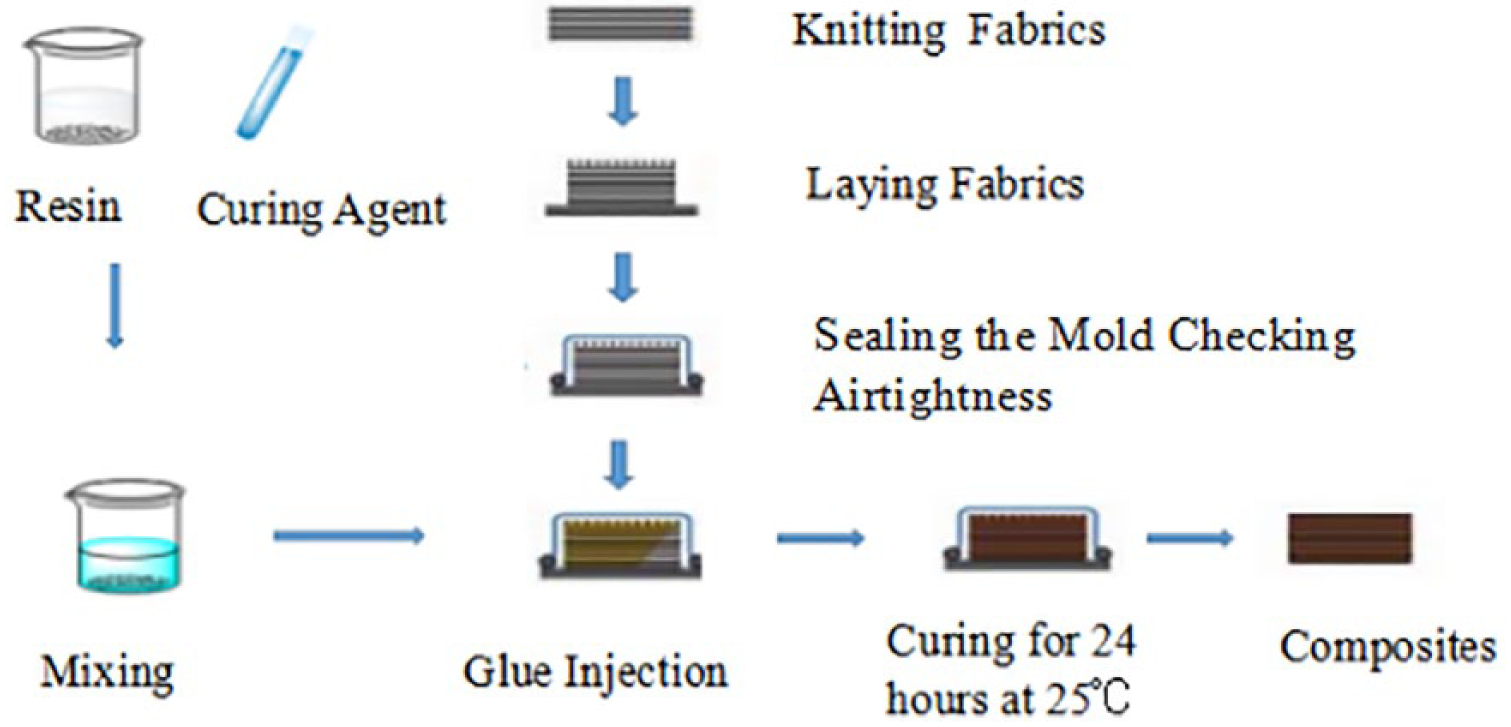
A flowchart of the vacuum resin transfer molding (VARTM) process for the composites.
The mechanical properties of the knitted UHMWPE/epoxy composites.

UHMWPE: ultra-high-molecular-weight polyethylene.
Impact tests and discussion
Impact tests
The impact tests were performed using an Instron 9250HV impact testing machine, which works based on the drop-weight method in the Key Laboratory of Advanced Textile Composites, Ministry of Education at Tianjin Polytechnic University, according to the ASTM D7136-2007 (American Standard Test Method for Measuring the Damage Resistance of a Fiber-Reinforced Polymer Matrix Composite to a Drop-Weight Impact Event) requirements. The impactor was manufactured from stainless steel and had a hemispherical nose measuring 12.5 mm in diameter. The total impact mass, including the impactor nose, crosshead, and force transducer, was 6.5306 kg. The impact test specimens were cut to 100 × 150 mm2 from composite plates using a high-pressure waterjet cutting machine. The impact tests were conducted at room temperature under different impact energies. The impact energies of composites with different numbers of layers (shown in Table 4) that were calculated according to the following formula

where E is the impact energy;
The energy levels for each knitting fabric of different layers.

Impact results and discussion
The impact behavior of the [0-/90]4s, [0-/90]6s, and [0-/90]8s weft plain knitted fabric UHMWPE/epoxy composites was investigated. Table 4 shows the impact energy levels used for the three types of composites. Figure 2(a) to (d) shows the contact force–deflection, energy–time, velocity–time, and contact force–time graphs for different layer composites, respectively.

The contact force–deflection, energy–time, velocity–time, and contact force–time curves for the composites.
Figure 2(a) shows that the maximum contact force occurs was 2.017, 3.594, and 4.992 kN for the [0-/90]4s, [0-/90]6s, and [0-/90]8s composites, respectively. The contact force–deflection curves of 12- and 16-layer composites have the same tendency. When the maximum contact force is reached, the punch is rebounded. However, for the 8-layer composites materials, when the maximum contact force is reached, the sample infiltrates because the penetration energy threshold of the 8-layer composite is lower than 17.286 J. Then, the specimen continues to receive the impact, and the material undergoes serious damage; thus, the curve fluctuates.
The contact force of the weft-knitted composites increased in a certain range with an increasing number of fabric layers. The difference in the fiber volume content between the [0-/90]8s and [0-/90]4s composites is approximately 6.56%; however, the difference in the maximum contact force is approximately 81.40%. During the low-speed impact test, the back of the specimen is stretched to suppress the destruction of its inner structure, and the higher the fiber volume content, the more obvious the effect of this inhibition.
Figure 2(b) is the energy–time curve. The absorbed energy increased to reach the maximum value with the increase in time. This result was primarily attributed to the increase in the absorbed energy due to the increase in the contact area between the impact punch and the sample. Then, the [0-/90]8s and [0-/90]6s composites rebound the punch, the material transfers a certain energy conversion to the punch, after the punch is separated from the sample, the energy keeps constant. For the eight layers of composite material, the punch did not rebound, the impact of all the energy was absorbed by the sample and maintained at a certain value.
The maximum energy absorption levels of [0-/90]8s, [0-/90]6s, and [0-/90]4s are 31.915, 25.285, and 18.323 J, respectively. The difference in the fiber volume content between the [0-/90]8s and [0-/90]4s composites is approximately 6.56%; however, the difference in maximum energy is approximately 74.18%.
Combined with the speed–time curve of the punch in Figure 2(c), note that when the punch makes contact with the specimen during the impact test, the speed begins to decrease. When impact tests were performed on 12- and 16-layer composites, the punch speed began to drop to zero and then rebounded and gradually increased until it separated from the specimen.
The curve in Figure 2(d) shows that the contact force–time curve of the 12- and 16-layer composites is approximately symmetrical at the maximum value, which indicates that the weft-knitted composite material has a certain degree of flexibility and that some deformation of the material deformation is recoverable. For the 8-layer composites, under the corresponding impact energy, the deformation of the specimen is larger than the elastic deformation, resulting in plastic deformation—the impact of the sample damage is infiltration. As shown in Figure 2(d), the greater the number of ply layers, the greater the rigidity and load-carrying capacity of the sample, but the more obvious the fluctuation due to stratification in the impact process. In addition, Figure 2(d) (8ply) shows that the lower the maximum contact force, the longer the contact time. The contact force–time curve fluctuates when penetration occurs.
Impact damage mechanism
When a foreign object impacts a composite laminate, several damage modes, including fiber splitting, fiber cracking, matrix cracking delamination, and edge delamination, can occur in the composite laminate. These damage modes depend on the impact parameters, such as the shape and mass of the impactor, the impact energy, and the dimensions of the composite laminate.
Visual inspection
Figure 3(a) to (f) shows the impact damage of the [0-/90]4s, [0-/90]6s, and [0-/90]8s composites. In the figures, the damaged areas are clearly circular, and the size of the damaged areas is nearly identical for the three types of specimens. The area of the frontal lesion on the same sample is smaller than the area on the back, and the degree of lesion on the back of the sample is gradually weakened from the central area to the surrounding area and is radially distributed. The center of the front of the sample has an approximately circular bright area due to the instant impact of the punch, the resin in the center part is pressed down by the punch; however, the degree of damage in this area is lower than that of the surrounding area, the reinforced structure transmits the load to the surrounding area, the surrounding resin generates tensile damage, and the interior of the resin generates cracks—the light cannot improve in the sample. So, under strong light, the impact of the central area of the light irradiation is brighter than that of the surrounding area.
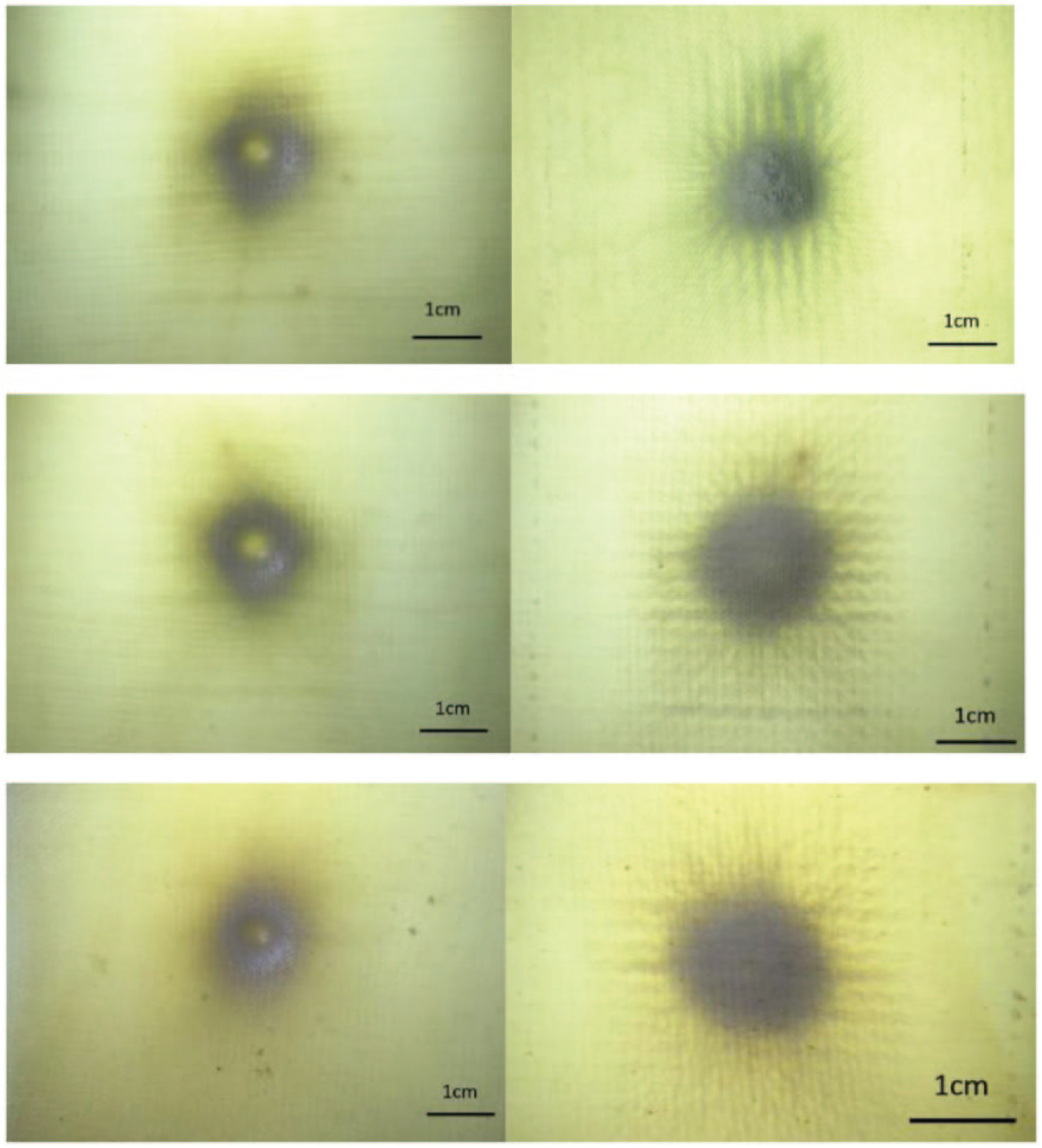
The impact damage of the 8-ply, 12-ply, and 16-ply composites. (a) 8-ply front, (b) 8-ply back, (c) 12-ply front, (d) 12-ply back, (e) 16-ply front, and (f) 16-ply back.
As observed from the back of the sample, the reinforced structure produced a certain degree of tensile deformation, which is due to the weft-knitted reinforced structure (which has a good degree of deformation and increased the fabric load deformation), while the impact damage expanded from the center outward, and the fabric bulged away from the point of impact.
A small amount of fiber splitting associated with the fiber cracking occurred on the back of the 8-layer composite material; however, there was no fiber cracking in the other impacted composite materials because of the flexibility of the weft-knitted composites, high fiber volume content, less space in the laminates, a less resin-rich area, and effective resistance to the impact load. Compared with other composite materials, eight layers of composites have fewer layers, and the load transmitted by each layer of fabric is larger. Plastic deformation occurs during the impact process, and the impact specimen is destroyed through penetration. Other composites bounce back during the impact process.
Water immersion ultrasonic C-scan tests and discussion
Water immersion ultrasonic C-scan tests
Due to the anisotropic and energy-absorbing characteristics of the composites, the composites will exhibit different damage behaviors; for example, the surface may not have obvious visual damage, and its interior may have serious internal damage due to the absorption of transient impact energy. Therefore, internal damage is an important factor in evaluating the impact properties of materials.
At present, ultrasonic imaging detection methods are widely used to detect the internal damage of materials. Ultrasound imaging is based on the principle of acoustic wave propagation. When sound waves encounter damage or defects in the medium, their propagation paths will produce differences. This path change is related to the reflection of waves by the damage in the propagation medium. Through special ultrasonic testing equipment, the composite material is scanned, and the reflected waves at each detection point are extracted to achieve ultrasonic imaging of the detection results.35,36
The water immersion ultrasonic C-scan tests of the impacted layer weft plain knitted fabrics were determined at 25°C using a BSN-C3409 ultrasonic immersion focusing C scanner at Tianjin Polytechnic University. The specimens were the composites tested through C scan after impact.
Results and discussion
The ultrasonic C-scan damage image is the result of multi-layer damage pattern superposition, which can be directly used to characterize the damage area, distribution, and expansion of the specimen. The size of the sample is 10 cm × 15 cm. Figure 4(a) to (c) shows the C-scan images, the damage calculation area for the [0-/90]8s, [0-/90]6s, and the [0-/90]4s composites after impact (The green areas are the undamaged areas in the picture, and red and yellow are the scanning areas of the label paper. The midnight blue and the light blue show the impact damage, which represents the different degrees of damage.)

The test results of the ultrasonic C-scan and area calculation for the [0-/90]8s [0-/90]6s and [0-/90]4s composites.
As shown in the diagram, the energy impact on the composite material from the center point of the impact to the surrounding area and the trend of diffusion gradually decrease until the energy is completely dissipated, differing from the impact damage of the woven composite materials.
For woven composite laminates, the interweaving of warp and weft yarns in woven fabrics inhibits cracks and reduces the possibility of delamination. However, this process also limits the propagation of stress waves in the plane. In the initial stage, the work done by the impact load is mostly used to generate damage in the local thickness direction. As the drop hammer displacement increases, the laminate mainly resists the impact load through the overall deformation. Finally, a large volume of plastic deformation is formed. From other studies, 37 we learned that the impact damage of woven composite materials is the shape of “十” and that the impact back surface is the shape of “一.” However, this situation shows that the weft-knitted reinforcement can disperse the impact stress, expand the impact range, and expand in all directions, thereby greatly reducing the local compression and improving the impact resistance of the composite material.
The impact damage area of the composites was calculated using image-Pro-plus software (unit: pixel). Figure 4(g) to (i) shows the calculation results of the damage areas for the [0-/90]8s, [0-/90]6s and [0-/90]4s composites. From the figure, we can determine that the 8-layer fabric composite damage area of 28,158 pixels is greater than the 16-layer 12,949 pixels, and the 12-layer fabric composite damage area is 15,734 pixels. The [0-/90]4s composite damage area is 117.45% more than that of [0-/90]8s. The [0-/90]6s composite damage area is 78.96% more than that of [0-/90]4s, and the [0-/90]6s damage area is 21.51% more than that of [0-/90]8s.
With an increase in the number of layers, the impact strength of each layer is smaller, the impact damage of each layer is smaller, and the damage degree of the composite material is lower. Therefore, the impact resistance is better.
CAI test
The CAI behavior of the impacted layer weft plain knitted fabrics was determined at room temperature using an Autograph Shimadzu material testing machine at Tianjin Polytechnic University, according to ASTM D7137-2007. To prevent the specimens from buck-ling under the compressive load, they were supported laterally. The compressive load was applied from top to bottom at a displacement rate of 1.5 mm/min (Figure 5). During the CAI tests, the force versus displacement history was recorded with a data acquisition system.

Testing after impact compression.
CAI results and discussion
As shown in Figure 6, the CAI damage of three kinds of composites demonstrated smother damage. The figure shows that the CAI damage starts around the impact damage. The damage area was distributed symmetrically. In addition, as shown in the figure, serious damage occurs in the AB position, and many stratification phenomenon occurs. The A position is more serious than the B position. The C position shows less compressive damage after impact, and just have a little stratification, because as the thickness of the composite material increases, the degree of bending of the material after impact decreases; the residual compressive strength increases after impact. These results show that the compressive stress strongly depends on degree of deformation after impact (i.e. the number of fabric layers or the thickness of the fabric layer).
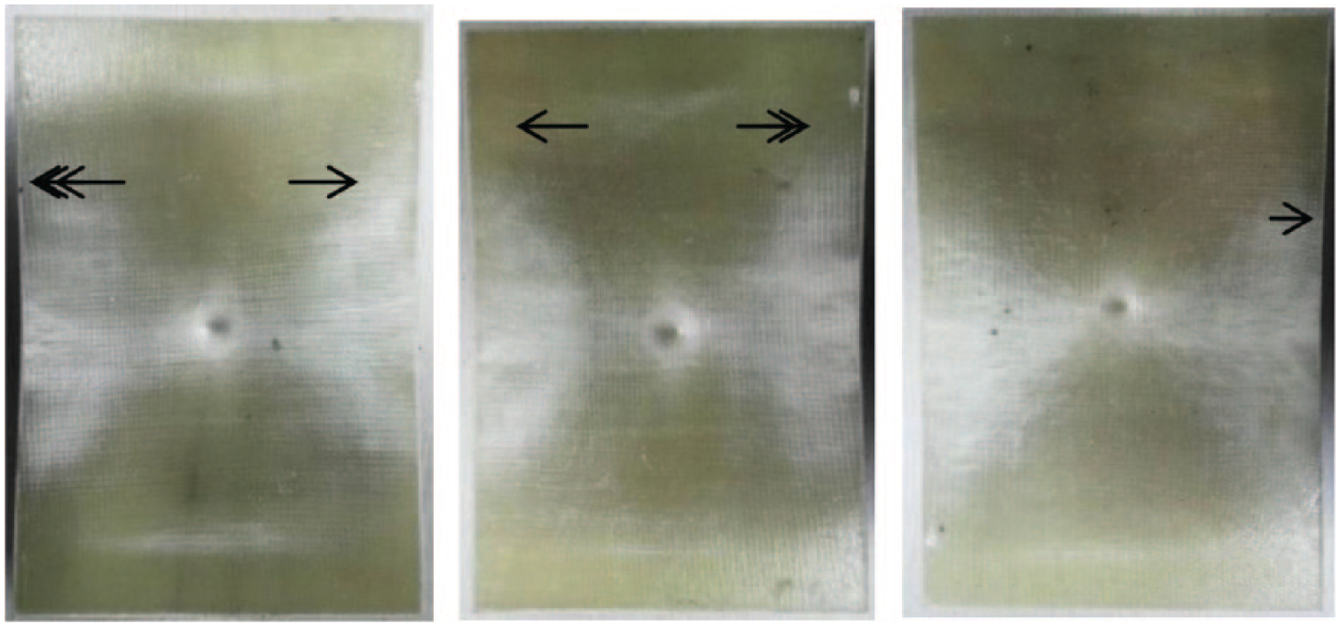
The CAI damage to the front.
At the beginning of the CAI test, the force–deflection curves (Figures 7(a) to (c)) were nonlinear. Then, the curves became linear, and the force increased as the CAI test continued. The linear fittings of these parts of the curves exhibited R values of approximately 0.99. The failure load of the impacted samples was obtained from the force–deflection curve. The first load, which was reached in the nonlinear part of the force–deflection curve, was accepted as the critical CAI load. The CAI strengths of the specimens were calculated by dividing the critical CAI load by the cross-sectional area of the samples.28,38 The compression stress–strain curve is shown in Figure 7(d).

(a–c) The compression force–deflection curves for the [0-/90]4s, [0-/90]6s, and [0-/90]8s composites. Compression strength–strain curves loading is shown in (d).
The compression stress of [0-/90]8s is 41.64% more than that of the [0-/90]6s sample, which is 73.25% more than that of the [0-/90]4s sample. This is because as the number of layers increases, the impact deformation decreases, and the remaining compressive strength increases.
Conclusion
This study investigated the impact and post-impact behavior of weft plain knitted composite materials based on UHMWPE/epoxy. The conclusions can be summarized as follows.
The maximum contact force in the impact test increased with the number of layers of fabric for the same composite structure in a certain range.
Penetration occurred for the [0-/90]4s specimen at 17.2 J, while rebounding occurred at 24.522 and 31.356 J for the [0-/90]6s and [0-/90]8s specimens, respectively, as indicated by a velocity of 0 m/s.
The damaged areas in the three types of specimens were circular. The impact damage expanded from the center outward.
With an increase in the number of plies, the area of impact damage decreased. The C scan showed that the [0-/90]4s damage area is 117.45% more than [0-/90]8s.
The middle sections of the force–deflection curves were linear, unlike the beginning and final parts of the CAI test. The compression force increased as the number of layers increased.
The compression stress of [0-/90]8s is 41.64% more than the [0-/90]6s sample and is 73.25% more than the [0-/90]4s sample.
Therefore, the low-intensity impact stress wave is effectively propagated while increasing the in-plane strength and rigidity. Thus, the impact energy is dissipated, and the presence of the weft-knitted fabric increases the bending stiffness and interlayer toughness and suppresses the generation of stratification.
Footnotes
Declaration of conflicting interests
The author(s) declared no potential conflicts of interest with respect to the research, authorship, and/or publication of this article.
Funding
The author(s) disclosed receipt of the following financial support for the research, authorship, and/or publication of this article: This work was supported by the National Natural Science Foundation of China under Grants Number 51403154 and 11602168.