
Abstract
High-speed centrifugal spinning is a novel method to fabricate nanofiber. It has the potential to fabricate nanofiber on a large scale because its production efficiency is much greater than traditional methods. Nozzle is an important part of high-speed centrifugal spinning equipment because its length, shape, and diameter all will affect the morphology and quality of nanofiber. It is useful to study the movement and forces of spinning solution in the nozzle. In this article, the principle and equipment structure of high-speed centrifugal spinning are briefly introduced at first. Then the movement and forces of spinning solution are analyzed by establishing parametric model at nozzle. It can be found that the spinning solution is ejected from nozzle when the rotating speed reaches a critical value. The critical rotating speed is inversely proportional to the radius of nozzle and directly proportional to the viscosity of spinning solution. There are several nozzle structures proposed and compared for nozzle optimization. Finally, the effects of nozzle parameters, concentration of spinning solution, and rotational speed on the morphology of nanofiber are verified by high-speed centrifugal spinning experiments. It lays the foundation for optimizing spinning equipment.
Introduction
There are many traditional methods to fabricate nanofiber, such as electrospinning, centrifugal electrospinning, and melt blowing method.1–3 Electrospinning and centrifugal electrospinning are common methods. But both of these methods require a high-voltage electrostatic field, and their production efficiency is low. With the rapid development of nanotechnology, more and more researchers are committed to optimize the method of nanofiber fabrication. In order to improve the production efficiency of nanofiber, there is a more efficient method proposed, called high-speed centrifugal spinning.4,5 Its production efficiency can reach 1 g/min. High-speed centrifugal spinning is different from traditional methods. 6 It not only overcomes the inherent defects of traditional methods but also fulfills the demand for fabrication nanofiber on a large scale.7–9 So many researchers paid attention to study and optimize the high-speed centrifugal spinning.10,11 McEachin and Lozano 12 found that the morphology of nanofiber was affected by rotating speed when they fabricated polycaprolactone nanofiber via high-speed centrifugal spinning. Vazquez et al. 13 studied the effect of spinning solution concentration on the morphology of nanofiber.
The factors affecting the quality of nanofiber could be divided into two categories: one is internal factors, such as spinning solution properties, the other is external factors, such as equipment parameters and environmental factors. 14 Lu et al. 15 fabricated polyacrylonitrile (PAN) nanofibers by selectively varying parameters. They found that the final morphology of nanofiber was affected by the collection distance, nozzle rotating speed, and spinning solution concentration. Sun et al. 16 summarized the factors affecting the final morphology of nanofiber in the process of high-speed centrifugal spinning. These studies provide a theoretical basis for optimizing the equipment of high-speed centrifugal spinning. They are helpful to fabricate high-quality nanofibers. At present, the nanofibers which are fabricated by centrifugal spinning have been used in many fields. Loordhuswamy 17 prepared highly aligned fibrous scaffolds for tissue regeneration. They presented that the centrifugal spinning mat was more suitable for tissue engineering applications. Zuniga et al. 18 studied the electrochemical performance of multichannel TiO2/Carbon composite nanofibers which were fabricated by forcespinning technology. Although nanofibers prepared by centrifugal spinning have found proper applications. The movement and forces of spinning solution have not been studied in more detail. In particular, the nozzle as an important part of high speed centrifugal spinning equipment, its length, internal structure and diameter will affect the movement of spinning solution and jet. Studying the movement and forces of spinning solution in nozzle is conducive to improve the quality of nanofiber and optimize the spinning equipment.
The principle of high-speed centrifugal spinning is introduced briefly in this article. Then this article studies the movement and forces of spinning solution by establishing parametric model at nozzle. The critical rotating speed, which is required for spinning solution to be ejected from nozzle, is also studied. Several nozzle structures are proposed and compared for optimizing the spinning equipment.
Finally, high-speed centrifugal spinning experiment is carried out, and some conclusions are given.
The principle of high-speed centrifugal spinning
High-speed centrifugal spinning method is different from traditional nanofiber fabrication method because it fabricates nanofiber utilizing centrifugal force. 19 Its equipment is mainly composed of a driving motor, a container for storing spinning solution, a nozzle, and a collection device.20,21 The equipment of high-speed centrifugal spinning is shown in Figure 1. The container and nozzle are rotated by the motor, and their rotating speed can be adjusted by changing the motor speed. The spinning solution is placed in the container. It rotates with the container in the process of fabricating nanofibers. The centrifugal force is generated by rotating spinning solution and it is the most driving force for fabricating nanofiber. 22 The collector is fixed in the surrounding to collect nanofibers.

Equipment sketch of high-speed centrifugal spinning.
The spinning solution flows in the container and nozzle when motor starts running. There is a critical rotating speed which is determined by the parameters of spinning solution and equipment. 23 When the motor speed is increased to the critical speed, the forces of spinning solution are balanced. 24 An ellipsoidal spinning solution cone is formed at the nozzle. The ellipsoidal cone is similar to the Taylor cone in electrospinning. 25 The spinning solution will be ejected from the nozzle when motor speed is greater than the critical speed. Then a spinning jet is formed. There is a spherical droplet at the head of spinning jet. The jet moves under the action of droplet traction. The jet is stretched during movement; its diameter becomes smaller and surface becomes smoother. 26 When the jet rotates several cycles, a stable rotation trajectory is formed, 27 as shown in Figure 2. At the same time, the nanofiber is fabricated because of solvent evaporation and jet cooling. Finally, the nanofiber is collected by surrounding collection device. 28 The schematic diagram of high-speed centrifugal spinning is shown in Figure 3.

Process of spinning solution ejection: (a) spinning solution at nozzle, (b) solution cone is formed, (c) droplet at the top of spinning solution, (d) necking appeared, (e) unstable stage, and (f) stable stage.

Schematic diagram of high-speed centrifugal spinning.
The spinning solution is ejected from the nozzle to form a jet when the centrifugal force of spinning solution is greater than the surface and viscous force in the process of high-speed centrifugal spinning. 29 The surface tension and viscous force depend on the properties of spinning solution. The centrifugal force depends on the equipment parameters.30,31 Studying the influence of these parameters on nanofiber fabrication is necessary. These studies could help to improve the quality and morphology of nanofiber. It is even possible to fabricate nanofiber with specified morphology.
The movement and forces of spinning solution in the nozzle
According to the principle of high-speed centrifugal spinning, nozzle is an important part of high-speed centrifugal spinning equipment. Studying the forces and movement of spinning solution in nozzle is useful to improve nanofiber quality. Therefore, a parametric model is established at nozzle. It helps to analyze the forces and movement of spinning solution in nozzle.
As shown in Figure 4, the origin O is on the axis of drive shaft. The O1 is along the axis of nozzle. The ω is the rotation angular velocity. The spinning solution is underwent gravity, static pressure, viscous force, and surface tension when the motor is not rotating. The gravity along the vertical direction could be ignored. Because the static pressure of spinning solution is small, it is not enough to overcome the viscous force; spinning solution is still stationary in nozzle at this time.

The coordinate system of nozzle.
The motor accelerates from standstill. The centrifugal force increases gradually as the rotating speed increases. The spinning solution begins to flow in nozzle when the resultant force of static pressure and centrifugal force is greater than viscous force of spinning solution. The flow of spinning solution could be divided into two regions: one is flow core zone and the other is flow gradient zone, as shown in Figure 5.

Schematic diagram of spinning solution velocity distribution.
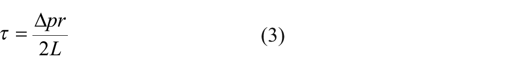
There is an equation

where ∆p
The formula for radius of the flow core zone is

The radius of flow core zone will decrease gradually when the centrifugal force increases. Eventually, the flow core zone gradually disappears, and the flow gradient zone fills the entire nozzle. The flow of spinning solution in the nozzle becomes laminar, as shown in Figure 6.

Diagram of spinning solution laminar flow.
When the movement of spinning solution in the nozzle is laminar, the formula for viscous force of spinning solution is as follows
Because the spinning solution is a non-Newtonian fluid, the formula is as follows
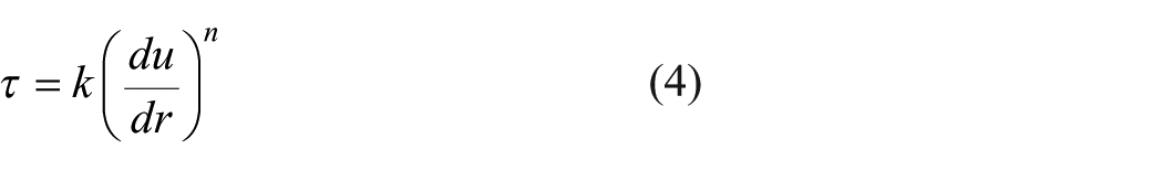
where du is the current velocity of spinning solution in the nozzle, dr is the nozzle radius, k is consistency coefficient of spinning solution, and n is rheological index.
Substituting equation (3) into equation (4)

The current velocity of spinning solution declines from u to 0 from nozzle axis to nozzle wall. Coordinate system at nozzle cross-section is shown in Figure 7. The current velocity of any point in nozzle could be expressed.

Coordinate system at nozzle cross-section.
Point A is any point on the nozzle section. The position of point A is expressed as

The radius at point A is

The current velocity of spinning solution at point A is

The flow of spinning solution in nozzle is

where R is nozzle radius.
The average current velocity of spinning solution in nozzle is

When the motor speed increases, the average current velocity of spinning solution will increase. The spinning solution flow will change to turbulence when the Reynolds number reaches a critical value.
The Reynolds number of spinning solution is

When the flow of spinning solution in the nozzle is turbulent, the flow of spinning solution can be divided into three zones, viscous bottom layer, transition zone, and turbulence zone, as shown in Figure 8.

Turbulent flow of spinning solution.
Analyzing the movement of spinning solution in nozzle could help to study the forces of spinning solution in the process of high-speed centrifugal spinning. It provides theoretical basis for nozzle optimization. In addition, studying the critical speed, which required for spinning solution to be ejected from nozzle, is also helpful to fabricate better quality nanofiber.
The formula of spinning solution motion in nozzle is

where dV is the current velocity of spinning solution, ρ is the spinning solution density,
According to the continuity equation of spinning solution in nozzle

The density of spinning solution is constant, so


According the principle of high-speed centrifugal spinning, spinning solution is mainly underwent to centrifugal force, static pressure, viscous force, and surface tension when it is ejected from nozzle. The centrifugal force and static pressure are the driving forces, while the viscous force and surface tension are the resistance forces. When the solution cone is formed at nozzle, the centrifugal force, static pressure, viscous force, and surface tension are balanced along the axis of nozzle. So the forces of spinning solution in the nozzle could be simplified, as shown in Figure 9. The R is the radius of nozzle and the L is the length. The R0 is the distance between the nozzle and the rotation axis.
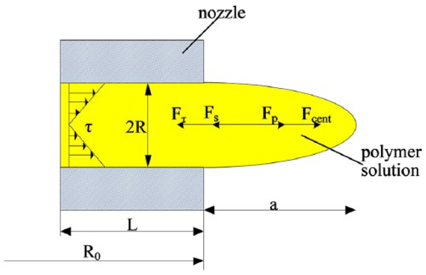
Schematic diagram of the forces of spinning solution.
The formula for the force balance along the axis of nozzle is written as follows

where
The spinning solution is stored in container and nozzle in the process of high-speed centrifugal spinning. Nozzle is connected to container. There is a liquid-level difference between the spinning solution in the container and nozzle. So the spinning solution will be underwent to static pressure

where h is the liquid-level difference, and A is the area of nozzle section.
The viscous force of spinning solution along the axis of nozzle is

where A1 is the contact area between spinning solution and nozzle, k is consistency coefficient of spinning solution, n is rheological index,
According to the continuity equation of spinning solution
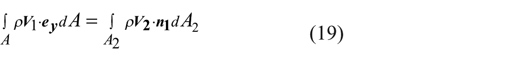
where ρ is spinning solution density,
Substituting equation (18) into equation (19), the viscous force of spinning solution is

Because an ellipsoidal droplet will be formed at the tip of nozzle before spinning solution is ejected from nozzle. The surface tension of spinning solution is generated on the cone surface.
As shown in Figure 10, R is the radius of nozzle, l is the length of spinning solution edge, θ is the angle between surface tension and the vertical direction, and F1 and F2 are the components of surface tension
where σ is the surface tension coefficient of spinning solution.
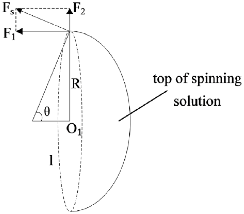
The surface tension of spinning solution.
The two components are


The length of spinning solution edge is

The component force F2 will cancel each other out along the spinning solution edge. There is only the component force in the horizontal direction eventually.
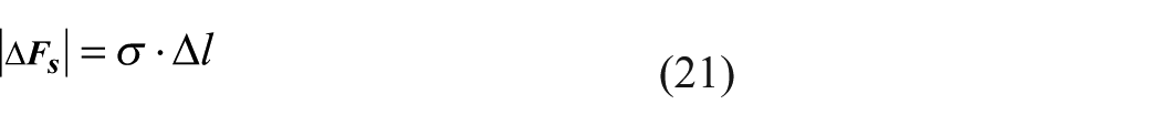
The surface tension of spinning solution along the nozzle axis is written as follows

The centrifugal force of spinning solution consists of two parts. One is the centrifugal force of spinning solution in nozzle, and the other is the centrifugal force of spinning solution cone.
The centrifugal force of spinning solution in nozzle is
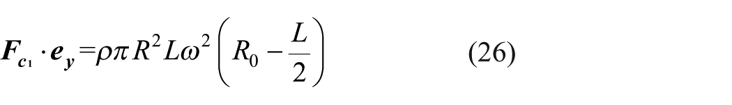
where R is the radius of nozzle, L is the length of nozzle, R0 is the distance from the end of nozzle to rotation axis, and ω is nozzle rotation angular velocity.
The centrifugal force of spinning solution cone is written as follows

where a is the length of spinning solution cone.
So the formula for the centrifugal force is as follows

Finally, the relationship between critical angular velocity and experimental parameters in the process of high-speed centrifugal spinning can be derived. The critical angular velocity is
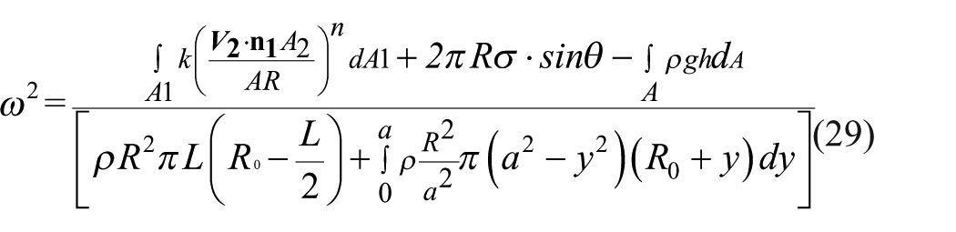
According to equation (29) and above derivation, the critical angular velocity required for spinning solution to be ejected from nozzle can be initially determined. The critical angular velocity is mainly related to parameters of spinning solution, rotating radius, nozzle diameter, and so on. It is inversely proportional to the radius of nozzle and directly proportional to the viscosity of spinning solution. Studying the forces and movement of spinning solution in the nozzle helps to determine the required rotating speed in advance. It not only provides theoretical basis for nanofiber fabrication but also facilitates the optimal design of high-speed centrifugal spinning equipment.
Internal structure of nozzle
The spinning solution flows from container into nozzle under the action of centrifugal force. Then the spinning solution is ejected from nozzle to form a jet. The role of nozzle in high-speed centrifugal spinning is to transport spinning solution, reduce the initial diameter of the jet, and stabilize the flow of spinning solution. The initial diameter of jet is determined directly by the diameter of nozzle. The flow of spinning solution in the nozzle also affects the initial diameter of the jet. If the flow direction of spinning solution is disordered, the jet will expand. It will increase the nanofiber diameter.
Cylindrical nozzle
The cylindrical nozzle is the most common in the process of high-speed centrifugal spinning at present. The length of nozzle can be selected from 1 to 3 cm, and the diameter of nozzle is generally 0.2, 0.4, 0.6, 0.8, and 1 mm. When the spinning solution flows into nozzle from container, the flow of spinning solution will become disordered. So the nozzle needs a certain length to smooth the flow of spinning solution.
It can be known from equation (3) that the viscous force of spinning solution is related to the diameter and length of nozzle. When the current velocity of spinning solution is constant, the viscous force of spinning solution is inversely proportional to the radius of nozzle and is proportional to the length of nozzle. So optimizing the nozzle is useful to reducing the viscous force of spinning solution and the rotating speed.
Stair-stepping nozzle
The viscous force of spinning solution decreases as the diameter of nozzle increases. So there is stair-stepping nozzle put forward. The initial diameter of stair-stepping nozzle is larger, which could reduce the viscous force of spinning solution. The smaller diameter at the end of nozzle could reduce the initial diameter of jet. Compared to cylindrical nozzle, the stair-stepping nozzle could reduce the viscous. However, it increases the instability of spinning solution flow and causes additional energy losses. Energy loss mainly occurs at the contraction section B, as shown in Figure 11.

Stair-stepping nozzle.
The energy loss of spinning solution at the contraction section B is

where A1 and A2 are cross-sectional areas, and v2 is the flow rate of spinning solution at the cross-section A2.
It causes energy loss because the stair-stepping nozzle inner diameter reduces suddenly. However, the total energy loss of spinning solution in stair-stepping nozzle is less than in cylindrical nozzle. So the stair-stepping is conducive to fabricate nanofiber.
Tapered nozzle
The principle of tapered nozzle is similar to that of stair-stepping nozzle. The tapered nozzle diameter decreases gradually from the inside to the outside along the nozzle. It can not only reduce the viscous force of spinning solution but also stabilize the flow of spinning solution. The schematic diagram of tapered nozzle is shown in Figure 12.

Tapered nozzle.
Because the nozzle diameter gradually reduces, there is also an additional energy loss when the spinning solution flows in the tapered nozzle. The energy loss of spinning solution is
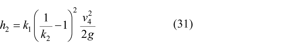
where k1 and k2 are scale factors. k1 is related to the inclination angle β of the tapered nozzle inner wall. k2 is related to the cross-sectional area ratio of A4 and A3, and v4 is the spinning solution flow rate at the end of the tapered section.
The energy loss occurs in both stair-stepping nozzle and tapered nozzle because of the change of diameter. However, the energy loss in the tapered nozzle is smaller and the flow of spinning solution is smoother. So the tapered nozzle is also conducive to high-quality nanofiber fabrication.
Streamlined nozzle
In the process of high-speed centrifugal spinning, the flow of spinning solution is disturbed when the nozzle direction is inconsistent with the flow direction of spinning solution. So the streamlined nozzle is put forward. Although the movement of spinning solution in the nozzle is complex, the flow direction of spinning solution can be determined by the pressure distribution of nozzle. According to the pressure distribution in the nozzle, the internal structure of nozzle is designed to be streamlined. It could greatly stabilize the flow of spinning solution and reduce the resistance.
In addition, the pressure distribution uniformity of spinning solution at the nozzle section can be improved by changing the angle of nozzle outlet. When the movement direction of the initial jet coincides with the direction of the nozzle outlet, the jet moves more smoothly in the air; it helps the jet to stretch.
High-speed centrifugal spinning experiment
There are many kinds of spinning solutions to fabricate nanofibers.9,32 Nanofibers fabricated from different solutions have unique properties and applications. 33 PAN is a common material for fabricating PAN nanofibers. PAN nanofibers are widely used in high performance composite materials, filter materials, tissue engineering, and so on,34,35 especially they can be used to fabricate carbon nanofibers. 36 Therefore, PAN is selected as the material for high-speed centrifugal spinning in this experiment: observing PAN nanofiber fabrication process and studying the factors affecting the morphology of PAN nanofibers through the experiment.
PAN nanofiber fabrication
The PAN is dissolved with a suitable solvent and the PAN solutions are fully stirred by magnetic stirring apparatus at room temperature for 24 h. In the experiment, PAN solutions with different concentrations from 2% to 15 wt% are prepared to fabricate PAN nanofibers. There are a series of nozzles with different diameters (0.2, 0.4, 0.6, and 0.8 mm). The speed of direct current motor can be controlled from 0 to 8000 r/min. PAN nanofibers are fabricated by adjusting nozzle diameter, PAN solution concentration, and motor speed. The experimental results show that the PAN solution is ejected from nozzle when motor speed increases to the critical speed. After the PAN solution is ejected from nozzle, the movement of jet is stable gradually with the increase of rotating speed. The jet becomes finer and finer, and PAN nanofibers are fabricated with the jet elongation and the solvent evaporation. Finally, PAN nanofibers reach the collection device and are collected.
Experimental results and conclusions
The PAN nanofibers fabricated by different PAN solution concentrations and equipment parameters are collected and compared. It is found that there is no nanofiber formed when the PAN solution concentration is lower than 7 wt%. As the PAN solution concentration increases, there are a little nanofibers and beads formed. Because the viscosity of spinning solution is low, the jet is discontinuous. The beads are formed under the action of surface tension. When the concentration increases to 10 wt%, there are lots of continuous nanofibers and beads formed, as shown in Figure 13. The number of beads decreases as the concentration increases. However, the average diameter of PAN nanofibers will increase when concentration increases, as shown in Figure 14.

The scanning electron microscope image of PAN nanofibers fabricated from 10 wt% solution using 0.4 mm nozzle.

Influence of PAN solution concentration on average diameter of PAN nanofibers.
The nozzle diameter also affects PAN nanofiber diameter. The average diameter of PAN nanofibers fabricated from 12 wt% solution using different nozzles is shown in Figure 15. Nanofiber diameter increases as nozzle diameter increases.

Influence of nozzle diameter on average diameter of PAN nanofibers.
Rotating speed is an important factor in determining the morphology of PAN nanofibers. The PAN nanofibers are fabricated by high-speed centrifugal spinning from 12 wt% PAN solution using 0.4 mm nozzle at different rotating speed. The average diameter of PAN nanofibers fabricated by different rotating speed is shown in Figure 16. When the rotating speed increases from 2000 to 4000 r/min, the average diameter of PAN nanofibers decreases from about 580 to 400 nm. But if the rotating speed is too high, the jet is broken and PAN nanofibers are discontinuous.

Influence of rotating speed on average diameter of PAN nanofibers.
It is easier to fabricate PAN nanofiber when the PAN solution concentration is 12 wt% and the nozzle diameter is 0.4 mm. At this time, the rotating speed is smaller, the diameter distribution of nanofibers is most uniform, and the average diameter is smaller, about 400 nm. The nanofiber image obtained by scanning electron microscope is shown in Figure 17.

The scanning electron microscope image of PAN nanofibers fabricated from 12 wt% solution using 0.4 mm nozzle.
The experimental results show that the spinning solution concentration, nozzle diameter, and rotating speed all affect the diameter distribution of PAN nanofibers. Among these factors, the nozzle diameter and rotating speed have a greater effect on the PAN nanofibers. When the concentration of spinning solution is between 10 and 12 wt%, the change of PAN nanofiber diameter is not obvious.
Conclusion
This article mainly analyzes the movement and force of spinning solution in the nozzle. In addition, the relationship between equipment parameters and critical rotating speed is explored. It provides a theoretical basis for nanofiber fabrication and equipment optimization. However, there are many questions in high-speed centrifugal spinning that need to be studied and improved. The movement of spinning solution in the container is not analyzed. The force of spinning jet in air and the effect of solvent parameters on nanofiber diameter are not studied. Besides, the motor speed is still very high, which is dangerous. Therefore, high-speed centrifugal spinning has great potential for improvement. The application of high-speed centrifugal spinning in industry will be more extensive with the further improvement and perfection.
Footnotes
Declaration of conflicting interests
The author(s) declared no potential conflicts of interest with respect to the research, authorship, and/or publication of this article.
Funding
The author(s) disclosed receipt of the following financial support for the research, authorship, and/or publication of this article: This study was funded by the National Natural Science Foundation of China (Grant 51775389) (Funder ID: 10.13039/501100001809).