
Abstract
The ventilation of the microclimate air of the clothed human body segment is a result of (1) the air flow from the environment through the clothing open apertures, (2) the penetration of the porous clothing, or (3) air flow originating in the microclimate of the other clothed body parts. The microclimate air flow at the connections of clothed segments is named the inter-segmental ventilation and constitutes a real physical boundary condition that leads to ventilation of connected segments. In this study, a simplified electric circuit model is developed to estimate clothing ventilation based on the analogy between the air flow in the microclimate air layer and an electric circuit composed of resistance and inductance elements. The model takes into account the inter-connection between the segments for the clothed human upper part driven by difference of pressure in the microclimate air of the trunk and the upper arms. The developed model is validated using the tracer gas method applied on a walking manikin placed in a climatic chamber under windy conditions. Good agreement was found between predicted segmental ventilation and the experimental values with a maximum error of 16%. It was found that the inter-segmental ventilation is significant at high relative velocity for permeable clothing and increased with the increase in the relative velocity constituting about 30% of the arm ventilation and 14% of the trunk ventilation.
Keywords
Introduction
Clothing is designed to provide the thermal comfort of the wearer. 1 The thermal comfort is achieved by allowing the clothing ventilation in hot climates and blocking it in cold climates. 2 In its turn, the air ventilation of the human body through clothing has a major effect on thermal comfort and static/dynamic insulation values of clothing ensembles.3–8 The main reason is that clothing microclimate ventilation helps in removing the sensible and latent heat of the human body. 5
For decades, research has focused on developing predictive empirical or theoretical models of the clothing ventilation.8,9 However, this focus was mainly on estimating the overall clothing ventilation that affects the overall thermal comfort state of the wearer.10,11 Recently, the attention has diverted to the segmental clothing ventilation because of its importance in the estimation of local comfort and/or discomfort in clothing design. 12 The estimation of local comfort is important since different body segments have different impacts on the thermal sensation and comfort especially in complex thermal environments.12,13 For instance, the upper body segments such as back and chest have dominant impact on the overall sensation during cooling than other segments.12–14 Since different segments of the clothed body may have different ventilation rates, the estimation of segmental ventilation rates becomes important in assessing local and whole body comfort. 12
However, prediction of segmental ventilation rates has been accompanied with some difficulties since the human body segments are connected. For example, the connection of the arm and the torso at the shoulder can result in exchange of microclimate air and heat between the connected segments depending on relative wind and clothing permeability. 3 To eliminate this complexity, researchers have considered the clothed segment as independent and when measuring its segmental ventilation using tracer gas, the connection between the segments was closed or neglected. 15 This empirical method does not present the real case scenario where there is always an open inter-connection between the clothing segments, hence affecting the segmental ventilation. Other researchers estimated the local ventilation by mathematical modeling which also considered the clothed segments as independent clothed cylinders by assuming a no flow and insulated boundary condition at the inter-connection as if the clothed segment is closed and insulated at the end.7,12
Recently, Ismail et al.16,17 incorporated the effect of the inter-connection between segments since it constituted a real physical boundary condition that leads to accurate estimation of the segmental ventilation. This was achieved by solving the coupled mass and momentum equations using three-dimensional (3D) computational fluid dynamics (CFD) modeling to obtain the pressure distribution inside the microclimate air layer between the clothing and the skin. Ismail et al. 16 relied on commercial software ANSYS FLUENT to study the flow in the microclimate annuli of the torso, the sleeves, and the inter-connection. They reported that accounting for the inter-segmental ventilation for sedentary human exposed to wind improved the estimation of the segmental ventilation of the arm and the torso at different garment apertures by about 30% of the arm ventilation and 14% of the torso ventilation for a specific range of wind velocity and air permeability.16,17 However, their mathematical model was restricted to sedentary conditions and they did not study the situation when the clothed arm ventilation in walking conditions where the arm has a swinging time-periodic motion that depends on the walking speed. Studies that investigated the effect of limb swinging motion for walking human body in the presence of external wind were based on estimating the renewal flow rates for general limb motion configuration.18,19 These models, which used a closed end boundary conditions, were shown to be accurate and robust for independent clothed segment modeling but they had significant computational cost. To the authors’ knowledge, there is no study on the effect of swinging limb during walking on inter-segmental ventilation. The inherent complexity of microclimate 3D models makes it difficult to model the open inter-connection between the clothed segments to approach the real physical situation.
Another simplified model which is based on an electric circuit analogy has been recently developed by Ismail et al. 20 The model transformed the two-dimensional (2D) clothed cylinder model of the conventional ventilation model to a lumped model using electric circuit analogy for the air flow composed of a resistance-inductance circuit. The electric resistance described the resistance to the air flow while the electric inductance described the resistance to the change in air flow rate when oscillation occurs in walking condition. 20 Because of its simplicity, the model provides researchers with a quick predictive tool for estimation of segmental ventilation. It is, therefore, of interest to expand the electric circuit analogy model of the swinging clothed arm ventilation by incorporating the inter-connection between the arm and the torso.
This work aims to introduce a simplified modeling approach that is based on an analogy between a ventilation model and an electric circuit model to predict the pressure distribution inside the microclimate air layer between clothing and skin. The model takes into account the inter-segmental ventilation at the connections between segments of the human upper body under conditions of walking in wind and without wind. The inter-segmental ventilation will be defined as the flow between the trunk and the arm in the shoulder clothed segment in which the microclimate air exchanges take place. The model will ensure continuity of flow between segments at the inter-connections as guided by predicted microclimate nodal pressures in the upper body ventilation circuit model of connected segments. The circuit ventilation model will be validated experimentally using tracer gas method on clothed walking manikin.
Physical description of microclimate air flows in the clothed segmented upper body
The upper human body consists of several clothed segments represented by the clothed upper and lower arm, and the clothed torso divided into chest and shoulder segment as shown in Figure 1(a). Each segment is composed of two co-axial annuli of different inner and outer radii. The inner solid cylinder represented the skin and the outer cylinder represented the permeable fabric as shown in Figure 1(b). The two cylinders in each segment are separated by a microclimate air annulus where the flow of air driven by pressure differences is modeled. The clothed segment consists of a clothed annulus surrounding a heated cylinder representing the skin. 21 The fabric covered cylinder has a radius r and height H. The air layer trapped between the concentric fabric and skin cylinder is of thickness Y, and it separates the inner solid cylinder maintained at a constant skin temperature Tskin and the outer porous cylinder represented by an isotropic fabric layer of permeability α and thickness ef.

Physical configuration of (a) inter-connected clothed segments of the upper human body part and (b) each segment apart.
The ventilation of the microclimate air of any clothed segment is a result of (1) the air flow from the environment through clothing open apertures and through penetration of the porous clothing; and (2) from air flow originating in the microclimate of another clothed body part. When the human body is facing external wind or is walking, the relatively high pressure on the clothed torso and arms at the front will force the ambient air to penetrate through air permeable clothing. The penetrating air through the fabric into the microclimate air layer is mixed with the incoming air due to the presence of the open apertures (open at the top for the clothed torso segment and at the bottom for the clothed arm segment) toward the lower pressure regions affecting both temperature and moisture content of the microclimate air of each body segment. The air flow inside the microclimate can flow in the angular direction around the segment or in the axial direction along the segment. The angular direction θ is shown in Figure 1 starting from θ = 0° to θ = 180°. The axial direction x is along the height of the cylinder as also shown in Figure 1. The presence of the connections between the clothed arm and the clothed torso results in changing the pressure distribution in the upper part of the torso in the shoulder zone where torso and arm airflows mix and induce the so-called term inter-segmental ventilation. Hence, different ventilation rates are induced in the connected arm and torso segments than those resulting from independent clothed segments. The physical configuration adopted focuses on the upper human body and it is based on Ismail et al.’s16,17 model. Their model represents the upper human body part by three independent cylinders extended from one large cylinder (at the shoulder level) based on the flow passing two cylinders of different diameters for sedentary case. Accordingly, they found that the flow is considered similar to the flow around a single bluff body at the shoulder level and similar to the flow around independent cylinders below the shoulder level. This is due to the gap separating the large cylinder representing the torso and the small cylinder representing the arm.
In this work, the methodology used by Ismail et al.16,17 is extended to be applied to walking conditions. The physical model is shown in Figure 2 where the upper human body part is assumed symmetrical and is subject to external relative crosswind. The physical model is divided into 10 annular zones LF, LB, UF, UB, TF, TB, SAF, SAB, STF, and STB associated, respectively, with the lower human clothed arm in front and back sides, the upper clothed arm in front and back sides, the clothed torso in front and back sides, the clothed portion of the arm connected to the shoulder in front and back sides, and the clothed portion of the trunk connected to the shoulder part in front and back sides. Each zone has one pressure that needs to be solved in order to find the air flow rates entering or leaving the zone through clothing, openings, or between the inter-connected zones.
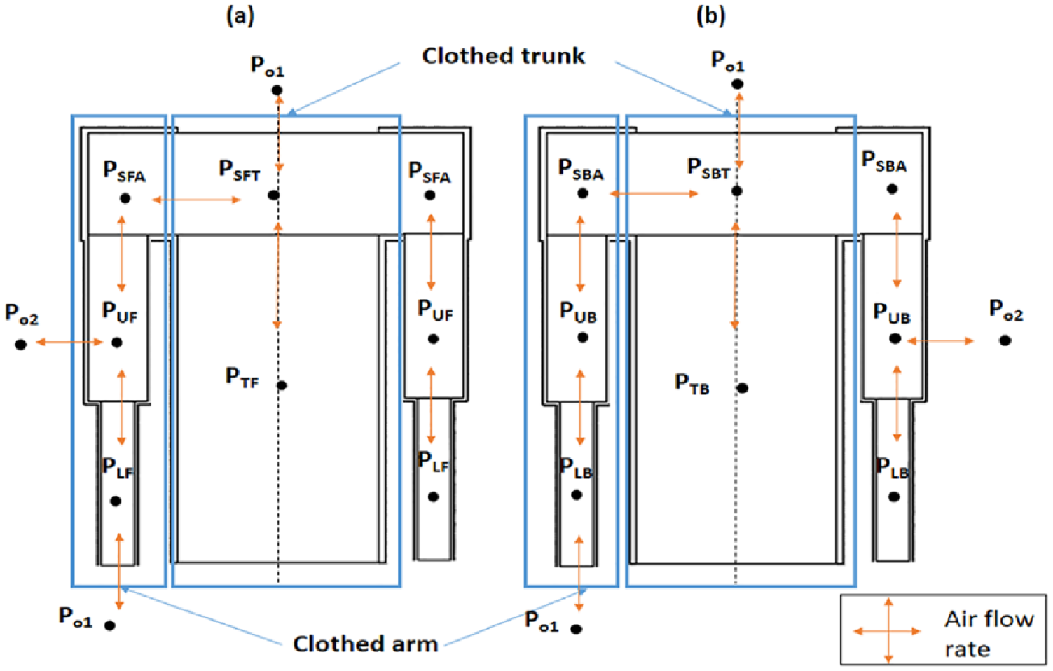
Nomenclature used in the model of the clothed upper part of the human body showing (a) the front side and (b) the back side.
The pressure differences in axial, angular, and radial direction trigger air to penetrate the fabric to the microclimate layer or out of it, move angularly or leave the microclimate in the axial direction. Hence, the ventilation model is a pressure-driven flow rate model. For instance, the axial difference in pressure between the microclimate air layer of the TF zone and the SFT zone δpt-x generates an axial flow rate going from the higher pressure node to the lower pressure node. On the other hand, the angular difference in pressure δPt-θ between the microclimate front and back air layer (TF zone and TB zone) generates an angular flow rate going from the highest to the lowest pressure node. Moreover, the radial pressure difference δPt-r between the microclimate air layer of the TF zone and the outside ambient side pressure node Po2 generates a radial flow rate through the fabric from the higher to the lower pressure node. Similarly, the other segmental zones experience the same air flow rates driven by the pressure differences at the various nodes. However, the clothed segments that have open aperture experience axial flow rate that depends on the pressure difference between the microclimate air layer node and the pressure at the opening Po1. The microclimate zones are the lower back and front zones of the arm (LB, LF), as well as the clothed portion of the arm connected to the shoulder in front and back sides, and the clothed portion of the trunk connected to the shoulder part in front and back sides (sfa, sft, sft, sbt). In this situation, some air could flow axially at the lower end opening of the clothed arm or at the top opening of the clothed trunk at the neck level. Note that Po1 is estimated from the pressure coefficient distribution around a solid cylinder while Po2 is estimated from the data of Fransson et al. 22 on the pressure coefficient distribution around a clothed circular cylinder representing the arm and the torso, respectively, with suction or blowing in radial direction.
Electric circuit analogy of the ventilation of standing upper human body part subject to external wind
In this section, the electric circuit analogy of the ventilation of the inter-connected human body part is developed for the case of standing human body subjected to external wind. For simplification, this section begins with the ventilation of basic clothed body segment (assumed independent) and then the model is extended to take into account the inter-connection between segments.
Basic clothed body segment ventilation model
The typical physical configuration for a clothed cylindrical segment is shown in Figure 1(b). By assuming Poiseuille flow model in the angular and axial direction, 21 and by integrating the angular and axial Navier–Stokes equations over the corresponding cross-section, the pressure difference equations are given by


where μ is the air viscosity; Ht, Yt, and rt are, respectively, the height, the air gap size, and the radius of the trunk.
The pressure difference ΔPt-θ and the flow rate Qt-θ have the same sign. The sign convention is positive when the flow is going from the front to the back side; thus, the pressure at the front side is greater than the pressure at the back side. Moreover, the air flow in the radial direction is through the permeable fabric covering the human body. The radial flow is penetrating or leaving though the fabric depending on the pressure difference between the outside and the microclimate air layer. Thus, the radial pressure difference is given by the following equation

On the other hand, given that the microclimate air layer is formulated as an incompressible fluid, the conservation of mass in the microclimate air layer of the clothed human torso is given by

Equations (3) and (4) are similar to the potential equation of the voltage difference across an electric resistance. Thus, there is an analogy between the air flow inside the microclimate air gap of the torso subjected to external wind on axial, angular, and radial directions and the resistance electric circuit.
Therefore, the electrical network representing the air flow inside the independent microclimate air layer of the clothed segment subject to external wind is shown in Figure 3. The presence of the switch S1 is basically related to the opening or closure of the cuff. When the cuff is tightly closed, no air flow rate is allowed to enter. In this case, the switch S1 is open. When the cuff is open, air enters from the aperture but it is resisted by the axial viscous resistance; thus, the switch S1 is closed in this case.

Figure of the analogy of the air flow inside the microclimate air layer of clothed segment subjected to external wind showing (a) physical representation of the ventilated clothed cylinder pressure nodes and (b) the analogous electric circuit.
Inter-segmental ventilation model of the standing upper clothed human body part
The presence of the connections between the clothed segments results in changing the pressure distribution in the microclimate air layer of each connected segment. For instance, the clothed arm and the clothed trunk are connected at the shoulder level inducing some air exchange at the connection. Therefore, different flow rates are generated in the connected arm and torso segments than those resulting from independent clothed segments. In the connected segment, the flow rate entering the clothed arm is different than the flow rate leaving it where the difference between the entering and leaving flow rates is basically the flow rate exchanged between the arm and the trunk. This exchanged air flow rate is defined as the inter-segmental ventilation.
Modeling the ventilation in physical configuration of the inter-connected clothed upper human body part (Figure 2) requires revising the segmental electric circuit of the independent segment. The driving force for the flow is not only restricted to the pressure difference between the outside and the microclimate air layer but also to the pressure difference between the connected segments. If we take the example of the lower arm zone (LF, LB), the inter-connection between the lower arm and the upper arm leads to a modification in the electric circuit as shown in Figure 4 where a resistance is added to the electric circuit for supplementary axial flow rate that passes from the lower arm to the upper microclimates in the front and back sides (LF-UF, LB-UB) or vice versa. The upper arms and the torso are connected to the shoulder zone on both front and back sides exchanging air flow rate. The upper arms and the torso are connected to the shoulder zone on both front and back sides exchanging air flow rate. The upper clothed arm is connected to the portion of the arm in the shoulder exchanging air with it (UF-SAF, UB-SAB) while the clothed torso is connected to portion of the trunk connected to the shoulder exchanging some air with it (TF-STF and TB-STB). These exchanges are represented by a resistance circuit between the upper arm and the shoulder pressures and between the torso and the shoulder (Figure 4). In addition, flow can enter through openings that are located either at the neck or at the cuff. Therefore, this flow is also resisted by the axial resistances Rx3 and Rx7 at the neck and the cuff, respectively.

Electric circuit analogy of the upper clothed human body part.
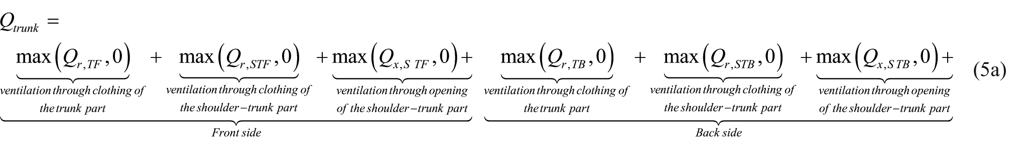
The ventilation of the clothed trunk is the sum of the entering conditioned outdoor air to the torso and to the trunk part connected to the shoulder at the front and back sides, as well as the conditioned outdoor air entering through opening. In case of non-walking conditions, the steady-state ventilation of the trunk is given by the following equation
The ventilation of the clothed arm is the sum of the entering conditioned outdoor air to the lower, upper and connected part of the shoulder. In case of non-walking condition, the steady-state ventilation of the arm is given by the following equation

where
The inter-segmental ventilation,


Electric circuit analogy of the ventilation of walking upper human body part subject to external wind
In the previous section, it was shown that exposing any clothed body segment to an external wind will lead to a pressure difference that allows air to penetrate or leave the microclimate layer leading to the ventilation of the clothed segment. When the human body is walking, the clothed arm is swinging which allows suction and blowing of air affecting the ventilation. Meanwhile, the clothed trunk does not swing while walking; but the relative velocity increases as following

where Vr is the relative pressure, and vw and vwalk are, respectively, the wind and walking velocities. Therefore, the ventilation model described for sedentary case could be applied for the walking condition by only replacing vw by Vr for the following non-swinging zones: TF, TB, STF, and STB. The remaining swinging zones associated with the clothed arm (LF, LB, UF, UB, SAF, and SAB) need to have a different ventilation model that takes into account the suction and blowing of air during walking.
Basic swinging clothed body segment ventilation model
The oscillating motion of the clothed arm is divided with respect to time into two phases. In the first phase shown in Figure 5(a), the human skin swings without touching the fabric forming an angle φ smaller than the angle at which contact occurs (φcontact). In Phase II, the human skin and fabric swing together to a maximum angle φmax. 18 Therefore, the average air gap size of the clothed arm in two phases estimated by integrating over the front side angle (–π/2 to π/2) and over the segment arm length Ha are given by
No-touch region (Phase I)

Touch region (Phase II)

Furthermore, the relative wind velocity of the oscillatory clothed arm is given by the following equation

The analogy between the flow of air inside the microclimate layer of the oscillating clothed arm and the electric circuit is based on the fact that when air is flowing inside the microclimate air layer, it is resisted by the viscous effect represented by an axial and angular resistance. On the other hand, the change in the flow of air due to the oscillating motion is represented by the axial and angular inductance. The air gap size of the oscillating clothed arm is assumed varying in sinusoidal manner with time during oscillation. The integration of the momentum over the corresponding cross-sectional area assuming the Wormesley parabolic profile in the y-direction leads to the pressure equations in axial, angular, and radial directions, respectively, as follows


where ΔPa-x, ΔPa-θ, and ΔPa-r are, respectively, the pressure drop in the axial, angular, and radial directions of the clothed arm; Qa-x, Qa-θ, and Qa-r are, respectively, the air flow rates in the axial, angular, and radial directions for the clothed arm; and α is the fabric air permeability expressed in m/s tested at a pressure drop ΔPm = 0.1245 kPa from standard tests on fabrics’ air permeability. 22 Equations (10a) and (10b) are similar to the voltage equation across a resistance and inductance in series, while equation (11) is simply similar to the voltage equation across a resistance.
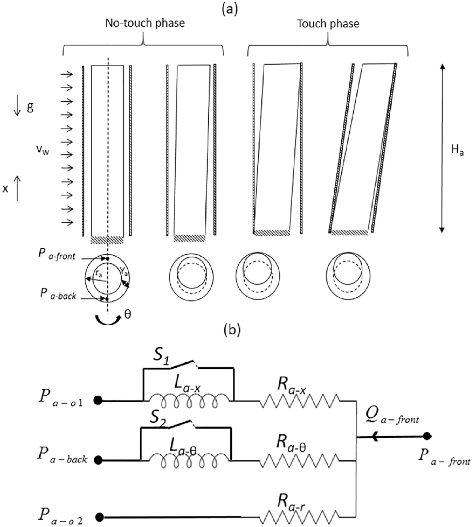
(a) The physical configuration of the clothed swinging arm and (b) the electric circuit analogy of the ventilation model.
Applying the conservation of mass, the variation of the volume inside the microclimate air layer raHadya/dt is then equal to the mass flow rates Qa-x, Qa-θ, and Qa-r in axial, angular, and radial directions, respectively, as follows

Equation (12) is similar to Kirchhoff’s first law that states the principle of conservation of electric current by declaring that the algebraic sum of currents in a network meeting at a point is zero. The back side of the clothed arm has the same momentum equations except that the decrease in volume is replaced by an increase in volume. In other words, if the air gap size increases at a time t on the front side of the clothed segment, the back air gap size will decrease by the same amount at the same time t.
Therefore, the electrical networks representing the air flow inside the microclimate air layer of the clothed segment subject to external wind and oscillating motion for an independent clothed arm is shown in Figure 5(b). Pa-o1 is the outside pressure estimated from the pressure coefficient distribution around a solid cylinder of the arm. The pressure Pa-o2 is estimated from the data of Fransson et al. 22 on the pressure coefficient distribution around a clothed circular cylinder representing the arm with suction or blowing in radial direction. Pa-front and Pa-back are the pressure in the front side and the back side of the arm, respectively; and Pt-front is the pressure in the front side of the torso. The switches S1 and S2 are closed so that the inductance does not have any role in the electric circuit when the inner cylinder representing the skin touches the clothing layer, and the two cylinders swing together and the air gap size becomes unchanged with time.
Although this model succeeds in predicting the segmental ventilation, the model needs to account for the effect of inter-segmental ventilation and hence the electric circuit of torso and upper arms will need to be modified.
Inter-segmental ventilation model of the walking upper clothed human body part
The swinging motion of the clothed arm in walking condition requires revising the segmental electric circuit of Figure 4. The upper clothed arm is connected to the portion of the arm in the shoulder exchanging air with it (UF-SAF, UB-SAB) while the clothed torso is connected to portion of the trunk connected to the shoulder exchanging some air with it (TF-STF and TB-STB). These exchanges are represented by a resistance-inductance circuit between the upper arm and the shoulder pressures and by a resistance circuit between the torso and the shoulder since the torso is not experiencing any oscillation.
Therefore, the electric circuit of the clothed upper human body of a walking human body is composed of the electric circuits characterizing each clothed segment connected between each other. The associated electric circuit is shown of the front side of clothed upper human body as shown in Figure 6. The back side has a similar circuit. All the resistances and inductances representing the ventilation used are summarized in Table 4 in Appendix 2. When the arm is oscillating during walking condition, the problem is steady-periodic and the segmental ventilation rate is obtained by integrating the penetrating mass flow rate given by equations (6) and (7) through clothing or through openings over one swing period T.

Electric circuit analogy of the upper clothed human body part under walking condition.
Numerical methodology
This section presents the numerical methodology used to solve the circuit equations. The input to the mathematical model included the geometrical parameters of each zone, the environmental conditions, the walking speed and swinging frequency and amplitude, and the clothing properties. The mathematical model is used to solve for the pressure nodes of each zone: PUF, PLF, PTF, PSAF, PSTF, PUB, PLV, PTV, PSAB, and PSTB. In case of inter-connected standing human body part, the system of 10 equations is solved to compute the 10 unknown nodal pressure values. In case of oscillating human body part, the equations are time dependent; therefore, iterations are used to find the nodal pressure values. At each instant t, an initial guess of all the pressure nodes was made and then the pressure values were adjusted in each iteration until a converged solution was reached at instant t such that overall mass were conserved in each grid and the values of pressure at the front and back sides converge to a minimum relative error of 10−5. At this level, the equations were re-solved for the next time step.
When all the pressure values are calculated, the flow rates are then estimated using the appropriate axial, angular, and radial flow rate equations of each zone as well as the ventilation and the inter-segmental ventilation according to the integrated equations (5) and (6).
Experimental methodology
The aim of the experiments was to measure the segmental ventilation and inter-segmental ventilation of the human body at different wind and walking conditions in order to validate the developed ventilation circuit model. The experiments were conducted on a thermal manikin by applying the tracer gas technique at different wind and walking conditions. Three settings of tracer gas injection were implemented into (1) both the clothed trunk and the arm simultaneously, (2) for the clothed trunk only, and (3) for the clothed arm only.
Thermal manikin
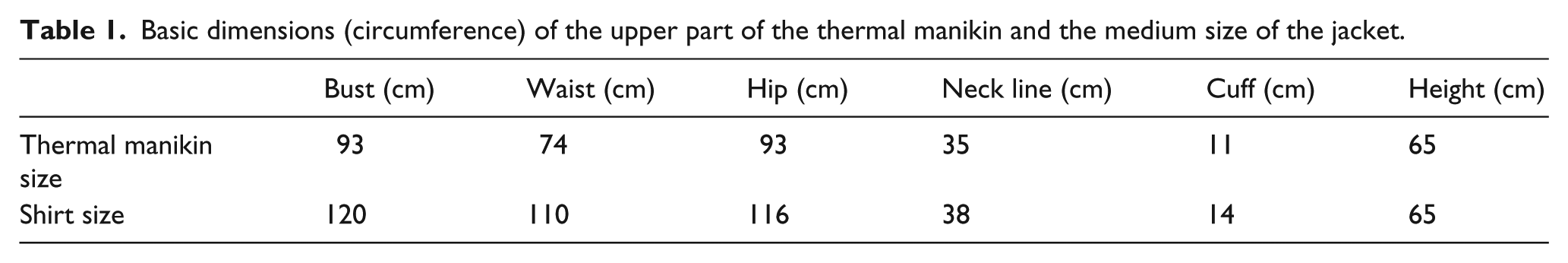
A 20-zone “Newton” thermal manikin (Measurement Technology Northwest, Seattle, Washington, USA) was used in the experiments. 23 The manikin is equipped with a walking mechanism. The manikin was dressed with a long sleeved cotton shirt and trousers having the dimensions illustrated in Table 1. The dimensions of the shirt were measured experimentally. The air permeability of the shirt was measured experimentally using the SDL MO2IA air permeability device with a standard deviation in repeated measurements of ±10−4 and accuracy of 0.1 l/(m2 s). 24 The shirt permeability was 1.38 ± 10−4 m/s.
Basic dimensions (circumference) of the upper part of the thermal manikin and the medium size of the jacket.
Two large fans with a diameter of 0.5 m were installed vertically on a stand with controllable wheels to adjust the distance between the manikin and the fans stand for the desired velocity at the front side of the manikin. An additional single fan is used whenever we want a torso relative velocity that is different than the clothed swinging arm. In fact, when considering the walking condition, the torso is moving in the real case scenario; however, the thermal manikin torso stays at the same place while the clothed arm is oscillating. The wind speed was measured by the manikin wind speed sensor which is an air velocity transducer (model 8475-06) at 3-min intervals at different locations and a mean value of wind speed is reported for each test scenario. The manikin and the fans were placed in a controlled environmental chamber. The chamber air temperature was measured by two manikin sensors at different heights (0.9 and 1.6 m) and the average was about 25°C ± 0.2°C. The relative humidity was measured at 1.6 m height and it was about 40% ± 3%.
Tracer gas method
The determination of local ventilation through upper human body part used tracer gas method.25–28 Argon was selected as tracer gas since it is non-explosive, non-toxic, and completely inert (no contamination of the tested product). Furthermore, argon is extremely rare in the atmosphere and will not contaminate and desensitize its own detector.
Figure 7 shows the schematic diagram of the experimental setup that estimated the ventilation based on the tracer gas method for local clothing ventilation and inter-segmental ventilation measurements. Furthermore, Figure 8 shows the experimental setup and the experimental components: the argon analyzer, the diaphragm pump, the flow controller, the argon tank, and the thermal manikin. An argon analyzer of 0.2% accuracy and a resolution of 0.01% was mounted in line at the outlet flow from the manikin microclimate air layer. A diaphragm pump (2–5 L/min) was installed to circulate the extracted air from the manikin microclimate. The flow of air was controlled and measured by an air flow controller (0–5 L/min). Another flow controller (0–1.5 L/min) was mounted at the top of the argon tank. The distribution and the sampling flow were provided using tubes sealed to the right arm (or left) and the half of the torso perforated with holes of 1 mm diameter as shown by the red/yellow holes in Figure 8(b). The inlet flow and outlet flow were controlled to 5 L/min while the added argon flows were 3 L/min. Taking advantage of symmetry, the distribution flow and the sampling flow were provided using tubes sealed to the right arm (or left), and half of the chest of the thermal manikin and perforated with holes of 1 mm diameter. The inter-connections between the clothed torso and sleeves were left open during the experiments.
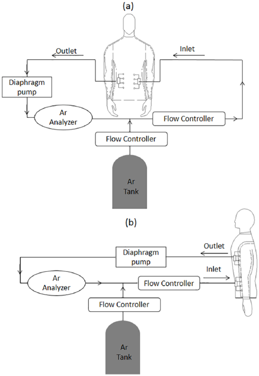
Schematic of the experimental setup to measure the ventilation of the front side for (a) the clothed trunk and (b) the clothed arm.

(a) The experimental setup, (b) the manikin shirt, (c) the walking thermal manikin, and (d) the argon tank with its flow controller.
Experimental protocol
In order to take into account the inter-segmental ventilation, the inter-connection between the clothed segments was opened. The experimental protocol for tracer gas method reported by Ismail et al. 20 was adopted in this work to determine segmental and inter-segmental ventilation.
The experiment was repeated until the steady state/steady periodic conditions of the recorded inlet and outlet concentrations of the argon gas were reached and recorded. The steady state/steady periodic condition was reached after 80–100 min. The circulated mass flow rate and the inlet and outlet concentration values are recorded. Their values are used to solve the ventilation rate and inter-segmental ventilation rate equations. Each experiment was repeated at least three times to ensure that the test variability is lower than 5%.
Six experiments were conducted for different combinations of wind speeds and walking as following: (0, 1.25), (1, 0), (1.2, 0), (0, 0.8), (1, 0.8), and (1.2, 1.25). For each given combination of wind speed and walking speed, three experiments were conducted with different argon gas injection schemes in order to find the clothing and inter-segmental ventilation. In the first experimental scheme, the argon gas was injected into both the clothed trunk and the arm simultaneously with one inter-connection and the steady/periodic argon gas concentration was measured in the arm and the trunk microclimates. In the second scheme, argon gas was injected in the clothed torso and the gas concentration was measured in the trunk microclimate. In the third injection scheme, argon is injected in the clothed arm and its concentration was measured in the clothed trunk microclimate. With the three injection schemes of argon, three mass balances can be derived to obtain the three sought ventilation rates: torso, arm, and inter-segmental.
Determination of segmental and inter-segmental ventilation
The experimental protocol and injection schemes of tracer gas were aligned with the definition of segmental and inter-segmental ventilation defined in equations (5) and (6). In the first injection scheme, the argon was simultaneously injected with the air flow entering the arm and the trunk microclimate air layers. The mass conservation of the tracer gas is given by the following equation
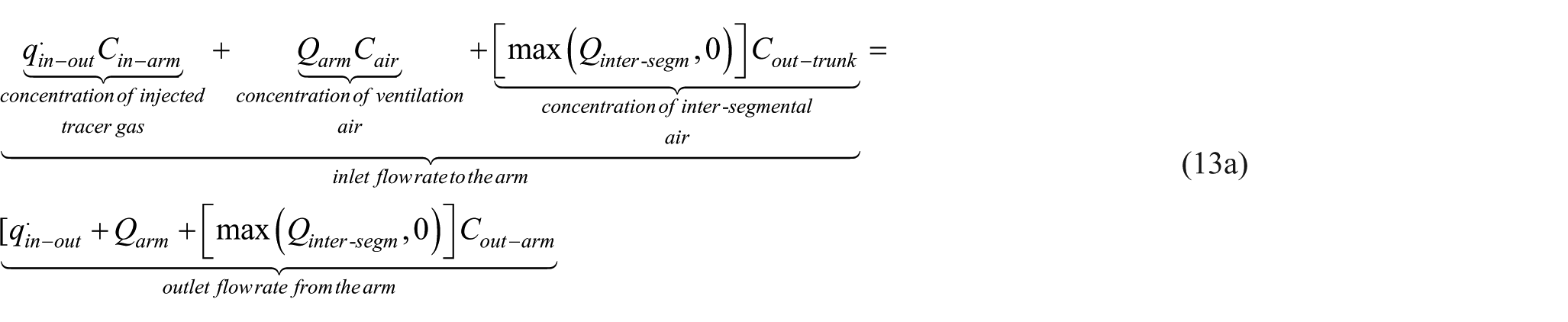
where
Similarly, the tracer gas equation for the trunk is given by

where
The second and third experiments add two additional equations derived from single segment injection experiments to solve for the three unknowns (Qtrunk, Qinter-segm, and Qarm) and to determine the inter-segmental ventilation direction (from arm to trunk or vice versa). The strategy of the second and third experiment is based on injecting the Ar to only one segment and tracking the Ar concentration on the other segment. If the Ar outlet concentration of the non-injected segment was greater than the atmospheric value, this proves that a certain mass flow rate of air is driven from the injected segment to the non-injected segment through the connection of the segments. If not, the inter-segmental ventilation could be either null or in the opposite direction.
Therefore, the equations derived for the single segment injection experiment depending on the direction of the flow are given as follows


where
Results and discussion
Model validation with experiment
In this section, the results of the developed model should be compared with the experimental results. The three injection scheme experiments were performed at three wind speeds (vw < 0.11 m/s, vw = 1 m/s, and vw = 1.2 m/s) and three walking speeds that included no walking (vwalk = 0 m/s); walking at 0.8 m/s corresponding to a DSPM (double steps per minute) of 38 and a frequency of about 50 r/min; and walking at 1.25 m/s corresponding to a DSPM of 60 and a frequency of about 80 r/min. Table 2 summarizes the obtained Argon concentrations for the different experiments. These values were used in estimating the segmental and inter-segmental ventilation rates Qinter-segm, Qtrunk, and Qarm.
Values of the experimentally measured argon concentrations in the various experimental conditions of wind and walking speeds.

The input parameters to the simplified ventilation circuit model are the clothing air permeability, the geometrical parameters of the clothed arm and trunk, the oscillation parameters for the arm, the walking speed for the trunk, and wind speeds. In the developed simplified model, the height, radius, and air gap of eight zones are presented in Table 3. The oscillating parameters depend on the walking speed at a typical angle of oscillation
The geometrical inputs of the air gap size, radius, and height of the eight zones.

Since the experiments allow the measurement of the argon concentration at the arm, and the trunk, the flow rates estimated experimentally are the segmental ventilation of the arm and trunk as well as the inter-segmental ventilation. Therefore, the experimental inter-segmental ventilation was compared to the predicted inter-segmental ventilation given by equations (13) and (14) while the experimental ventilation of the arm and the trunk were directly compared to the predicted ventilation rates given by equations (5a) and (5b).
Figure 9 shows the measured and predicted segmental ventilation rates at different conditions for (1) the clothed arm ventilation, (2) the clothed trunk ventilation, and (3) the inter-segmental ventilation. Good agreement was observed between the experimental and predicted ventilation rates with a maximum relative error of 16% and an average relative error of 13%. As mentioned in the tracer gas method description, the ventilation rates of the arm, the trunk, and the inter-segmental ventilation were estimated based on the argon gas concentration. The results show that the inter-segmental ventilation was flowing from the trunk to the arm. Furthermore, the inter-segmental ventilation increases with the increase in the relative wind speed and constitutes about 30% of the arm ventilation and 14% of the trunk ventilation. The maximum inter-segmental ventilation was obtained when walking in windy condition. This is because both wind and walking increase the relative speed. Increasing the relative speed leads to an increase in the pressure difference between the microclimate air layer and the environment. This phenomenon induces more air to penetrate through clothing and will lead to an increase in the segmental ventilation. Increasing the segmental ventilation will result, at its turn, in an increase in the inter-segmental ventilation. It is clear from Figure 9 that the developed model overpredicts the ventilation of the trunk but underpredicts the ventilation for clothed arm and inter-segmental ventilation. Indeed, the over-estimation of the trunk ventilation is mainly related to the shrinking of the air gap of the trunk clothing exposed to the fan. Consequently, the measured trunk ventilation is less than the predicted one. On the other hand, the opening of the arm drew the air flow into the microclimate and resulted in some swelling which increased the measured arm ventilation and affected the inter-segmental ventilation due to the increased pressure inside the arm microclimate.

Comparison between the measured and predicted ventilation rate of the (a) clothed arm, (b) clothed trunk, and (c) inter-segmental ventilation.
Finally, in order to show the importance of taking into account the inter-segmental ventilation, the pressure distribution (of relative pressure in Pa) were reported in Figure 10 for three different cases: (a) unconnected configuration at vw = 1.2 m/s, (b) connected configuration at vw = 1.2 m/s, and (c) connected configuration at vw = 1.2 m/s and vwalk = 0.8 m/s. The values are obtained from the mathematical model after being validated. It was shown that when the clothed segments are independent, the segmental ventilation of the trunk is less by 15% while the ventilation of the clothed arm is more by about 5%. This was observed by comparing the pressure at the arm and the trunk for the first two cases. When the connection was taken into account, the trunk pressure decreases at the front side from 217.8 to 125.6 Pa, allowing more air to penetrate through clothing since the air flow rate is going from the trunk to the arm. Meanwhile, the arm pressure increased at the front side from 361.5 to 361.7 Pa for the upper arm and from 361.62 to 361.8 Pa for the lower arm when inter-connection is incorporated decreasing the amount of penetrated air through clothing to the arm microclimate. This was due to the inter-segmental ventilation that allowed air to go from the trunk to the arm. This flow triggered more conditioned outdoor air to enter through clothing to the trunk microclimate resulting in an increase in trunk ventilation and decrease in arm ventilation. The same percentages were observed in the 3D study performed by Ismail et al.20,21 When the upper human body experiences some walking condition (at 0.8 m/s), the arm, trunk, and inter-segmental ventilation increases, this is shown by the increase in the air pressure difference between the microclimate air layers and the outside pressures.

Schematic showing the pressure distribution of the upper clothed human body part in case of (a) unconnected configuration at vw = 1.2 m/s, (b) connected configuration at vw = 1.2 m/s, and (c) connected configuration at vw = 1.2 m/s and vwalk = 0.8 m/s.
Model limitations and recommendations
The current model is used to track the penetrating air through clothing and opening apertures in order to accurately predict the segmental and inter-segmental ventilation which leads to accurate prediction of segmental heat losses of the upper human body. The model succeeded in predicting the segmental and inter-segmental ventilation for the common range of walking and wind speeds. Nevertheless, the simplicity associated with the electric circuit analogy has some limitations: the model is not sensitive for low air permeability and low relative wind.
Finally, the model simplicity does not take into account the deformation of fabric with the motion; this is because the model is based on a cylinder model (constant radius over the height). The simplicity associated with the validated developed model allows for an easy integration with any other model. For instance, the electric circuit model could be developed with a bio-heat model that predicts the thermal human response as well as the segmental heat losses given a certain activity level, environmental conditions, and clothing properties. 29
Conclusion
In this study, an electric circuit model for ventilation was developed of the upper clothed human body experiencing relative wind due to walking and external wind is developed. The model of air flow connects all the human body segments and estimates the inter-segmental ventilation between the segments for the clothed human upper part driven by difference of pressure in the microclimate air of the torso and the upper arms. The developed model is validated by conducting experiments on thermal manikin using tracer gas method. The tracer gas method provides the concentration of the inlet and outlet argon gas concentrations to estimate the segmental ventilation rates using the modified tracer gas equations that take into account the inter-segmental ventilation. Good agreement is shown between the experimental and the predicted data with a maximum relative error of 16%. The inter-segmental ventilation increases with the increase in the relative velocity constituting about 30% of the arm ventilation and 14% of the trunk ventilation.
Footnotes
Appendix 1
Appendix 2
Definition of the resistances and inductances in each direction.

| Direction | Symbol | Equation | Symbol | Equation |
|---|---|---|---|---|
| Axial | ||||
| Angular |
|
|
|
|
|
|
|
|
|
|
|
|
|
|
|
|
|
|
|
|
|
|
| Radial |
|
|
|
|
|
|
|
|
|
|
|
|
|
|
|
|
|
|
|
|
|
|
|
|
|
|
|
Declaration of conflicting interests
The author(s) declared no potential conflicts of interest with respect to the research, authorship, and/or publication of this article.
Funding
The author(s) disclosed receipt of the following financial support for the research, authorship, and/or publication of this article: We would like to acknowledge the financial support of the Lebanese National Council for Scientific Research for the project Award Number 103061-22909.