
Abstract
This study aims to use two unmanned vehicles (aerial vehicles and ground vehicles) to implement multi-machine cooperation to complete the assigned tasks quickly. Unmanned aerial/ground vehicles can call each other to send instant inquiry messages using the proposed cooperative communication protocol to hand over the tasks between them and execute efficient three-dimensional collaborative operations in time. This study has demonstrated integrating unmanned aerial/ground vehicles into a group through the control platform (i.e. App operation interface) that uses the Internet of Things. Therefore, pilots can make decisions and communicate through App for cooperative coordination, allowing a group of unmanned aerial/ground vehicles to complete the tasks flexibly. In addition, the payload attached to unmanned air/ground vehicles can carry out multipurpose monitoring that implements face recognition, gas detection, thermal imaging, and video recording. During the experiment of unmanned aerial vehicle, unmanned aerial vehicle will plan the flight path and record the movement trajectory with global positioning system when it is on duty. As a result, the accuracy of the planned flight path achieved 86.89% on average.
Keywords
Introduction
In recent years, the integration of air vehicles and ground vehicles is a technological development trend with impact. Using various vehicles to adapt to different environments to complete tasks, the results and performance of its execution exceed that of a single vehicle. 1 Many unmanned aerial vehicles (UAVs) are related products on the market, including general remote-control toys and airplane models. A base station controls the UAV-related products for a particular purpose, and when flying out to complete the assigned task, it will carry the necessary heavy tools. Unmanned ground vehicles (UGVs) are also quite mature. There are many types of tracked and wheeled vehicles, and even a two-wheeled self-propelled vehicle with an inertial measurement unit (IMU) can help balance the vehicle.
In addition, through a collaborative communication protocol between unmanned vehicles, 2 the manipulator of different vehicles can communicate with each other to discuss tasks, make decisions, or make requests for three-dimensional (3D) support when they are on duty. In such a way, the efficiency and flexibility of collaboration can be improved significantly. 3 This study aims to incorporate collaborative communication into unmanned vehicles and attach the payload, a multipurpose monitoring system, to each vehicle, as shown in Figure 1. People use a mobile phone App to monitor and control unmanned vehicles in real time through wireless network WiFi. When WiFi base stations have connected to a cloud platform, real-time monitoring and mobile control using App can significantly improve mission performance. The multipurpose monitoring system called iMonitor box includes micro cameras, infrared thermography, and gas sensor. 4 It can perform facial recognition and video recording, thermal imaging, and gas detection, respectively.

A group of UAVs/UGVs with multipurpose monitoring system.
In many cases, it is not easy to achieve the objectives of a task by relying on a single UAV or UGV. The task goals may change at any time or the restriction due to obstacles may occur occasionally. Therefore, an air-ground cooperative operation is needed to send a call to UAVs or UGVs. When performing individual tasks, the UGV can make a real-time support call to UAV and then UAV to take over the mission and carry out the task requested from UGV, and vice versa. Given a collaborative operation mechanism, the advantage of the UAV has a rapid response in the open air, and the edges of the UGV can shuttle in the building. This study proposed grouping 3D air-ground vehicles for increasing flexibility to have the task done effectively, and this approach is called iUAGV.
Related work
People used remote-control interfaces in an Android mobile phone to guide automatic cars. An in-vehicle camera has captured live video streams sent to a mobile phone via WiFi. 5 Meanwhile, s watched video streams on the phone through WiFi, and remotely control a car to achieve pulse width modulation (PWM) speed adjustment, off-road function, and monitoring environment function. 6 Furthermore, face recognition based on artificial intelligence (AI) has improved its performance significantly. 7 Using the libraries Python and OpenCV, face recognition can involve deep learning convolutional neural network (CNN) model and dynamic access control. 8 When the system recognizes a person’s face, a red square mark will appear around his or her head on the mobile phone panel to indicate the specified person.
Previous studies focused merely on monitoring environments and controlling the vehicles through a phone. This study integrates existing resources, including face recognition and infrared thermography, to make sure the vehicle can operate in the darkness. In addition, we also add several additional functions, such as taking pictures, filming, and detecting gas. The system will upload live videos to in-cloud storage for saving. The information about detected gases will display on a mobile phone panel to allow the user to understand the air quality at the moment. Therefore, a multipurpose monitoring system achieved the goal.
For years, the machine can collect temperature, humidity, and gas (e.g. CO, CH4, natural gas) to immediately show the environment’s status and save the information into the remote cloud storage. 9 Furthermore, s can operate a remote-control car and monitor the status of the environment with the App that implements gas detection, thermography, taking pictures, filming videos, and face recognition. People explored the automatic ground mapping and effective path planning in the cooperation system of UAVs and UGVs. 10 UAV used to take ground images in the air, and then image de-noised, image correction, and obstacle recognition to ground images can obtain a ground map. Image correction assisted UGV in improving the accuracy of obstacle recognition. According to the ground map, people proposed a hybrid path planning algorithm like a Genetic algorithm to optimize the planned route. Therefore, there is a challenge to cooperation between UAVs and UGVs well done for task exchanges or job collaboration between them. Cooperative communication is needed to implement the coordinated operation between UAVs and UGVs effectively when they are on duty at the same time and place. A group of unmanned vehicles equipped with sensing units can deploy on the air and ground to carry out environmental monitoring with a cooperative communication protocol.
Method
Integration of IoT, Cloud, and App
The current unmanned vehicle deployment study adopts the IoT concept (hereafter IoT) in the unmanned multipurpose monitoring system. Users can show videos or pictures taken by the micro-camera or images created by the thermography through the network of WiFi or 4G (Figure 2, arrows 3 and 5). 11

System architecture.
The system uses PhpMyadmin 12 in open-source software as a backstage calculating platform in the cloud system. 13 Users can control the self-balancing car with a cloud phone application. As s press the button in the phone application, the related index will be uploaded and stored in the cloud system. The vehicle will read and react to the received information. When s press the button, the vehicle gets and presents the latest uploaded news (Figure 2, arrow 1).
The videos or images taken by the vehicle on the App will be uploaded to the cloud system simultaneously, without occupying the built-in memory platform of the vehicle. In this way, the device can record videos for a whole day, and the cloud platform is used for mass storage to avoid insufficient capacity. In addition, four gas detectors are installed on the carrier, detecting up to 12 kinds of gases, such as PM2.5, CO2, LPG, CO, smoke, NH3, NO2, C3H8, C4H10, CH4, H2, and C2H5OH. As a result, people can update gas information to the cloud system, and s can instantly check the air quality on the App (Figure 2, arrows 2 and 4).
UGV with multipurpose monitoring
The multipurpose monitoring system, called iMonitor, acts as a payload to a ground vehicle, the two-wheeled self-balancing car, as shown in Figure 3(a). Although the place is sloped, the car can still balance itself while moving. When the car moves, the tilt angle and the speed are constantly measured to balance the wheels and decrease the vehicle’s tilt angle. According to Figure 3(b), hypothetically, if the car is being interfered with by the external force that generates the angular acceleration


Self-balancing car with the multipurpose monitoring system: (a) Self-balancing car. (b) Balance angle calculation.
Figure 3(a) is a structure of a multipurpose monitoring system. On the front, the system uses three lenses, and the leftmost is a gas detector lens. After statistical processing, the user obtains the surface temperature distribution of the object through the lens and generates an image. There are video streaming and face detection lenses in the middle, which can continuously do face tracking. When detecting a face successfully, the machine will automatically mark a red square line around it and record the video via the wireless network synchronizing App. Finally, the lens is used for recording and taking pictures. Due to the limitations of Raspberry Pi, the images captured by the lens do not play for video streaming at the same time. Therefore, we install another micro-camera. In multipurpose monitoring, iMonitor installed four gas detectors (MQ2, dust, CO2, and dangerous gas) on the system’s side. The information can be displayed on the App in real time to understand the environmental quality around the self-balancing car.
UAV with multipurpose monitoring
Figure 4 illustrates the structure of a UAV with multipurpose monitoring function. Figure 5(a) is the iMonitor’s payload. People can use UAVs to collect hazardous gas information during the flight in places with high risk and certain obstructions (natural disaster sites, chemical manufacturing, etc.). The collected data can be uploaded to the cloud platform so that s can read it immediately, as indicated in Figure 5(b). In addition, according to Figure 5(c), the UAVs can also monitor sensitive areas, use real-time images for face recognition, and determine the information of a person’s face. Furthermore, based on Figure 5(d), the thermal detector can find abnormal heat sources when monitoring or identify people with higher temperatures.

ZD550 UAV and its iMonitor payload.
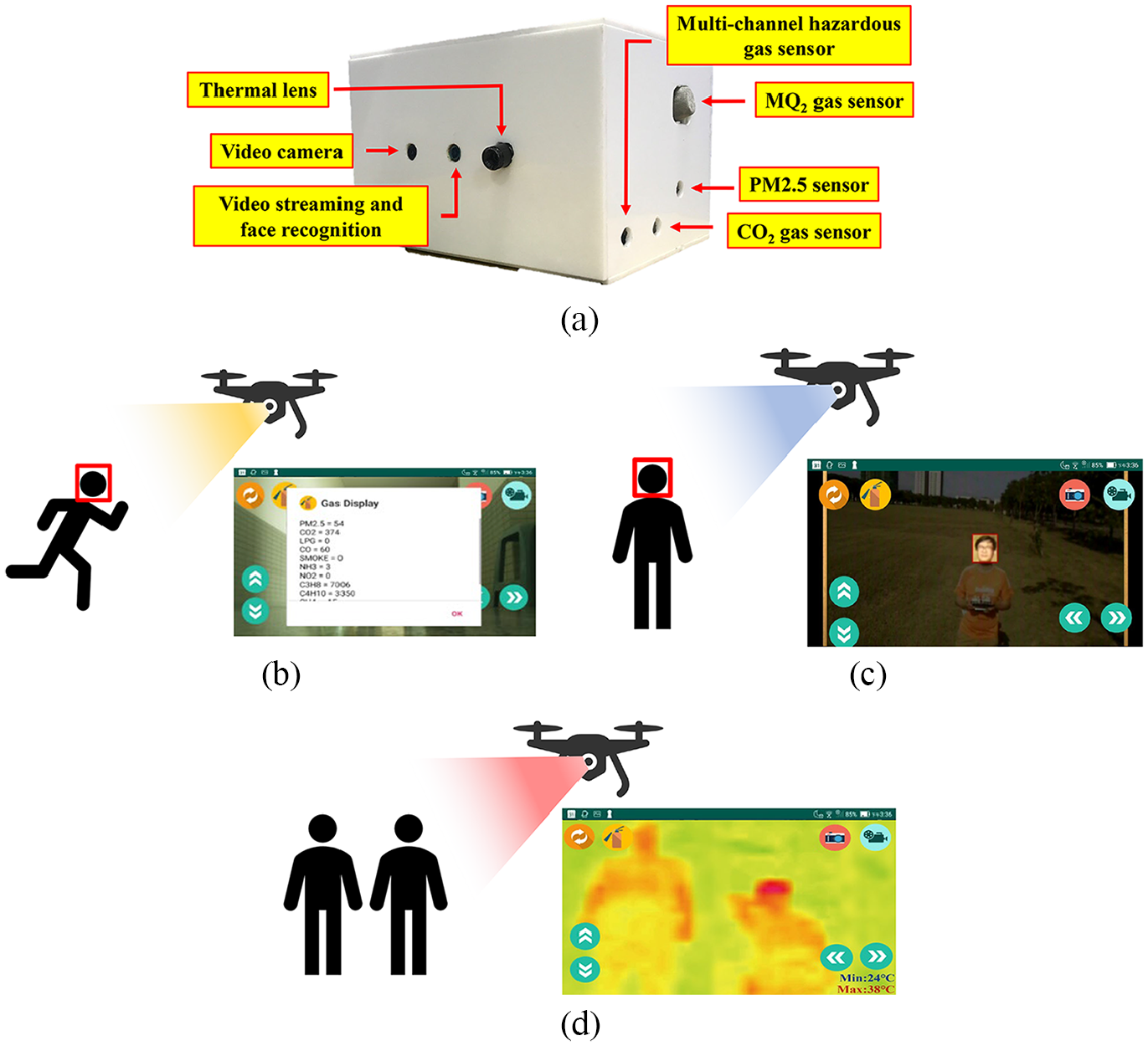
Applications of UAV: (a) iMonitor payload facility. (b) Mobile phone display hazardous gas detected from UAV. (c) Mobile phone display facial recognition detected from UAV. (d) Mobile phone display thermal sensing detected from UAV.
People also can use UAVs to replace high-risk situations, such as manual surveying or driving special land vehicles in the past. People used UAVs to measure and manage construction sites. UAVs with high-resolution cameras can capture various complex details. The details of the manual surveying and mapping can significantly reduce the errors of manual surveying. Meantime, UAVs can turn the traditional nontransparent construction process into a transparent process, and managers can obtain detailed construction sites by surveying and analyzing data at any time. In addition, UAV can help observe the cracks, deformation, and sleepers on the rail to apply to railway inspection, which makes the maintenance work safer.
Moreover, UAVs, 3D images, and modeling technology in geotechnical engineering can automatically check bridges, analyze connection problems, and evaluate the damage to facilities to decide whether subsequent maintenance is required. This technology can significantly decrease the labor cost of bridge maintenance and enhance efficiency and accuracy. Apart from assisting in surveying and mapping during the planning and construction of solar panel farms, people also used UAVs for real-time monitoring of the operation status of solar panel farms. UAVs equipped with gas imaging cameras captured the pictures that can send to the ground crew to identify damaged solar panels. UAVs can also monitor the invasive vegetation around the farm, dust on the panels, and other possible problems (such as the impact of strong winds causing the panels to skew or collapse).
Furthermore, gas imaging technology can detect overheated panels caused by the damage. In addition, UAVs can help engineers identify damaged turbines in the wind farm to ensure their regular operation. With the operation of the UAVs, the turbine blades can be quickly inspected in all directions for 2 to 4 times faster than traditional methods.
Furthermore, UAVs can locate the defective and damaged blades and provide HD pictures and cloud inspection reports. This method reduces the operation time and shutdown time for the traditional aerial and strengthens the efficiency of the wind farm. In agriculture, UAVs perform farmland surveying, mapping, spraying operations, sowing, and monitoring the health condition of trees.
Functions of iMonitor
A mobile App mainly controls the monitoring system of iMonitor. Figure 6(a) displays the starting screen of the system App. There are two main buttons, “Streaming” to view live streaming or gas imaging and “Folder” to view videos and images in the cloud system, as shown in Figure 6(b). When pressing the button “Pictures,” s can browse the photo files stored in the cloud system, as shown in Figure 6(c). In Figure 6(d), s press the button “Videos” to browse the videos as shown. Furthermore, s can use the two buttons below to select the login roles to correspond to the unmanned aerial/ground vehicles database.

App for multipurpose monitoring: (a) App start page. (b) In-cloud videos and images. (c) In-cloud photo archives. (d) In-cloud video files.
While pressing the button “Streaming” on the first screen, the user can see the images captured by the monitoring system. If detecting any face on the screen, the machine will first obtain the forehead temperature through an infrared gas lens, mark it with a red square, and show the personal ID and his or her forehead temperature as shown in Figure 7(a). If the person has not logged in to the system before, the system will mark him or her with a red warning and his or her forehead temperature, as shown in Figure 7(b). Regarding face recognition, 15 we use the library from the OpenCV image processing system and implement Python deep learning facial recognition program. The program has three parts: (1) face detection and data acquisition, (2) CNN model training, and (3) CNN facial recognition. Initially, s create a data set to store the registered face data. Since the facial recognition process compares and analyzes the captured image data and the existing image data, the user must first obtain face image data. We store each face ID along with a set of gray-scale face detection images. Each set of IDs is associated with around 30 captured image samples.
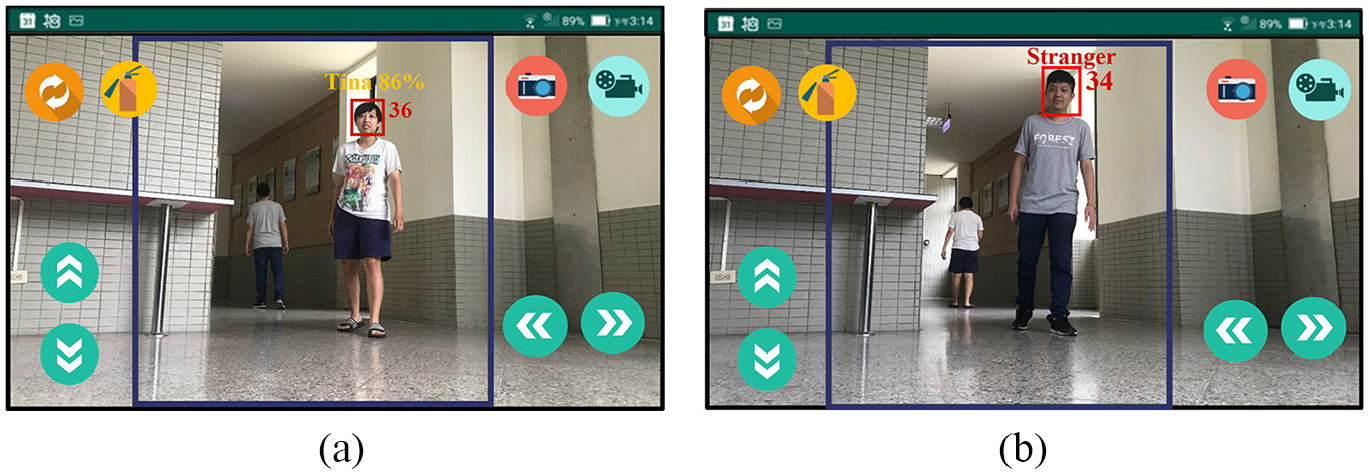
Video streaming: (a) Successfully detect the face and display the ID and forehead temperature. (b) The picture and forehead temperature of a stranger detected.
Users can also control UGV through the App remotely. There are four buttons for moving forward, backward, left, and right. Users need to press the button to make UGV move and release the button to make it stop. For example, when s press the red camera button in the upper right corner, the system will start taking pictures. In addition, when pressing the blue video record button in the upper right corner, the system will begin recording and showing a yellow pause button after that. Upon pressing this button again, s end the recording. The system will automatically upload the pictures to the cloud system without occupying any phone storage space.
Apart from the preset streaming images, s can also switch to the gas monitoring screen via the switch button in the upper left corner. People have used gas monitoring widely in the military, industrial, medical, and other fields, as shown in Figure 8(a). Finally, there is a “gas” button in the upper left corner, where s can instantly obtain the air quality and the gas concentration at the location, as shown in Figure 8(b). The system has four gas sensors to achieve multipurpose monitoring. 15 Real-time gas information can be displayed on the user’s mobile application to be aware of the environment quality around UAV/UGV. The sensing units, multichannel hazardous gas sensor, MQ2 gas sensor, CO2 gas sensor, and dust sensor can detect up to 12 various gaseous substances or particulate matter: PM2.5, CO2, LPG, CO, smoke, NH3, NO2, C3H8, C4H10, CH4, H2, and C2H5OH. Different sensors have other characteristics about sensitivity, resolution, and accuracy. With high sensitivity, four sensors can take various gas sensing independently without overlapping their responses.

Thermal and gas display on a mobile phone: (a) Thermal imaging display. (b) Gas concentration display.
Cooperative communication protocol for vehicles
Unmanned aerial/ground vehicles with a multipurpose monitoring system can operate through App and Server. The App has a communication board that allows UGVs and UAVs to communicate and facilitate coordinated operation. The communication board is available by clicking the cooperative communication button, as shown in Figure 9. The communication board displays frequently used functions so that s can enter a message and send it, as shown in Figure 10. The communication method between App and Server is to read the communication flags on the “Server” side. For instance, the UAVh/UGVh flags represent the online status of the unmanned aerial/ground vehicles, and the UAVm/UGVm flags represent the message sent by the unmanned aerial/ground vehicles. The UAVGPS/UGVGPS flags represent the GPS location information sent by the unmanned aerial/ground vehicles, and the “Call” flag represents callout.
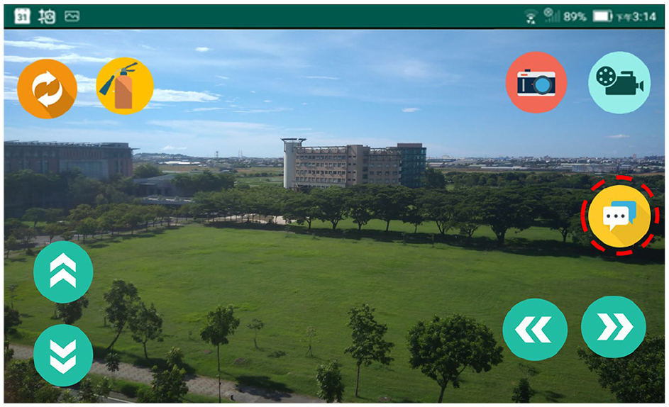
Cooperative communication button, marked by red dashed circle, on the App.
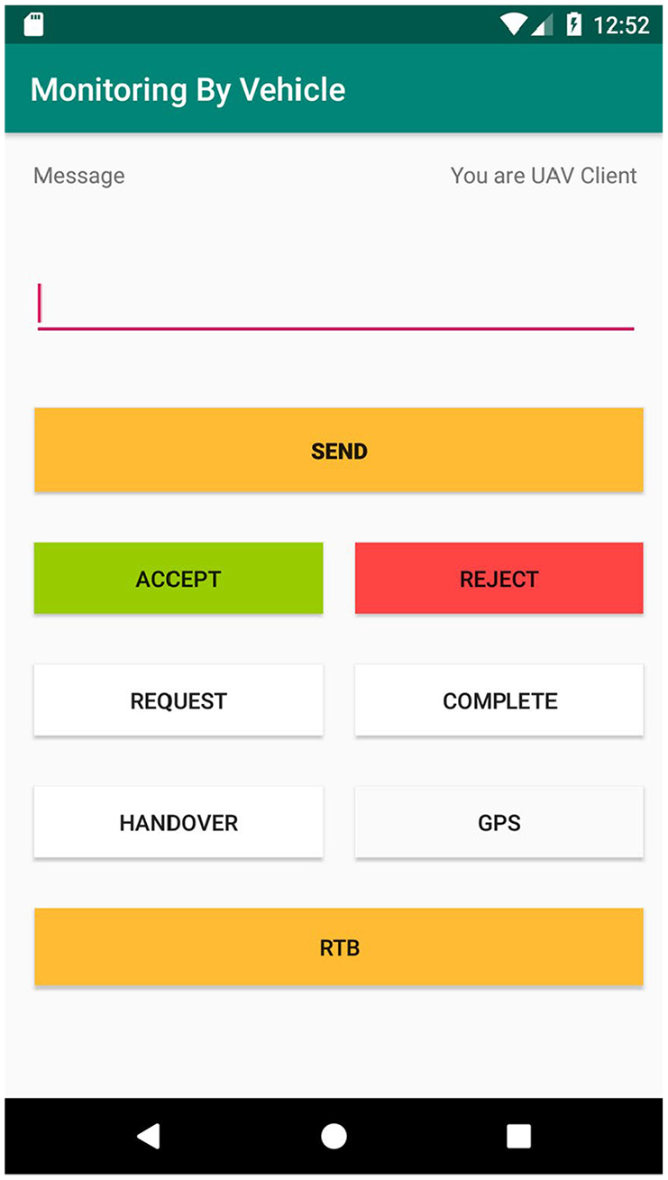
Cooperative communication page on the App.
Here presented five scenarios as follows to explain the communication process. The first scenario is Heart-Beat (wakeup page) that allows users to access the communication interface in UGV/UAV. The second scenario is a UGV paging a UAV and assigning tasks. The operation mechanism enables the task to execute more flexibly. Under urgent situations, the user can implement the alternative plan quickly to avoid the malfunction of the job. Third, a UAV pages a UGV and handing over the task to it, allowing suitable vehicles to operate in appropriate locations. Fourth, a UGV pages two UAVs to perform the tasks, followed by the fifth scenario, in which UAVs are calling two UGVs to perform tasks. The fourth and the fifth scenarios display the ability of multi-machine paging, execution, and communication.
Scenario 1: Heart-Beat wakeup notification
Each time users enter the communication interface, a user will send a Heart-Beat wakeup call to the others for notification, as shown in Figure 11. The procedures are as follows: (1) Send a Heart-Beat and a message of the device’s ID when the UAV enters the communication interface. Next, set UAV1h, where h represents heartbeat, as 1 to represent the active status of UAV1 and set UAV1m, where m stands for the message, as 1 to understand the message delivering at once. (2) The UGV1 receives the message. (3) The automatic response mechanism is activated. (4) Let others know that the message is received. (5) When the UGV1 initiates the communication interface, it sends a Heart-Beat and the device’s ID and sets UGV1h as 1 to represent the online status of UGV1. (6) UAV1 receives the message. (7) The automatic response mechanism is activated. (8) Let others know the message received and that they are in the communication interface and are ready to communicate. Conversely, if a UGV starts the communication interface in advance, it wakes up a UAV.

Heart-Beat wakeup call.
Scenario 2: UGV calls UAV to assign tasks
Scenario 2 refers to a UGV equipped with a multipurpose monitoring system at a particular place for environmental monitoring. However, the place is vast and blocked by a wall. To enter the place, the UAV needs to find the entrance and sends the information back to the UGV. If the UGV arrives, the entrance is collapsed and closed. Therefore, the UAV is assigned to complete some tasks. UGV can use the Callout function on the communication board to make a Heart-Beat wakeup call. The unmanned vehicle UGV1 calls the unmanned vehicle UAV1 at the vehicle’s location for the assigned tasks, as shown in Figure 12, to upload the GPS location of the unmanned aerial/ground vehicle to Server and to conduct regular communication through the flag set. The procedures are as follows: (1) Using the callout function, UGV sets the Call flag as 1, the UGV1GPS flag as 1, and sends GPS of UGV1Location. Meantime, UGV sends the task message “Find the entrance” and sets the UGV1m flag as 1. (2) The UAV reads the communication flag on the Server and checks whether there is any message. Since the UGV1GPS flag is 1, it reads the information of the UGV1Location and sets the UGV1m flag as 1. (3) After the UAV reads the message, it accepts the mission to the other group, sets the UAV1m flag as 1, and starts heading to UGV1 Location. After reaching the destination, it starts to look for the entrance. (4) UAV1m is reset as 0 after receiving the reply from the UGV. (5) After the UAV finds the entrance, it sends UAV1Location and sets the UAV1GPS flag as 1. (6) The UGV receives the UAV1 Location, moves toward the place, and finds the entrance collapsed and closed. (7) The UGV sends this message (not being able to enter) and assigns some UAVs to do outdoor monitoring. (8) The UAV receives the message. (9) The UAV accepts the task and starts flight over the wall to do outdoor monitoring. (10) The UGV resets the UAV1m flag to 0 after receiving the reply. (11) After going into the blocked place, the UAV reports the monitoring results. (12) After that, the UGV receives the results of the task. (13) The UGV sends the message “End of support,” sets the UGV1m flag as 1, and resets the Call flag as 0. (14) The UAV receives the message “End of support.” (15) UGV1m is reset to 0, and UAV sends the message “Return” to the UGV. UAV sets UAV1m as 1, and the UGV starts returning to Base. (16) The UGV resets UAV1m as 0, which completes Scenario 2: UGV calling UAV for task assignments.

A UGV assigns tasks to a UAV.
Scenario 3: UAV calls UGV to handover the task
In Scenario 3, a UAV equipped with a multipurpose monitoring system heads to a factory for environmental monitoring. After completing the external monitoring, the UGV is called at the indoor entrance since the system fails to enter the room. At present, the Heart-Beat wakeup call performs and illustrates the calling process between UAV1 and UGV2 to the UAV location and handing over the task, as shown in Figure 13, that is to upload the UAV GPS location to Server and communicate stably through the flag set. The procedures are as follows: (1) In performing the wakeup call function, UAV sets the Call flag as 1 and the UAV1GPS flag as 1, and then sends the UAV1Location. Once the message “Indoor Monitoring” has sent when handing over the task, UAV sets the UAV1m flag as 1. (2) Under the circumstance when the UAV1GPS flag is 1, and the UAV1m flag is 1, the UGV receives the message of UAV1 Location and reads the message of task handover. (3) Upon the message is successfully read, the UAV1m turns back to 0, sending the message to accept the task from the other group of people. Then, the vehicle starts heading to UAV1Location. UGV sets the UGV1m flag, here t, as 1. (4) The UAV terminal resets UGV1m to 0 after receiving the reply. (5) When the unmanned vehicle arrives at UAV1Location, it sends a message to start the tasks and sets the UGV1m flag as 1, which allows the vehicle to enter the room for monitoring. (6) The UAV receives the message. (7) It completes the handover task. The flag is set back to 0. Once UAV1 sent the message “Return,” UAV sets the UAV1m flag to 1. (8) UAV1m is set as 0, and here completed the handover task in Scenario 3 upon the UGV receives the message.

A UAV handover task to a UGV.
Scenario 4: UGV assigns tasks to multiple UAVs (Two UAVs used in this scenario.)
Scenario 4 refers to a UGV equipped with a multipurpose monitoring system. But we found that the place is empty, and multiple areas need to monitor. As a result, it is necessary to page two UAVs to complete the tasks faster. To complete the tasks, UGV can use the Callout function on the communication board. After the Heart-Beat wakeup call, the UGV1 calls two UAVs to head to the location of the unmanned vehicle for support. The communication process is shown in Figure 14, namely, to upload the GPS location of the UGV to Server and conduct regular communication with the flag set. The procedure is as follows. (1) Since UGV has activated the Call function, UGV sets the flag UGV1GPS flag as 1. UGV1 sent GPS location UGV1Location and the task message (monitoring Area 1) to UAV1 simultaneously. Furthermore, UGV1 sent the task message (monitoring Area 2) to UAV2. At this moment, UGV sets the UGV1m flag as 1. (2) The App on the UAV periodically reads the communication flag on Server to check whether there is a message. Given that the UGV1GPS flag is 1, the UAVs read the message regarding UGV1Location. As the UGV1m flag is 1, the mission message is marked as read. (3) After the two UAVs read the message successfully, they send the task message to the other party. UAV sets UAV1m and UAV2m flags as 1, and they start heading to UGV1Location. When the two UAVs arrive at the place, they start monitoring. (4) UAV1m and UAV2m are reset as 0 after receiving a reply from the UGV. (5) Two UAVs are responsible for monitoring their respective areas. After the completion of the tasks, UAVs report results to UGV. (6) The UGV receives the report of task results. (7) Then UAVs send the message “End of support.” At this moment, UGV sets the UGV1m flag as 1 and the Call flag as 0. (8) The two UAVs receive the message “End of support.” (9) UGV1m is reset as 0, and it replies to the UGV with the message “Return.” Moreover, UAV sets UAV1m and UAV2m as 1, starting to return to Base. (10) When the UGV receives the message, the vehicle resets UAV1m and UAV2m as 0. Finally, the process of UGV assigning the tasks to the two UAVs in Scenario 4 is completed.
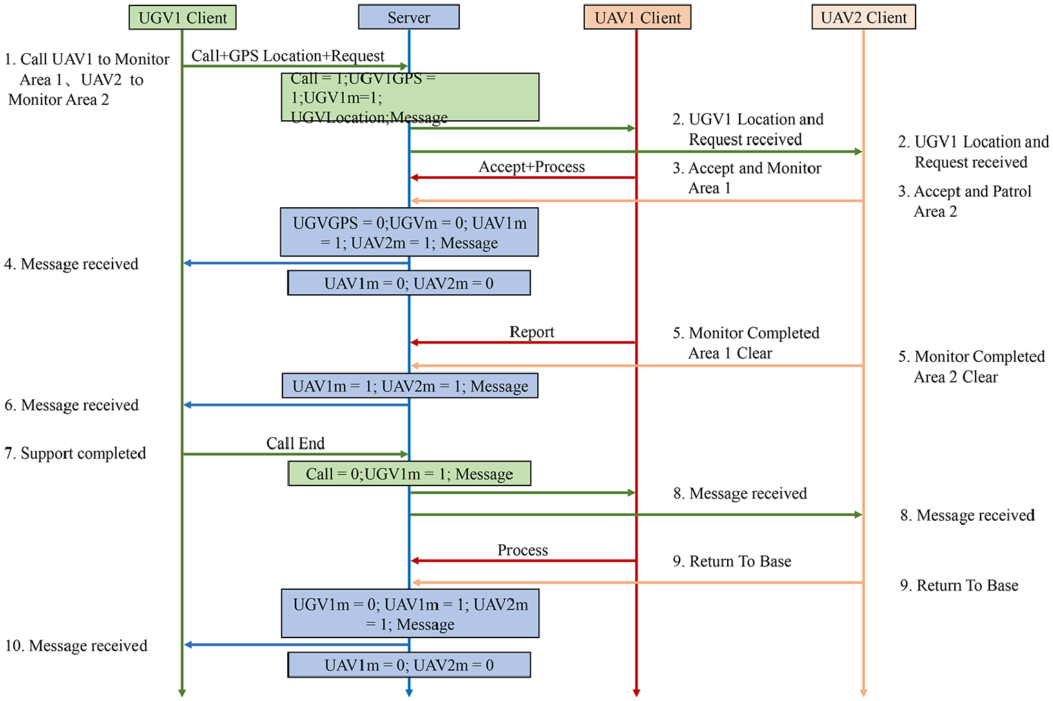
UGV assigns tasks to two UAVs.
Scenario 5: UAV assigns tasks to multiple UGVs (Two UGVs used in this scenario.)
In Scenario 5, a UAV equipped with a multipurpose monitoring system heads to a particular place to monitor, finding two warehouses in the area. Therefore, it is necessary to call two UGVs to complete the task more efficiently. UAV can use the Call function to make a Heart-Beat wakeup call. The UAV1 calls two UGVs, UGV1 and UGV2, to head to the location of the UAV for support. You can see the procedure of cooperative coordination between UGVs/UAVs, as shown in Figure 15. To be more specific, UAV needs to upload the GPS location of the UAV to the Server for communication through the flag set. The procedures are as follows: (1) In the Call function, UAV sets the Call flag as 1 and UAV1GPS flag as 1. UAV1 sends the GPS of UAV1Location to UGV1. The task message “Monitor Warehouse 1” is also sent to UGV1. In addition, UAV sends the message “Monitor Warehouse 2” to UGV2 as well. UAV sets the UAV1m flag as 1. (2) The App on the UGVs periodically reads the communication flag on Server to check whether there is any message. Because UAV sets the UAV1GPS flag as 1, UGV1 reads the message of UAV1Location. As the UAV1m flag is 1, UGV2 also reads the message. (3) After the two UGVs read the message, they send the message of accepting the mission to the other party, and UGV sets both UGV1m and UGV2m flag as 1. The UGVs head to UAV1Location, and start monitoring at the location. (4) When receiving a reply from the UAV, UAV resets UGV1m and UGV2m as 0. (5) Two UGVs are responsible for monitoring their respective areas. Upon completing the task and making a report, the UGV1m and UGV2m flags are set as 1. (6) After receiving the results, UAV resets the UGV1m and UGV2m flags as 0. (7) The message “End of support” is sent. At this moment, UAV sets the UAV1m flag as 1 and resets the Call flag as 0. (8) The two UGVs receive the message “End of support.” (9) UAV1m is reset as 0 to reply to the message “Return to Base.” Moreover, the UAV sets UGV1m as 1 to start returning to Base. (10) Finally, the UAV resets UGV1m and UGV2m as 0. Here completed Scenario 5 (UAV assignment with two UGVs).

UAV assigns tasks to two UGVs.
Performance evaluation of UAV planned flight path
During the experiment of UAV, UAV will plan the flight path and record the movement trajectory with GPS when it is on duty.
16
Here set the 4G base station as a checkpoint on the planned path and take a smooth curve between the two checkpoints as the best plan for the flight path. From takeoff to landing, the UAV will try to follow the checkpoint as much as possible and record the path deviation between the flight trajectory and the route of the planning checkpoint. The GPS positioning error of the 4G base station in the 10 m coverage area acts as the basis for judging the flight path deviation, that is, the distance between the flight trajectory and the planned path checkpoint. The performance evaluation is to calculate the accuracy of the flight path deviation. The accuracy of UAV flight path planning

Experiment results and evaluation
In the current experiment conducted on campus, a UGV serves indoor monitoring, including environment monitoring, face recognition, forehead temperature detection, filming, and pictures of people inside the building. In addition, UAVs perform outdoor monitoring, including gas monitoring, face recognition, forehead temperature detection, taking photos and videos of pedestrians. In open areas and indoor space, the cooperative operation between UGVs and UAVs has performed wakeup calls with the help according to the proposed protocol in this study, verifying a group of unmanned aerial/ground vehicles accomplishing multi-machine tasks.
Moving of unmanned vehicles
Moving of a self-balancing car
This system adopts a self-balancing car as a test vehicle, moving forward steadily even when encountering a slope. The mechanism of the self-balancing car has shown in Figure 16. For the motor, we use the TB6612FNG motor drive module to drive the GB37 DC deceleration motor. For balancing a car, the gyro (MPU6050) and the speed measuring engine (motor + Hall speed measuring compass) are used to obtain the car’s tilt angle and route distance. Then, the balanced output calculated by the mathematical formula (executed by Arduino development board) is used to control the wheels’ acceleration and eliminate the tilt angle of the car. To reach the balance during the movement of the balance trolley, 17 based on Figure 17(a) and (b), the balance trolley can maintain balance and move forward stably while passing through the bumpy slopes. The technical background of iMonitor 18 includes IoT, mobile applications, databases, face recognition, face tracking, gas detection, and infrared thermal imaging.
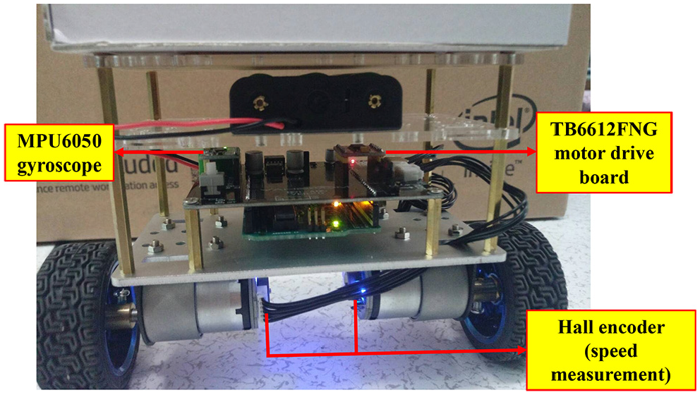
Unmanned mobile self-balancing car.

Test of moving of self-balancing car: (a) Traveling uphill. (b) Traveling downhill.
Flight of UAVs
This system adopts a UAV as a test vehicle, equipped with a carbon fiber frame with a diagonal wheelbase of 550 mm. A larger frame brings more stable flight. The frame uses a 4108 380KV motor to drive 14-inch carbon fiber blades, with a module mounted on the rack, as shown in Figure 18(a). The flight controller has a built-in barometer, gyroscope, and accelerometer, which can automatically correct the flight mode to avoid environmental interference and flight deviation. In addition, people used the flight controller with a GPS module for navigation and precise hovering. On-screen display (OSD) mode can pile the information from the flight controller onto images, allowing users to observe the parameters more intuitively. Thus, it is possible to use the iMonitor system more widely with the help of UAVs. In Figure 18(b), UAVs are efficient and flexible for gas monitoring, face tracking, and thermal detection in open areas.

UAV: (a) Anatomy of a UAV. (b) UAV flight test.
Operation of the monitoring system
Live streaming, taking pictures, and filming
When s intend to turn on streaming images, they can click the button “Streaming” on the App to watch the images through UGV or UAV, as shown in Figure 19(a) and (b). Furthermore, the system also provides functions for filming and taking pictures, as displayed in Figure 6(b)–(d). When s click the button “Camera” or “Video” on the App, the system automatically uploads the images to the cloud system without occupying phone storage space. Users can also click the button “Folder” on the App anytime to connect to the cloud system for images or videos to monitor the environment.

App live streaming: (a) UGV side. (b) UAV side.
Face recognition and measurement of forehead temperature
When the system detects a face successfully in the database, the machine will compare with the person who has registered and shows his or her ID with current forehead temperature. If the person has not registered before, it will display the word “stranger” and his or her current forehead temperature. According to the results of this experiment, this system can accurately mark the person and display his or her ID with forehead temperature when he or she is moving or standing still, as shown in Figure 20(a) and (b).

The system successfully recognized the image of the face: (a) UGV side. (b) UAV side.
Detection of air quality
This system has equipped with four gas detectors, which can detect 12 kinds of gases, including PM2.5, CO2, LPG, CO, smoke, NH3, NO2, C3H8, C4H10, CH4, H2, and C2H5OH. Moreover, the system can update the database on the App to inform s of the current air quality, as shown in Figure 21(a)–(d).

View in-cloud gas information: (a) App the first page from self-balancing car. (b) App the second page from self-balancing car. (c) App the first page from UAV. (d) App the second page from UAV.
Collaborative operations between unmanned vehicles
This experiment is to demonstrate the feasibility of cooperative operations between unmanned aerial/ground vehicles. Thus, this study has conducted four experiments according to four different scenarios. All the experiments have performed on a university campus. ZD550 acted as a UAV in charge of in-air missions. The self-balancing car served as a UGV to carry out the tasks either on open ground or within an indoor area.
UAV calling UGV
When performing a monitoring task on campus, a UAV may not lower its flight height because there are many trees or buildings. Therefore, it may be too large to enter indoor areas, so it is necessary to request support and assign a task to a UGV through the App, as shown in Figure 22(a). The UGV then arrives at the location and completes the task, as shown in Figure 22(b). Through sensing location and time, the experiment generated a trajectory tracking of a UAV diagram during the execution of the task to verify the trajectory of the UAV, as shown in Figure 23. The performance evaluation about flight path deviation and accuracy in UAV-calling-UGV scenario has listed in Table 1.

UAV calling UGV scenario: (a) UAV calling UGV. (b) UGV performs indoor tasks.
UAV trajectory tracking in UAV-calling-UGV scenario.
Path deviation and accuracy in UAV-calling-UGV scenario.

UAV: unmanned aerial vehicle; UGV: unmanned ground vehicle.
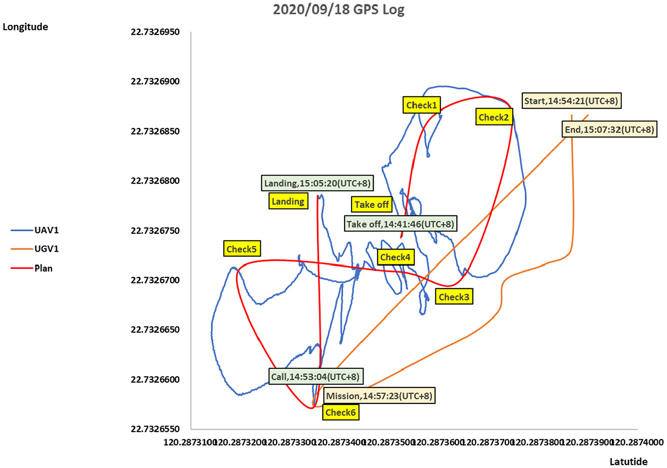
UGV calling UAV
In Figure 24(a), a UGV monitoring a campus may encounter a situation where the terrain is complicated or steps, making it difficult for the UGV to operate. Then, the UGV can request support from a UAV and assign a task to the UAV through the App, as shown in Figure 24(b). Then, through sensing location and time, the experiment of UAV-calling-UGV executed and generated a trajectory tracking of a UAV diagram during the execution of the task to verify the moving path of the UAV, as shown in Figure 25. The performance evaluation about flight path deviation and accuracy in UGV-calling-UAV scenario has been listed in Table 2.

UGV calling UAV scenario: (a) UGV calling UAV. (b) UAV performs outdoor tasks.

UAV trajectory tracking in UGV-calling-UAV scenario.
Path deviation and accuracy in UGV-calling-UAV scenario.
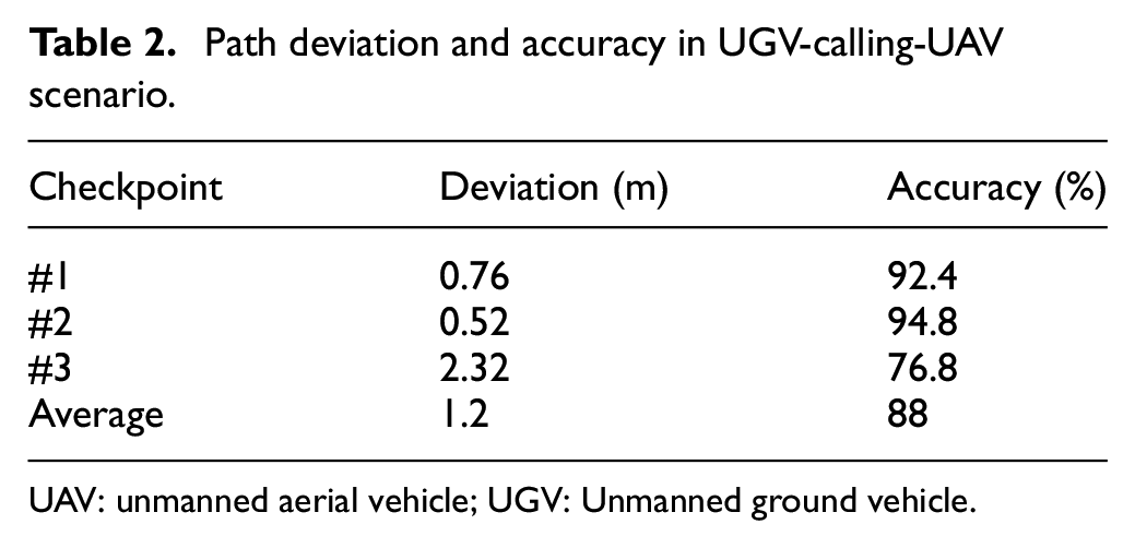
UAV: unmanned aerial vehicle; UGV: Unmanned ground vehicle.
UAV calling two UGVs
When monitoring a campus, a UAV may encounter large buildings or gymnasiums. As shown in Figure 26(a), two UGVs are requested for support through the App to help take people’s forehead temperatures in the building to complete tasks efficiently. The two UGVs arrive at the designated location to complete the task, as shown in Figure 26(b). Through sensing location and time, the experiment generated a trajectory tracking of a UAV diagram during the execution of the task to verify its flight path, as shown in Figure 27. The performance evaluation about flight path deviation and accuracy in UAV-calling-two-UGVs scenario has been listed in Table 3.
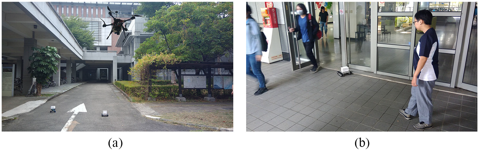
A UAV calling two UGVs scenario: (a) UAV calling two UGVs. (b) Two UGVs perform indoor tasks.

UAV trajectory tracking in UAV-calling-two-UGVs scenario.
Path deviation and accuracy in UAV-calling-two-UGVs scenario.

UAV: unmanned aerial vehicle; UGV: unmanned ground vehicle.
UGV calling two UAVs
While monitoring a campus, a UAV receives a support request from other buildings and sends requests for support to two UAVs, as illustrated in Figure 28(a). Soon afterward, the two UAVs arrive at the designated location to perform the task, as shown in Figure 28(b). Through sensing location and time, the experiment generated a trajectory tracking diagram of each UAV during the execution of the task to verify its flight path, as shown in Figure 29. The performance evaluation about flight path deviation and accuracy in UGV-calling-two-UAVs scenario has been listed in Table 4.
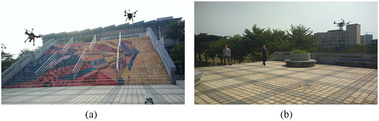
A UGV calling two UAVs scenario: (a) UGV calling two UAVs. (b) Two UAVs perform outdoor tasks.

UAV trajectory tracking in UGV-calling-two-UAVs scenario.
Path deviation and accuracy in UAV-calling-two-UGVs scenario.
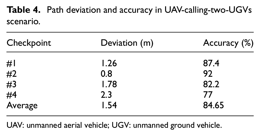
UAV: unmanned aerial vehicle; UGV: unmanned ground vehicle.
Discussion
This study focuses on the multi-machine cooperation of unmanned aerial/ground vehicles with artificial remote control. In the experiments, the mobile phone App acts as a coordinator to send/receive messages between UAV and UGV through a cooperative communication protocol. The user used the UAV remote controller artificially to operate the UAV flight. In contrast, the mobile phone App only remotely worked the moving of UGV. The user piloted the UAV directly using remote controller, and thus human being vision realized obstacle avoidance during the UAV flight. Although there is a planned flight path, errors in the movement process caused by human manipulation will cause the recorded trajectory to be unsmooth when flying to various checkpoints on the planned flight path. Unsmooth trajectories represent excess movement distance and energy consumption, which will harm UAVs’ endurance and mission sustainability. In the future, the improvement will be toward self-driving vehicles’ direction because they will respond more quickly and intuitively than human operations when performing tasks. As a result, it will be able to do more complex operations after exerting autonomy.
Conclusion
This article proposes the air/ground cooperative communication protocol for UAV and UGV deployed in a group. As a result, the proposed iUAGV can carry out high-efficiency 3D collaborative work and complete the assigned tasks as quickly as possible in the shortest time, the smallest space, and the best adaptation in the environment. Furthermore, this study has demonstrated integrating unmanned aerial/ground vehicles into a group through the control platform (i.e. App operation interface) that uses the Internet of Things. Thus, a wider group of unmanned vehicles can communicate through the proposed air/ground cooperative communication protocol. Furthermore, the payload iMonitor can perform various monitoring functions in real time successfully. In terms of improvement, it hopes that the UAV has the self-driving ability to avoid obstacles by itself, and at the same time do obstacle avoidance path planning for UGV on the ground, which we believe to be of great help to UGV.
Footnotes
Handling Editor: Dr Yanjiao Chen
Author contributions
B.R.C. and J.-L.L. conceived and designed the experiments; H.-F.T. collected the experimental data set and C.-F.H. proofread the article; B.R.C. wrote the article.
Declaration of conflicting interests
The author(s) declared no potential conflicts of interest with respect to the research, authorship, and/or publication of this article.
Funding
The author(s) disclosed receipt of the following financial support for the research, authorship, and/or publication of this article: This article is supported and granted by the Ministry of Science and Technology, Taiwan (MOST 110-2622-E-390-001 and MOST 109-2622-E-390-002-CC3).