
Abstract
The thermal bow of the rotor occurs in the cooling process after the shutdown of the aeroengine. The deflection of the bowed rotor is the primary concern of the research on this problem. The objective of this work is to propose a method to predict the bow shape of the rotor with the measured temperature and displacement in a rotor thermal bow experiment. The experiment was introduced and the variations of the measured temperature and displacement were analyzed. A series of polynomial function was proposed to model the bowed shape of the rotor. The measured temperature and displacement were taken into considered in the constraint equations, with which the coefficients in the polynomial function were obtained. The bow shapes of the rotor at different time in the experiments were analyzed. Results showed that the maximum deflection of the rotor was much greater than the measured displacement at the sections near the rotor support. The forced cooling could reduce the thermal deflection of the rotor quickly. The analysis of the different cases of experiment indicated that the proposed method could predict the bow shape of the rotor with the measured temperature and displacement.
Introduction
The natural convection in the cooling process of the aeroengine generates a vertical temperature gradient on the rotor, which leads to the thermal bow of the rotor. The eccentricity results from the thermal bow generally causes high vibration of the rotor,1,2 even rub between the rotor and the stator during the restart of the aeroengine. 3 The shape of the bowed rotor, with which the dynamics of the rotor could be analyzed,1,4 is the primary concern in the research on the thermal bow problem. With the fluid-thermal-mechanical coupled method, it is convenient to obtain the detailed thermal bow of the rotor by numerical simulations 5 . As it is difficult to measure the displacement in high temperature environment, only few displacement measurements and a number of temperature measurements are generally recorded in the experimental research works. The detailed shape of the thermal bow has not been predicted by any experiment yet. The objective of this work is to propose a method to predict the detailed shape of the rotor thermal bow based on the measured displacement and temperature results.
The rotor thermal bow in aeroengine is a complex fluid-thermal-mechanical coupled problem. The numerical simulation is widely applied to unveil the mechanism of the rotor thermal bow of aeroengine. With the commercial packages, it is convenient to investigate the effects of the rotor geometry,6,7 the case and the integration design,6,8 the blades and vanes, 9 and the operation of the aeroengine before shutdown, 10 on the rotor thermal bow by numerical simulation. Numerical simulation is an effective method to study the thermal bow of aeroengine qualitatively, while the quantitative research on this problem still requires experimental test. Recently, several experimental research works of the rotor thermal bow have been published. In order to measure the natural convective heat transfer coefficient in the thermal bow process, Fahy et al. 11 put emphasis on the transient temperature of the model rotor, and the displacement was not recorded in the experiment. Smith et al.12,13 conducted a progressive experimental research on the thermal bow of rotor. At the initial stage, the thermocouple and the linear variable displacement transducer were applied to record the temperature and the displacement of the rotor, respectively. 12 In the improved experiment, the thermographic infrared camera was used to measure the temperature, while the laser sensor was adopted to record the deflection of the rotor. The temperature measurements generally matched well with the simulations, while the thermal deformation of the rotor support and the uniformity of the rotor initial temperature will cause obvious difference of the displacement measurement with the numerical simulations. 13 Moreover, only the displacement at the axial center was recorded, and the detailed bow shape of the rotor could not be observed in the experiments. Based on the beam theory and the thermal mechanical principle, Zhuo et al. 14 proposed an analytical method to predict the thermal bow shape of the rotor in a heavy duty gas turbine. The assumptions of the constant temperature gradient on the segment of the rotor limited the application of the analytical method in aeroengines, in which there was great temperature gradient in the axial direction. It can be seen that a general method to predict the detailed thermal bow shape of the aeroengine rotor with the measured temperature and displacement is still missing.
The objective of this work is to predict the detailed bow shape of the rotor, and an integration method of the temperature and displacement measurements in the experiment is to be proposed. The transient bow shape of the rotor in the experiment will be investigated. The experiment is introduced in section “The experiment of the rotor thermal bow,” and the integration method will be proposed in section “Predicting the bow shape of the rotor with the measured displacement and temperature.” The analysis of the transient thermal bow of the rotor will be given in section “Results and discussion,” and finally, the conclusion of this work is given in section “Conclusion”.
The experiment of the rotor thermal bow
An experiment has been conducted to investigate the problem of rotor thermal bow. The test rig included a model rotor, two elastic supports, and a cylinder heater, as illustrated in Figure 1(a). The model rotor was composed of a model compressor rotor and a model turbine rotor, as depicted in Figure 1(b). The model rotor was designed to have similar configuration and dynamical behavior of a gas turbine high pressure rotor. The total length of the model rotor was 1800 mm. The model turbine disk had the maximum diameter as 370 mm and the thickness as 40 mm. The maximum diameter of the drum in model compressor rotor was 166 mm, and the thickness of this drum is 10 mm. The cylinder heater could provide a temperature environment with vertical temperature gradient for the rotor, as shown in Figure 1(c).

The test rig of the rotor thermal bow: (a) illustration of the test rig, (b) picture of the test model rotor, and (c) picture of the assembly of the experiment.
Generally, the thermal bow of rotor occurs during the cooling process in practical engineering. While the cooling process generally takes more than 1 h, it will lead to much experimental time and huge amount of data in the experiment. Since the direct cause of the rotor bow is the vertical temperature difference at the rotor sections, the same bow shape of the rotor will be occurred in the heating process for the same vertical temperature difference at the rotor sections. As a result, the thermal bow of the rotor was measured in the heating process in this study.
Instrumentation
Six sections of the model rotor were recorded in the experiment, denoted as S1–S6 in Figure 2(a).

The instrumentation of the experiment: (a) illustration of the locations of the displacement and temperature measurements, (b) picture of the displacement measurement, and (c) picture of the thermocouple.
In the hot environment within the cylinder heater, only the temperature on the model rotor was measured in the experiment. During the experiment, the rotor had a spatial temperature distribution. The temperature measurement on the rotor should take the following two aspects into consideration. The first was that the temperature measurement sections should be evenly located in the axial location. As shown in Figure 2, the experiment rotor included disks and drums. The heavy disks would lead to much delay of the temperature measurement, and the drums were selected to place the temperature measurements. With the limitations of the space within the heating cylinder and the data recorder, four sections of temperature measurements were selected (S2, S3, S4, and S5 in Figure 2). As illustrated in Figure 2(a), eight K-type thermocouples were placed at four sections (S2, S3, S4, and S5), with each section having two temperature measurements at the top and the bottom. The temperature at the top and the bottom of each section of the rotor could be recorded directly by the thermocouples.
As the temperature was relative low outside the cylinder heater, four eddy current sensors were placed at the two end sections of the model rotor (shown as S1 and S6 in Figure 2(a)). As illustrated in Figure 2(a), two eddy current displacement sensors were placed vertically above and below the rotor, respectively, to get rid of the influence of the rotor radial expansion on the displacement measurement. The lateral displacement

Here,
The picture of the placement of the eddy current displacement sensors at one of the sections in the experiment is shown in Figure 2(b).
The experimental tests
The procedure of the experiment was as follows: (1) set the target temperature of the cylinder heater and turned on the power of the cylinder heater. The heating time started counting. The temperature of the cylinder heater rises and the model rotor was to be heated from the ambient temperature. (2) The cylinder heater reached the target temperature and kept as the target temperature. The model was kept heating to the end of the heating time. (3) The power of the cylinder heater was turned off at the end heating time. (4) The model rotor was to be cooled naturally or by blowing of air. The temperature and the displacement sensors were recording corresponding data during the experiment.
In order to study the heating temperature on the thermal bow of the rotor, three tests were conducted with the target heating temperature of the cylinder heater setting as 200, 250, and 300°C, respectively. In addition to the natural cooling process, the experiment of the forced cooling with blow air was conducted as well. The cases of the experimental tests are listed in Table 1.
The cases of the experimental tests.

The experimental results
During each case of the experimental test of the rotor thermal bow, the temperature and the displacements of the measured sections could be obtained. As the variations of the temperature and the displacement with time for different cases were similar, only the cases of 250°C heating with natural cooling and 250°C heating with forced cooling were to be given.
Results of the 250°C heating with natural cooling
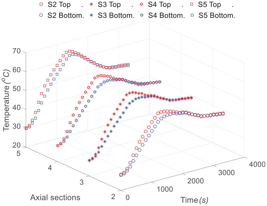
The variations of the measured temperature of the sections S2, S3, S4, and S5 with time are plotted in Figure 3. It could be seen that the temperature increased with the heating time. After the cylinder heater was powered off, the temperature gradually reached the maximum value and then decreased with time. At each section, the temperature at the top of the section was greater than the temperature of the bottom of the section.

The variations of the measured temperature with time in the case of 250°C heating with natural cooling at the sections S2, S3, S4, and S5.
As the sections S2, S3, S4, and S5 were located at different axial positions in the hot environment, the temperature of the sections was different. The maximum temperature of the section S5 was the greatest among the measured sections.
Compared to the temperature value at the sections, the temperature differences between the top and the bottom of the sections were more important to the study of the thermal bow of the rotor. With the measured temperature at each section, it was convenient to obtain the difference of each section, as plotted in Figure 4. During the experiments under different heating temperatures, the variations of the temperature differences with time were similar. The temperature difference at each section increased with the heating time and gradually decreased after the power of the heater was turned off. Due to the difference of the geometry of each section, the temperature differences of the sections were different. The S2, S3, S4, and S5 had the maximum temperature difference as 4.6, 6.9, 7.6, and 5.3°C. There was a great slope of the reduction in the temperature difference after the shutdown of the heater, while the slope of the reduction gradually decreased. At about 3000 s, the temperature differences of the sections decreased to about 1°C.

The differences of the temperature of the top and the bottom of the measured sections in the case of 250°C heating with natural cooling: (a) the section S2, (b) the section S3, (c) the section S4, and (d) the section S5.
The lateral displacements at the sections S1 and S6 could be obtained by equation (1) with the eddy current displacement sensors at the two sections. As plotted in Figure 5, the displacements of the sections S1 and S6 were compared. It could be seen that the lateral displacements at the two sections increased with heating time and gradually decreased after the power of the heater was turned off. The section S6 had greater displacement than the section S1. The maximum lateral displacement of the section S6 was about 0.02 mm.

The measured bow displacements at the sections S1 and S6 in the case of 250°C heating with natural cooling.
Results of the 250°C heating with forced cooling
The results of the case of the 250°C heating with forced cooling could be obtained and plotted. The temperatures of the measurements at the sections S2, S3, S4, and S5 are plotted in Figure 6. The variation of the temperature in this case was similar to the natural cooling case in the heating time of the experiment. The difference between the natural cooling case and the forced cooling case occurred after the start of the forced cooling, which was proceeded just after the shutdown of the cylinder heater. As shown in Figure 6, the reduction in the temperature of each section was more obvious than the natural cooling case. The effect of the forced cooling on the temperature of the model rotor could be seen by the temperature difference at the sections as well.
The variations of the measured temperature with time in the case of 250°C heating with forced cooling at the sections S2, S3, S4, and S5.
The temperature difference at the sections could be obtained, as plotted in Figure 7. The maximum temperature differences at the sections S2, S3, S4, and S5 were 4.7, 6.9, 7.5, and 5.4°C, respectively. As the maximum temperature difference of each section happened at the end of the heating time, the forced cooling has little effect on them. However, in case the forced cooling began, the variations of the vertical temperature difference with time were more shaper than the natural cooling case. As the blowing of the ambient air, the rotor was cooled more quickly than the natural case, and the vertical temperature differences reduced shapely with time.

The differences of the temperature of the top and the bottom of the measured sections in the case of 250°C heating with forced cooling: (a) the section S1, (b) the section S2, (c) the section S3, and (d) the section S4.
The lateral displacements at the sections S1 and S6 in the 250°C heating with forced cooling are compared in Figure 8. The overall variations of the displacements with time were similar to that in the natural cooling case. Different from the previous case, the reduction in the lateral displacements at the two sections was more apparent than the natural cooling case. This was resulted from the sharp reduction in the vertical temperature difference in the forced cooling case.

The measured bow displacements at the sections S1 and S6 in the case of 250°C heating with forced cooling.
Predicting the bow shape of the rotor with the measured displacement and temperature
In order to release the assumption of the constant temperature gradient in the segment of the rotor in Zhuo et al., 14 the polynomial function was applied to model the bow shape of the rotor. The general form of the polynomial function was

Here,
The constraint equations
As shown in Figure 9, the measured displacement and temperature in the experiments should be satisfied by the function for the thermal bow of the rotor. In addition, the boundaries at the support of the rotor should be taken into consideration by the function. Therefore, there were three kinds of constraint equations for the rotor bow.

Illustration of the boundary conditions of the thermal bow of the rotor.
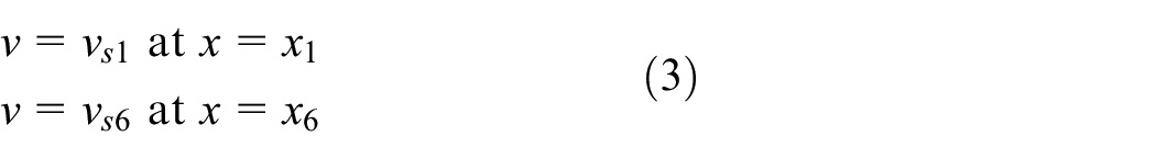
The first kind of constraint equations was that the deflect function should be equal to the values of the measured displacements during the experiment at the corresponding sections. As illustrated in Figure 9, the constraint equations about the measured displacements at the sections S1 and S6 were
At the sections with the temperature measurements (S2, S3, S4, and S5), the vertical gradient of temperature resulted in the different axial thermal expansions of the different vertical position of the section and finally caused the bending of the section. According to the thermal effect on the bending of beam, 15 the relationships between the measured temperature difference at measured sections and the deflections of the rotor could be formulated as

Here,
Depart from the displacements at the measured sections, the model rotor had zero displacement at the two rotor supports. Therefore, the corresponding constraint equations are

As given in equations (3)–(5), there are four constraint equations of the displacements and four equations for the second derivative of the rotor deflection. They were to be applied to determine the terms and the coefficients of the polynomial function for the thermal bow of the rotor.
The detailed form of the function for the bowed rotor
According to equation (2) and the number of the constraint equations, the detailed formulation of the deflection of the bowed rotor could be formulated. As there were two constraint equations on displacements (equation (3)), four constraint equations on the temperature differences at four sections (equation (4)), and two constraint equations at two bearings (equation (5)), the seventh-order polynomial functions were assumed to describe the bow shape of the rotor

The eight parameters in equation (6) should be solved by the constraint equations. It should be noted that in the fitting process, it is assumed that there is no error at the measured sections. The best way of fitting is to use all of the measured data to determine the coefficients in the polynomial. The seventh-order polynomial was also compared with the sixth- and fifth-order polynomials. Results show that results of the sixth-order polynomial function are similar to that of the seventh-order polynomial, and the error of the sixth-order polynomial is less than 7.174%. There is little difference between the fifth-order polynomial and the seventh-order polynomial. The maximum error between the fifth-order polynomial and the seventh-order polynomial functions is about 8.206%. The comparisons indicate that the more sections used, the better fitting results could be obtained for the bow shape of the rotor.
With the geometry of the model rotor, the measured temperature, and the displacement data, the constraint equations (3)–(5) could be determined, with which the coefficients in equation (6) could be solved. The detailed shape of the bowed rotor could be obtained by the procedure given in Figure 10.

The procedure to determine the detailed function for the thermal bow of the rotor.
Results and discussion
With the detailed polynomial function for the thermal bow of the rotor, the lateral displacement of every axial position of the rotor could be obtained. The thermal bow of the rotor was a time-dependent problem, and the measured temperature and displacements during the experiments were varying with time, as shown in Figures 3–8. The detailed bow shape of the rotor varied with time during the experiment. The transient bow shape of the rotor at different time of the experiment could be obtained by the obtained polynomial function. The transient bow shape of the rotor in the natural cooling and the forced cooling experiments were to be analyzed in this section.
The rotor bow shape in the experiment with natural cooling
For the case of natural cooling with the 200, 250, and 300°C heating, the bow shape of the model rotor at several typical time points is plotted in Figures 11–13, respectively. The model rotor had the maximum deflection at the middle of the span. The measured displacements at the sections near the rotor supports were about one-fourth to one-fifth of the maximum deflection of the rotor.
The bow shape of the rotor at different time in the experiment of the 200°C heating with natural cooling.

The bow shape of the rotor at different time in the experiment of the 250°C heating with natural cooling.
The bow shape of the rotor at different time in the experiment of the 300°C heating with natural cooling.
The comparisons of the cases with different heat temperatures indicated that the heating temperature had apparent effect on the deflection of the rotor. The greater heating temperature would result in greater temperature differences at the sections of the rotor (as shown in Figure 4) and finally caused the greater deflection of the rotor.
The rotor bow shape in experiment with forced cooling
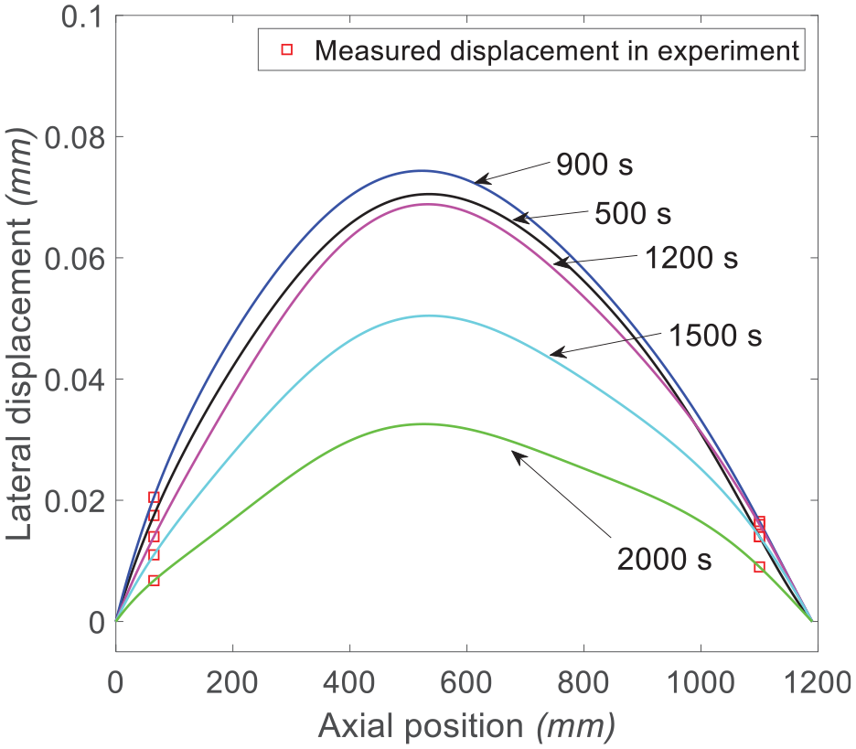
The bow shape of the rotor in cases of the experiment with the forced cooling could be obtained by the proposed method as well. As plotted in Figures 14–16, the predicted bow shapes of the rotor under the heating temperature of 200, 250, and 300°C were plotted.

The bow shape of the rotor at different time in the experiment of the 200°C heating with forced cooling.

The bow shape of the rotor at different time in the experiment of the 250°C heating with forced cooling.

The bow shape of the rotor at different time in the experiment of the 300°C heating with forced cooling.
Before the heater was turned off, the bow shape of the rotor was similar to that of the natural cooling case. However, the deflection of the model rotor decreased much quickly in the forced cooling case. After about 2000 s forced cooling, the thermal bow of the rotor almost disappeared for the 200 and 250°C heating. The difference between the forced cooling case and the natural cooling case was to be analyzed in the following section.
The effect of cooling method on the deflection of the rotor
The maximum of the deflection of the rotor during the experiments could be obtained. The comparisons between the natural cooling experiment and the forced cooling experiment would reveal the effect of the cooling method on the reduction in the thermal bow.
With the method proposed in this work, the maximum deflection of the rotor was obtained. The cases of the natural cooling and the forced cooling under different heating temperatures were compared, as shown in Figures 17–19.

The variation of the maximum deflection of the rotor with time in the experiment of the 200°C heating.
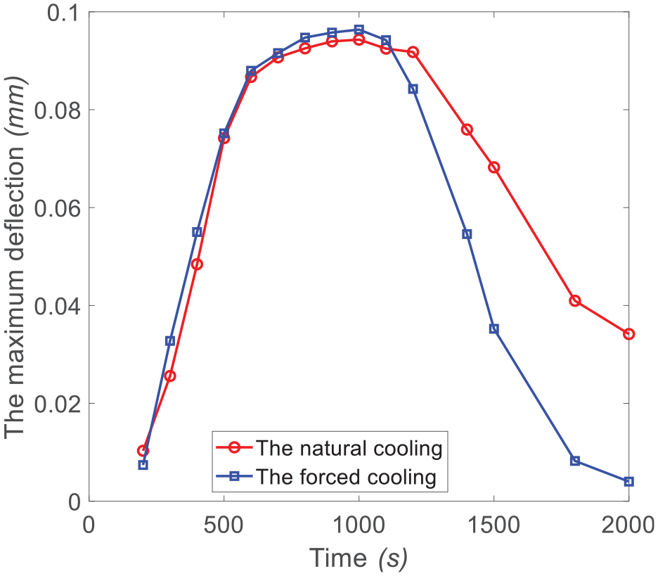
The variation of the maximum deflection of the rotor with time in the experiment of the 250°C heating.

The variation of the maximum deflection of the rotor with time in the experiment of the 300°C heating.
Compared to the natural cooling, the forced cooling could reduce the maximum deflection of the rotor quickly in a short time. Take the 300°C heating, for example, at the 1300 s of the experiment, the maximum deflection of the rotor was about 0.058 mm, while it was 0.02234 mm in the force cooling case. The force cooling was an effective method to reduce the thermal bow of the rotor, which could be helpful in engineering to eliminate the thermal bow of rotor in the aeroengine in a short time.
The eccentricities of the disks on the rotor
In the analysis of the dynamics of the bowed rotor, the eccentricities of the disks (the three compressor disks and the turbine disk, as illustrated in Figure 20) were required to compute the unbalance excitation force. With the proposed method in this work, the transient deflections of the disks during the thermal bow experiment could be obtained.

Illustration of the disks on the model rotor.
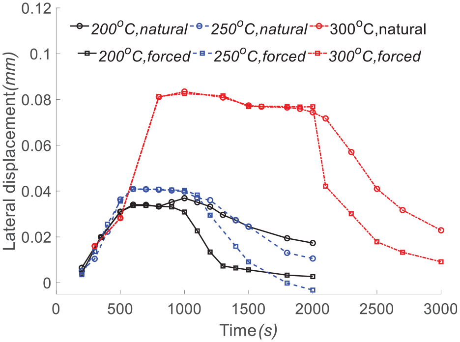
As shown in Figures 21–24, the variations of the eccentricities of the disks with time are plotted.
The variation of the lateral displacement of the compressor disk 1 with time in different experiments.

The variation of the lateral displacement of the compressor disk 2 with time in different experiments.

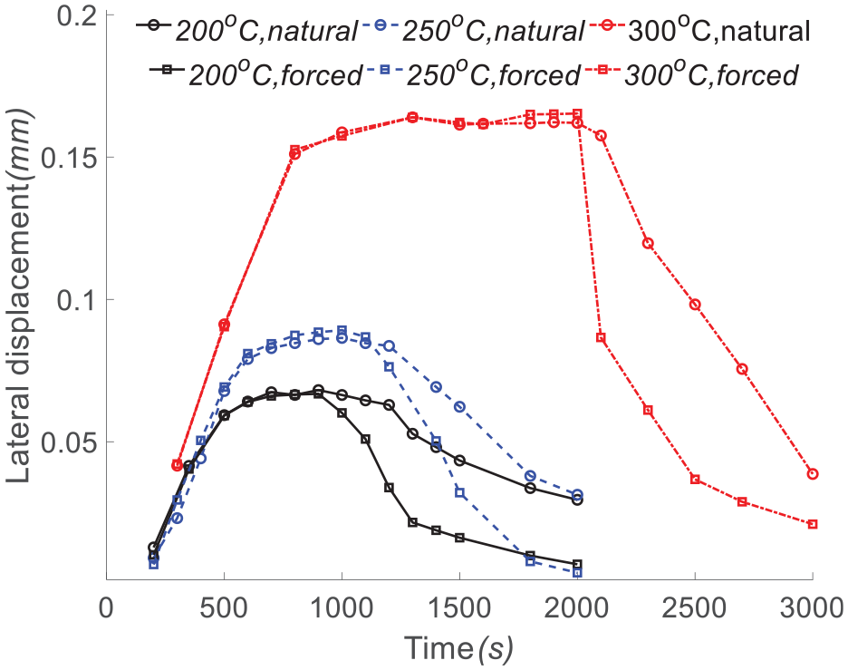
The variation of the lateral displacement of the compressor disk 3 with time in different experiments.
The variation of the lateral displacement of the turbine disk with time in different experiments.
It was obvious that the greater heating temperature would lead to greater eccentricities of the disks. This was due to the greater vertical temperature differences at the sections. In the experiment of 300°C heating, the maximum deflection of the third compressor disk and the turbine disk reached about 0.15 mm, which would lead to great unbalance excitation forces on the rotor during the restart of the aeroengine.
The eccentricities of the disks decreased when the heater was shutdown. The forced cooling had obvious effect on the reduction in the thermal bow of the rotor after the shutdown of the heater, especially in the short period just after the shutdown of the heater. The eccentricities of the disks decreased rapidly when the force cooling was started, while speed of the reduction gradually decreased.
The analysis of the maximum deflection of the rotor and the eccentricities of the disks in the experiments indicated that the proposed method in this work was capable to predict the details of the bowed rotor, which could bridge the thermal bow experiment and the dynamics of the bowed rotor.
Conclusion
The deflection of the bowed rotor during the thermal bow experiment was an important parameter to bridge the natural convection phenomenon with the vibration phenomenon of the bow rotor, while the method to predict the detailed bow shape of the rotor was still missing. An effective method was proposed with the integration of the measured displacements and temperature data. The experiment was introduced and the variations of the measured temperature and displacement were analyzed. With the assumption of the polynomial expression for the bowed rotor, the measured displacement and temperature were considered in the constraint equations, and the coefficients in the polynomial function for the rotor bow shape were obtained. The transient bowed shapes of the rotor in the different cases of experiments were obtained and analyzed. The conclusions of this work could be summarized as
This polynomial function proposed in this work could predict the shape of the bowed rotor with the measured displacement and temperature data in the experiments. The order of the polynomial depends on the numbers of measured sections in the experiment. The bow shape of the model rotor in the experiment was predicted well by the proposed method.
The maximum of deflection of the rotor during the experiment occurred around the middle of the span. The maximum deflection was about four to five times of the measured displacement at the sections near the rotor support.
The forced cooling could reduce the thermal bow quickly than the natural cooling.
The transient eccentricities of the disks on the rotor were obtained and analyzed, which provided a bridge between the measured data in the thermal bow experiment and the dynamical analysis of the thermal bowed rotor.
Footnotes
Handling Editor: Francesc Pozo
Declaration of conflicting interests
The author(s) declared no potential conflicts of interest with respect to the research, authorship, and/or publication of this article.
Funding
The author(s) disclosed receipt of the following financial support for the research, authorship, and/or publication of this article: This research work was financially supported by the National Science and Technology Major Project (Grant No. 2017-IV-0008-0045) and Natural Science Foundation of China (Grant No. 11602071).