This correspondence proposes a jointly-designed quasi-cyclic (QC) low-density parity-check (LDPC)-coded multi-relay cooperation with a destination node realized by multiple receive antennas. First, a deterministic approach is utilized to construct different classes of binary QC-LDPC codes with no length-4 cycles. Existing methods put some limitations in terms of code length and rate in order to provide high error-correction performance. Therefore, this article gives three classes of QC-LDPC codes based on a combinatoric design approach, known as cyclic difference packing (CDP), with flexibility in terms of code-length and rate selection. Second, the proposed CDP-based construction is utilized to jointly-design QC-LDPC codes for coded-relay cooperation. At the receiver, the destination node is realized by multiple receive antennas, where maximal-ratio combining (MRC) and sum-product algorithm (SPA)-based joint iterative decoding are utilized to decode the corrupted sequences coming from the source and relay nodes. Simulation results show that the proposed QC-LDPC coded-relay cooperations outperform their counterparts with a coding gain of about 0.25 dB at bit-error rate (BER) over a Rayleigh fading channel in the presence of additive white Gaussian noise. Furthermore, the extrinsic-information transfer (EXIT) chart analysis has been used to detect the convergence threshold of proposed jointly-designed QC-LDPC codes. Numerical analysis shows that the proposed jointly-designed QC-LDPC codes provide a better convergence as compared to their counterparts under the same conditions.
It is globally known that the objective of next-generation wireless communication systems is to handle high-speed data rate and spectral efficiency by reducing power cost, lower latency, and better convergence, which may require a new broadband spectrum due to the limited frequency resources of the current wireless spectrum. As a result, several problems arise such as degraded coverage and fading, which may lead to prominent reduction in the power of received signal at receiver. Multiple-input multiple-output (MIMO) has been recognized as an effective approach to combat the effect of fading by offering diversity.1,2 However, for some practical scenarios in wireless communication (e.g. wireless sensor networks), it is not feasible to realize multiple antennas due to the hardware limitations of the device. To solve this critical problem, cooperative communication, also known as virtual MIMO, is determined where the devices with single antenna terminals can share their antennas to acquire multiplexing gain and diversity.3–5 Therefore, virtual MIMO has been adopted by many wireless communication systems (e.g. wireless sensor networks, ad hoc networks). Also, in-cell mobile nodes can share their antennas for data transmission by establishing a virtual MIMO network. Three fundamental protocols for cooperative communication, amplify-and-forward (AF), estimate-and-forward (EF), and decode-and-forward (DF) have been presented in the literature.6–8 In an AF cooperation, the relay node broadcasts only the amplified version of the signal received from the source node, where the strength of transmitted signals is controlled by the amplification or scaling coefficients at the relay node. In an EF approach, the signals received from the source node are first estimated by the relay nodes based on some hard-decision statistics, then these estimated signals are transmitted to the destination node. Generally, an AF cooperation protocol seems to be more attractive as compared to an EF approach because it does not require extra computational complexity for hard-decision detection in the relay node. However, a serious flaw of an AF cooperation is that it also amplifies the noise received from source-to-relay broadcast channel (S–R) and sends it to the destination node. On the other hand, both AF and EF cooperation protocols are not feasible for low bit-error rate (BER) applications.9
Recently, many wireless communication systems have adopted low-density parity-check (LDPC)10 codes as a primary choice because of their excellent error correction performance and low-cost iterative decoding over different communication channels. In addition to higher error-correction capability, LDPC codes provide a flexible spectrum in terms of code length and rate selection. The null space of a parity-check matrix gives a regular LDPC code if it has constant column-weight and constant row-weight . If has variable column and/or row weight, then its null space gives an irregular LDPC code. The null space of a parity-check matrix gives a QC-LDPC code if it consists of an array of circulant matrices over a finite field .11,12 If a parity-check matrix satisfies a constraint that no two rows or columns can overlap, in terms of a nonzero element, at more than one positions, then this constraint is known as row–column (RC) constraint which ensures that the parity-check matrix has a girth of at least . The construction spectrum of LDPC codes is divided into two categories: (a) computer-based LDPC codes are designed based on random construction methods such as progressive edge growth LDPC (PEG-LDPC)13 codes and protograph-based LDPC14 codes; (b) structured LDPC codes (e.g. quasi-cyclic LDPC (QC-LDPC)) are constructed based on deterministic methods such as finite fields,15–18 finite geometries,19 and combinatorial designs.20–26 Quasi-cyclic or architecture-aware LDPC codes have been adopted by many communication standards because of their efficient architecture, which reduces computational cost of an encoder and decoder.
A technique called coded cooperation is used for high error performance applications; this is channel coding coupled with the conventional relay cooperation. The conventional AF and EF user cooperation protocols have been replaced by coded cooperation by employing forward error correction in the relay and destination node. In coded relay cooperative communication, each relay node instead of transmitting the whole data frame, only sends the redundant parity bits to the destination node. The performance of coded cooperation has been investigated based on turbo and LDPC codes.9,27–36 However, LDPC-coded cooperation provides more advantages over turbo-coded cooperation in terms of low-cost decoding and delay for hardware implementation of decoder.9 To the best of our knowledge, most of the previous studies have investigated LDPC-coded cooperation by utilizing random LDPC codes. However, the investigation on QC-LDPC-coded cooperation is rarely discussed.30,34–36 As compared to QC-LDPC-coded cooperation, random LDPC-coded cooperation provides a limited spectrum in terms of code length and rate with quadratic encoding complexity. However, QC-LDPC-coded cooperation provides more flexibility in terms of code length and rate selection with linear encoding complexity. In this correspondence, we propose a jointly designed QC-LDPC-coded multi-relay cooperation with destination node realized by multiple receive antennas over a Rayleigh fading channel in the presence of additive white Gaussian noise. First, a combinatorial construction of QC-LDPC codes based on cyclic difference packing (CDP)37–43 gives three classes of binary QC-LDPC codes with no length-4 cycles. Second, the proposed CDP-based construction is utilized to jointly design QC-LDPC codes with no length-4 cycles for coded-relay cooperation. Also, the destination node is realized by multiple receive antennas, where maximal-ratio combining (MRC) and sum-product algorithm (SPA)-based joint iterative decoding are utilized to decode the corrupted sequences coming from the source and relay nodes in two different time frames. Based on the simulation results, the proposed QC-LDPC-coded cooperations outperform their counterparts by providing a coding gain of about dB at BER with five decoding iterations over a Rayleigh fading channel in the presence of additive white Gaussian noise. Furthermore, an analytical tool called exit-information transfer (EXIT) chart is used to detect the convergence threshold of proposed jointly designed QC-LDPC codes. Numerical analysis shows that the proposed jointly designed QC-LDPC codes provide a better convergence as compared to their counterparts under the same conditions.
The rest of this article is organized as follows. Basic concepts about the QC-LDPC coded-relay cooperation are given in the section “Coded-relay cooperation.” A brief discussion about the existence and construction of CDP is presented in the section “Cyclic difference packing.” The section “CDP-based construction of QC-LDPC codes” presents a CDP-based construction of QC-LDPC codes. Proposed construction of jointly designed QC-LDPC codes for coded-relay cooperation is given in the section “Jointly designed QC-LDPC coded cooperation.” The section “Maximal-ratio combining for multiple receive antennas” presents a diversity combining method based on maximal-ratio combining at receiver. Numerical results are presented in the section “Numerical results.” Finally, the conclusion of this article is presented in the section “Conclusion and remarks.”
Coded-relay cooperation
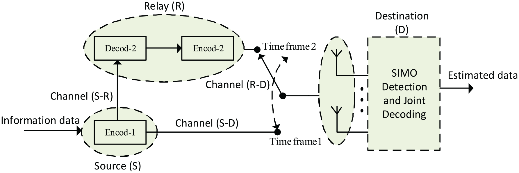
A fundamental model for one-relay coded cooperative communication system equipped with multiple receive antennas and consisting of three nodes such as source S, relay R, and destination D is depicted in Figure 1. All these nodes are supposed to have only one antenna and they communicate with each other over a half-duplex Rayleigh fading channel.
A fundamental model for one-relay coded cooperation over a Rayleigh fading channel.
The information transmission from source to destination is divided into two consecutive time frames. In the first time frame, the source node (S) encodes the information data by first encoder, denoted as Encod-1, and sends to the relay node (R) and destination node (D) simultaneously over broadcast channels (S–R) and (S–D), respectively. In the second time frame, the decoder in the relay node, denoted as Decod-2, first decodes the data received from the source node. Then, the encoder in the relay node, denoted as Encod-2, encodes the estimated data and sends whole or a part of the coded symbols to the destination node over a broadcast channel (R–D). For ideal coded cooperative communication, it is assumed that the decoder in the relay node has successfully decoded the information sent from the source node.
In one-relay coded cooperation, two distinct QC-LDPC codes and defined by the null space of two parity-check matrices and were utilized to realize the source and relay node, respectively. The code in systematic form is , where denotes the redundant parity data with length . The relay node first decodes the information received from the source node, then the Encod-2 encodes the estimated data by adding new redundant parity bits with length using parity-check matrix . Also, both coded sequences from Encod-1 and Encod-2 are correlated in source and relay nodes, respectively. Specifically, both coded sequences depend on their common information data bits. Both coded sequences are completely correlated if Decod-2 successfully decodes the message sent from source node. If there exist some errors in the decoded sequence from Decod-2, then both coded sequences are partially correlated.
In the destination node, multiple receive antennas are installed at the receiver to receive the corrupted signals coming from source and relay nodes in their respective time slots. The potential diversity gain of coded cooperation by utilizing multiple receive antennas in the destination is same as well as an ordinary MIMO system over a Rayleigh-fading channel in the presence of additive white Gaussian noise. Finally, a joint iterative decoder uses the parity-check matrix , comprised of and , to jointly decode the messages coming from the source and relay node. Note that the relay node sends only the redundant parity data to the destination node as it has already received the information bits from the source node.
It is important to note that a coded cooperative communication system behaves like an ordinary point-to-point communication system if the relay node does not process the information data received from the source node. Furthermore, a one-relay coded cooperation can be easily extended to a multi-relay coded cooperation with -level , as depicted in Figure 2. In multi-relay coded cooperation, each level contains some relay nodes where the relay nodes in higher levels can receive information only from relay nodes in lower levels. Specifically, the source nose sends its original message to all the relay nodes and the destination node. However, the destination node receives information from the source and all the relay nodes.
Illustrative diagram for a generalized -level multi-relay coded cooperation.
Cyclic difference packing
Fundamental concepts
CDP designs are a special type of balanced incomplete block design (BIBD), so we begin with the definition of BIBD.
Definition 1
A pair is called a design, where denotes a set of varieties and denotes the nonempty subsets of , called blocks.44 Suppose , , and are positive integers such that . A design is called -BIBD if all of the following properties hold:
.
Each nonempty subset (block) of have varieties.
Each pair of elements exists in exactly subsets of .
Definition 2
Let be positive integers with .44 A pair is called a packing design or briefly -PD, where and denotes the nonempty -subsets of , called blocks, such that every -subset of distinct elements from appears in at most blocks.
Let be a packing design. Suppose is a permutation on such that for any block , , then is called an automorphism of the packing design . A packing design having cyclic automorphism is known as cyclic packing design, where cyclic automorphism is a bijection . Suppose is a block of cyclic packing design , then the block orbit consists of the following distinct blocks
where . A block orbit containing distinct blocks is called full orbit; otherwise short orbit. Any fixed block from each block orbit is called a base block.
Let denote the set of all base blocks of a cyclic packing design. Then, the pair is called a cyclic difference packing or briefly a -CDP. A -CDP with base blocks is called maximum -CDP. In the literature,45 it has already been shown that an optimal Optical Orthogonal Code or briefly -OOC is equivalent to cyclic difference packing or briefly -CDP
Theorem 1
An optimal -OOC is equivalent to a maximum -CDP if and only if .45
Definition 3
A family of binary codewords is called an -OOC if the following correlation properties hold:44
Autocorrelation.
, for and .
Cross-correlation.
, for , with , and for any integer .
where the subscripts are treated over . An -OOC is said to be optimal if it has
codewords.
Existence of cyclic difference packing
The construction of a maximum -CDP gives its corresponding optimal -OOC. Some known results about the existence of a maximum -CDP are given as follows.
There exists an optimal -CDP for any nonnegative integer , where denotes the product of prime factors congruent to .38
There exists an optimal -regular -CDP, where and .39
There exists an optimal -regular -CDP, where and .39
Next, we construct three classes of QC-LDPC codes by utilizing the maximum -CDP’s with .
CDP-based construction of QC-LDPC codes
A design theoretic construction of binary QC-LDPC codes based on the maximum -CDP is provided. Consider a base matrix given by equation (1)
where each represents a circulant matrix, . Each row of , , is the outcome of the cyclic-shift of the previous row, where the first row of is resulted from one of the base blocks of maximum -CDP with . The base matrix has a rate of at least and a minimum distance lower bounded by .
Example 1
Consider an optimal -CDP with for . The base blocks for a -CDP are: , , , .
Consequently, a base matrix is obtained from above construction method. To make the idea more clear, consider a submatrix of base matrix given as follows
where and , . Note that the submatrix has length- cycles if and only if mod .12 Clearly, the above base matrix does not satisfy the condition mod . Consequently, the Tanner graph representation of the above base matrix has no length- cycles.
CDP-based QC-LDPC codes: class-I
Let be a finite field with elements. For each nonzero element , , form a -tuple over , , with all the components of are zero except the ith component .11 The subscript stands for the binary. This -tuple is referred as the binary location-vector of . The binary location vector of 0-element is .
Let be an element of . If denotes the binary location vector of , then the right cyclic-shift of gives the binary location vector of element , where denotes the primitive element of . Then the -tuples of , , ,…, , give a circular permutation matrix . Matrix is referred as -fold binary dispersion11 of over . The -fold matrix dispersion of additive identity of is a all-zero matrix over .
Next, all the entries of base matrix given by equation (1) are replaced by their -fold matrix dispersions over . We obtain an array given as follows
where is a circular permutation matrix over , for and . Array gives a matrix over . Clearly, matrix fulfills the RC-constraint. Consequently, the null space of gives a length- cycle-free QC-LDPC code with a rate lower bounded by .
CDP-based QC-LDPC codes: class-II
A class of binary length-4 cycle-free QC-LDPC codes is constructed based on the incidence matrices obtained from maximum -CDP with . A design with blocks, , satisfying the following properties is called a -BIBD: (a) each entry in participates in blocks; (b) each pair of the entries in participates in exactly blocks of ; and (c) the size of each block is smaller than . A -BIBD can also be represented by a matrix over
where matrix is known as incidence matrix.11 An incidence matrix must satisfy the following properties: (a) the column-weight of an incidence matrix is equal to ; (b) the row-weight of an incidence matrix is equal to ; and (c) any two rows or columns of have -element in common at most positions.
The incidence matrix of this BIBD is given as follows
The cyclic shift of each row returns a next row of and the first row is obtained by the cyclic shift of last row. Also, the downward cyclic shift of each column of gives a column on its right. So, the matrix is a circulant permutation matrix over . Note that the circulant permutation matrix fulfills all of the required properties of parity-check matrix and satisfies the RC-constraint. Therefore, the null space of gives a LDPC code with a girth of at least .
Based on a maximum -CDP with , consider a incidence matrix obtained from base blocks. The incidence matrix can be arranged in a cyclic manner consisting of a array of circulant submatrices given as follows
where each , , represents a circulant submatrix over . Note that the matrix fulfills all of the desired properties of a parity-check matrix. Consequently, the null space of matrix gives a QC-LDPC code with no length-4 cycles and a rate of at least .
CDP-based QC-LDPC codes: class-III
In the section “CDP-based QC-LDPC codes: class-II,” a class of binary QC-LDPC codes has been constructed based on incidence matrices. The circulant decomposition11 of each circulant matrix gives a new class of binary QC-LDPC codes. Consider a matrix given by equation (4), where each represents a circulant submatrix obtained from -CDP with and , for .
Let be the first row of circulant matrix over . Decompose into six rows, , ,…, , by distributing six -elements of among the six new rows. The first -element of is placed in , the second 1-element of is placed in , …, and the sixth -element of is placed in . For each new row , form a circulant matrix by using and its right cyclic shifts. This decomposition and cyclic shifting of each circulant , , gives six circulant matrices, , , …, . These six circulant matrices are called descendants of .
Let . A array of circulant matrices is given as follows
where is a matrix over . is constructed based on a maximum -CDP with and fulfills all of the desired properties of a parity-check matrix. Consequently, the null space of gives a QC-LDPC code with no length-4 cycles and rate lower bounded by .
Jointly designed QC-LDPC coded cooperation
One-relay coded cooperation
This section provides a joint design of QC-LDPC codes for one-relay coded cooperation. Jointly designed QC-LDPC codes are constructed based on the proposed three classes of binary length-4 cycles free QC-LDPC codes in the sections “CDP-based QC-LDPC codes: class-I,”“CDP-based QC-LDPC codes: class-II,” and “CDP-based QC-LDPC codes: class-III,” respectively. Jointly designed QC-LDPC codes are jointly decoded by a joint iterative decoder in the destination over a Rayleigh fading channel in the presence of additive white Gaussian noise.
Suppose the source and relay nodes of a one-relay coded cooperation are realized by two distinct QC-LDPC codes defined by the null space of two parity-check matrices and , respectively. Both parity-check matrices and are designed based on the proposed CDP-based construction of QC-LDPC codes given by equations (2), (4), and (6). QC-LDPC codes defined by the null space of and are regular and denoted as and , where and denote the number of 1’s in each row and column of and , respectively.
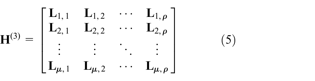
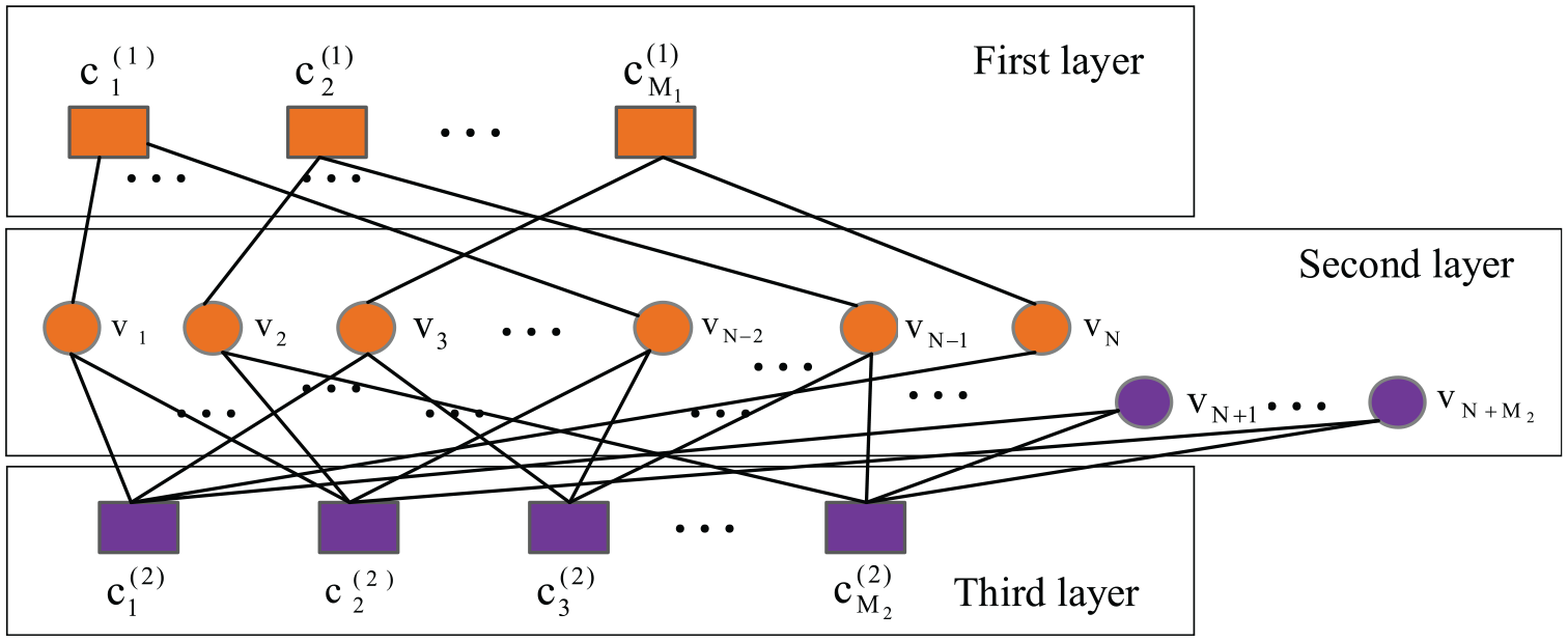
In one-relay coded cooperation, joint iterative decoding can be applied for double regular QC-LDPC codes and to decode the corrupted sequences form the source and relay nodes over the broadcast channels (S–D) and (R–D), respectively. A general joint triple-layer Tanner graph utilized for joint iterative decoding for one-relay coded cooperation is given in Figure 3. In one-relay coded cooperation, the overall code rate from the destination is , where and denotes the code rates of and , respectively. In particular, the resultant parity-check matrix for one-relay cooperation is given as follows
where are the parity-check matrices of and , respectively, where , , and . The null space of gives an irregular QC-LDPC code with no length-4 cycles.
A joint triple-layer Tanner graph for one-relay coded cooperation.
Multi-relay coded cooperation
The idea for a one-relay coded cooperation can be easily extended to a multi-relay coded cooperation. A generalized -level multi-relay cooperation is shown in Figure 2. A multi-relay coded cooperation using multi-QC-LDPC codes for the source and relay nodes and joint iterative decoding in the destination is a straightforward extension of aforementioned one-relay coded cooperation over a Rayleigh-fading channel in the presence of additive-white Gaussian noise. In multi-relay coded cooperation, each level has some relay nodes and only the relays in higher levels receive information from the relay nodes in lower levels. However, the destination node receives the incoming messages from the source and all the relay nodes.
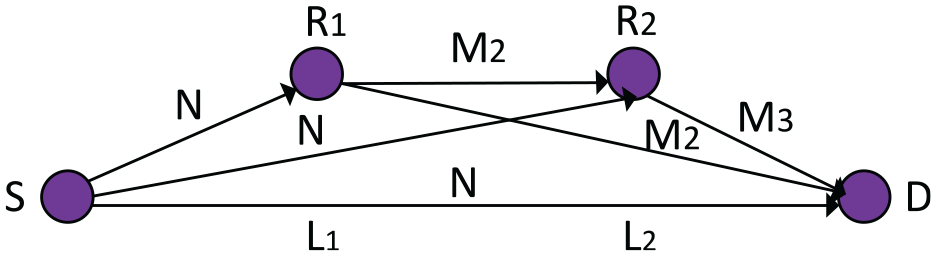
To make the description more simple, we focus on a two-level multi-relay coded cooperation where each level contains only one relay, as depicted in Figure 4. In this two-level multi-relay coded cooperation, suppose the source node, and the first and second relay nodes are realized by three distinct QC-LDPC codes , , defined by the null space of three parity-check matrices , , and , respectively.
A two-level multi-relay coded cooperation with one relay in each level.
In two-level multi-relay coded cooperation, joint iterative decoding can be applied for triple regular QC-LDPC codes , , to decode the corrupted sequences coming from the source node, and the first and second relay nodes over Rayleigh-fading channel in the presence of additive-white Gaussian noise. A joint Tanner graph for two-level multi-relay cooperation utilized for joint iterative decoding in the destination is depicted in Figure 5. The overall code rate from the destination is , where , , and denotes the code rates of source, first relay, and second relay, respectively. The resultant parity-check matrix is given as follows
where , and are the parity-check matrices of , , and , respectively. The null space of gives an irregular QC-LDPC code with no length-4 cycles.
A Joint Tanner graph used to define two-relay coded cooperation over Rayleigh fading channel.
SPA-based joint iterative decoding
At the receiver, the output data obtained from multiplexer can be expressed as . Assuming binary-phase-shift-keying (BPSK) modulation over a Rayleigh fading channel, let are processed as the inputs messages for joint-iterative decoder:
1. Initialization.
The log-likelihood ratio (LLR) can be computed as
where denotes the power gain of signal received from the relay node to that received from the source node.
Let the a-posteriori LLR for is computed as
Note that if all of the check-nodes (except the ith check-node ) connected to a variable-node are satisfied simultaneously, then .
2. Check-node update.
The extrinsic information sent from check-node (first or third layer of joint Tanner graph) to a variable-node can be computed as
where represents the set of variable-nodes connected to the check-node excluding .
3. Variable-node update.
Extrinsic information sent from a variable-node (participating in the first layer of joint Tanner graph) to a check-node can be computed as
Similarly, extrinsic information updated by a variable-node for a check-node (participating in the third layer of joint Tanner graph) can be computed as
4. Final LLR.
Repeat horizontal and vertical processing in step (2) and step (3) for a maximum number of iterations of decoder. Consequently, the final a-posteriori LLR can be computed as
Finally, if , the decoded bit , otherwise .
Maximal-ratio combining for multiple receive antennas
To achieve receive diversity for the proposed coded-relay cooperative communication, the destination node is realized by multiple receive antennas to combat the effect of fading and noise resulted from constituent Rayleigh fading channels (S–D) and (R–D) for the source and relay nodes, respectively. The source and relay nodes are assumed to have a single antenna to broadcast their coded sequences to the destination node in a unique time frame over a half-duplex Rayleigh fading channel in the presence of additive-white Gaussian noise.
For a single-input-multiple-output (SIMO) detection in the destination node, a special case of matrix-matched filter known as MRC is utilized to filter the signals from multiple receive antennas. The MRC is an efficient diversity combining method to enhance the signal power by filtering the outputs from multiple received antennas. In the proposed coded-relay cooperation, the diversity combing process consisting of two MRCs, denoted as MRC-1 and MRC-2, is given in Figure 6. Note that MRC-1 and MRC-2 handle the corrupted sequences coming from the source and relay nodes in two different time slots.
Illustrative diagram for maximal-ratio combining and joint iterative decoding for multiple receive antennas in the destination.
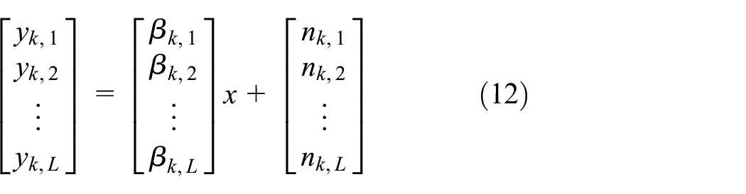
Let be the kth signal received at antennas, for or 2 to denote the signals coming from the source and relay nodes, respectively. Suppose all the coded sequences, in one-relay codded cooperation, transmitted by the source and relay node suffer from channel fading and additive-white Gaussian noise simultaneously. Since both MRCs perform the same filtering process for the incoming signals from the source and relay nodes, the superscript of is omitted in the sequel. Thus, the vector system model for the kth signal received at antennas becomes
Above system model in equation (12) can be represented by the following equation
where denotes the transmitted codeword sent by the source or relay node over constituent broadcast channels in the presence of additive-white Gaussian noise. and represent two complex column vectors for additive-white Gaussian noise and channel fading, respectively, where and are complex Gaussian random variables with zero mean and variance and , respectively. Since are Gaussian in nature, we assume that the noise on any pair of antennas is uncorrelated, that is, , .
In the proposed coded-relay cooperation, the combining of at receive antennas in the destination node is given as follows
where denote the complex combining weights at the receiver. The above equation (14) can be simplified as
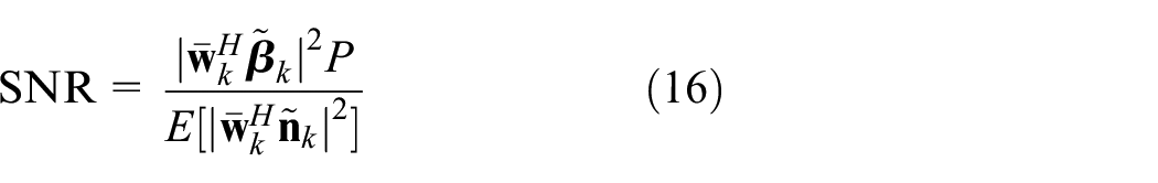
Next, the signal-to-noise ratio (SNR) at receiver can be computed as
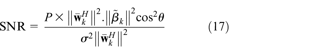
where denotes the power of transmitted signal sent by the source or relay node. Both the numerator and the denominator in equation (16) can be further simplified. Thus, the SNR at the receiver becomes
It is important to note that is maximum when is maximum, where is an angle between and . Since the maximum value of occurs at , for to be maximized, and have to be pointing in the same direction.
To maximize the SNR in the destination node, the vector has to be proportional to the vector . Specifically, the vector can be set such that norm of the vector is unity
where the vector is called maximal-ratio combiner.
Finally, the outputs (i = 1, 2) from MRC-1 and MRC-2, as depicted in Figure 6, are multiplexed and sent to an iterative decoder to jointly decode the corrupted sequences coming from the source and relay nodes in their respective time frames.
Numerical results
This section investigates the error correction performance of proposed jointly designed QC-LDPC coded-relay cooperation with multiple receive antennas in the destination node, where an efficient diversity combining method known as MRC is utilized to filter the outputs from multiple receive antennas. Simulation results are obtained by SPA-based joint iterative decoding with BPSK transmission over Rayleigh fading channel in the presence of additive-white Gaussian noise.
Performance comparison of proposed jointly designed QC-LDPC-coded cooperations and their competitors with different decoding iterations and a fixed number of receive antennas in the destination
This section investigates the error-correction performance comparison of a proposed jointly designed QC-LDPC code for one-relay coded cooperation and their competitors under two and five decoding iterations and four receive antennas in the destination node. The BER performance of proposed jointly designed QC-LDPC-coded cooperation and their counterparts using SPA-based joint iterative decoding and BPSK transmission over a Rayleigh fading channel is given in Figure 7. Simulation results show that the proposed jointly designed QC-LDPC-coded cooperations perform as well as their competitors in lower SNR region but outperform in higher SNR region under the same conditions over a Rayleigh fading channel in the presence of additive-white Gaussian noise. The relevant parameters for the component QC-LDPC codes adopted for jointly designed QC-LDPC code and their counterparts are given in Table 1, where the overall code rate is from the destination.
BER performance comparison of proposed jointly designed QC-LDPC-coded one-relay cooperation and its competitors over a Rayleigh fading channel under two and five decoding iterations and four receive antennas in the destination.
Relevant parameters for the proposed component QC-LDPC codes and their competitors used in Figure 7.
Performance of proposed jointly designed QC-LDPC coded one-relay cooperation with different decoding iterations and a fixed number of receive antennas in the destination
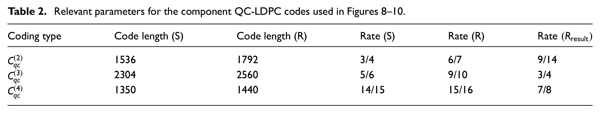
The error-correction performance of a proposed jointly designed QC-LDPC code investigated with four receive antennas in the destination node and two, three, four, and five decoding iterations is shown in Figure 8. It is important to note that the proposed jointly designed QC-LDPC coded cooperation provides excellent BER performance with SPA-based joint iterative decoding for various decoding iterations over Rayleigh fading channel in the presence of additive-white Gaussian noise. For instance, the third decoding iteration gives about dB gain over the second iteration at BER . Similarly, at BER , about dB gain is achieved for the fourth decoding iteration over the third decoding iteration, and it is about dB for the fifth decoding iteration over the fourth decoding iteration at BER . Simulation results show that the proposed jointly designed QC-LDPC-coded cooperation provides an excellent error correcting performance over a Rayleigh fading channel. The relevant parameters for component QC-LDPC codes adopted for jointly designed QC-LDPC codes are given in Table 2. Note that the overall code rate, , is from the destination.
BER performance of proposed jointly designed QC-LDPC-coded one-relay cooperation under two, three, four, and five decoding iterations and four receive antennas in the destination.
Relevant parameters for the component QC-LDPC codes used in Figures 8–10.
Coding type
Code length (S)
Code length (R)
Rate (S)
Rate (R)
1536
1792
3/4
6/7
9/14
2304
2560
5/6
9/10
3/4
14/15
15/16
7/8
Performance of proposed jointly designed QC-LDPC-coded one-relay cooperation with different number of receive antennas and a fixed number of decoding iterations
This section investigates the error-correction performance of a proposed jointly designed QC-LDPC code with four decoding iterations and one, two, three, and four receive antennas in the destination node. The BER performance of proposed coded one-relay cooperation using SPA-based joint iterative decoding and BPSK transmission over a Rayleigh fading channel in the presence of additive-white Gaussian noise is given in Figure 9. Simulation results show that the proposed jointly designed QC-LDPC-coded cooperation provides an excellent BER performance for different number of receive antennas at the receiver. For instance, at BER , the proposed jointly designed coded-relay cooperation with three receive antennas provides a gain of about dB over two receive antennas in the destination. Similarly, at BER , about dB gain is achieved with four receive antennas over three receive antennas in the destination. The relevant parameters for the component QC-LDPC codes adopted for jointly designed QC-LDPC code are also given in Table 2, where the overall code rate is from the destination.
BER performance of proposed jointly designed QC-LDPC-coded one-relay cooperation with one, two, three, and four receive antennas in the destination and four decoding iterations over Rayleigh fading channel.
Performance of proposed jointly designed QC-LDPC-coded cooperation and non-coded cooperation with different decoding iterations and a fixed number of receive antennas in the destination
Figure 10 compares the error-correction performance of a proposed jointly designed coded cooperation and non-coded cooperation with two and five decoding iterations and four receive antennas under the same rate . The BER results of proposed coded and non-coded cooperation based on SPA-based joint iterative decoding over a Rayleigh fading channel are given in Figure 10. The relevant parameters for the component QC-LDPC code adopted for proposed coded cooperation are given in Table 2, where the overall code rate is . Simulation results show that the proposed coded cooperations outperform the non-coded cooperation by providing a prominent coding gain. For instance, at BER , the proposed coded cooperation provides a gain of about and dB with two and five decoding iterations, respectively.
Performance comparison of proposed jointly designed QC-LDPC-coded cooperation and non-coded cooperation under two and five decoding iterations and four receive antennas.
Performance of proposed jointly designed QC-LDPC-coded multi-relay and one-relay cooperation with different decoding iterations and a fixed number of receive antennas in the destination
Figure 11 investigates the BER performance of proposed jointly designed QC-LDPC codes and for a one-relay and two-relay coded cooperation, respectively, under two and five decoding iterations and four receive antennas in the destination node. The overall code rate for one-relay and two-relay coded cooperation is from the destination node, where the relevant parameters for component QC-LDPC codes designed for one-relay and two-relay coded cooperation are given in Table 3. Simulation results show that the error-correcting performance of two-relay coded cooperation outperforms the one-relay coded cooperation with SPA-based joint iterative over a Rayleigh fading channel in the presence of additive-white Gaussian noise. This indicates that higher error-correction performance can be achieved by using multi-relay coded cooperation under the same conditions over a Rayleigh fading channel.
BER performance of proposed jointly designed one-relay and two-relay coded cooperation under two and five decoding iterations and four receive antennas in the destination over Rayleigh fading channel.
Relevant parameters for the component QC-LDPC codes used in Figure 11.
Coding type
Code length (S)
Code length
Code length
Rate (S)
Rate
Rate
Rate
1470
1890
None
6/7
7/9
None
2/3
1470
1680
1890
6/7
7/8
8/9
2/3
EXIT chart analysis of proposed jointly designed QC-LDPC codes and their competitors under same conditions
EXIT chart analysis is an analytical tool to determine the convergence threshold of an iterative decoder. In EXIT chart analysis of LDPC codes, the set variable-nodes is referred as a variable-node decoder (VND) and the set check-nodes is referred as a check-node decoder (CND). The VND converts channel and a priori LLR from CND to a posteriori LLR. Similarly, CND converts a priori LLR from VND to a posteriori LLR at its output. Note that the a posteriori information from VND becomes the a priori information for CND. Let denote the mutual information at the output of VND and denote the mutual information at the output of CND, where the underlying assumption is that the mutual information at the output of VND and CND is a function of mutual information at their input. We refer to the literature47 for detail information about EXIT chart analysis of an iterative decoder. To predict the decoding threshold, the mutual information at the output of decoder (i.e. VND or CND) is plotted as a function of mutual information at its input. Specifically, error-free transmission is possible if the mutual information at the output of VND and CND converges to one. The EXIT chart is plotted between a priori mutual information before decoding and extrinsic mutual information after decoding. Since the VND directly depends on the channel, in the first iteration is treated as the mutual information of the channel. However, the CND does not depend on the channel like VND. Consequently, the EXIT curves of VND get higher (i.e. close to (1, 1)) for better SNR. However, the EXIT curves of CND remain constant. The wider tunnel between the EXIT curves of both decoders (VND and CND) corresponds to better decoding. It is important to note that if two curves intersect each other at any other point except (1, 1), then no successful decoding can be achieved.
In this section, the EXIT chart analysis has been utilized to predict the convergence threshold of proposed jointly designed QC-LDPC code and its competitors under same code rate . The EXIT charts of and its counterparts are depicted in Figures 12–15, respectively. Based on the numerical analysis, it can be seen that the minimum required for the convergence of is only dB. However, the minimum required for the convergence of other competitors is about dB. Consequently, the proposed jointly designed QC-LDPC codes provide a better convergence threshold as compared to their other counterparts under the same conditions.
Convergence threshold for proposed jointly designed QC-LDPC , , dB.
Convergence threshold for conventional QC-LDPC,35, dB.
Convergence threshold for conventional QC-LDPC,36, dB.
Convergence threshold for conventional QC-LDPC,30, dB.
Conclusion and remarks
In this correspondence, we proposed a jointly designed QC-LDPC-coded cooperation with multiple receive antennas in the destination, where transmit diversity, receive diversity, and coding gain are combined into one unit to decode the corrupted sequences coming from source and relay nodes in their respective time frames. First, a design theoretic approach, known as cyclic difference packing (CDP), gives three classes of binary QC-LDPC codes with no length-4 cycles by utilizing some known ingredients like binary matrix dispersion over finite fields, incidence matrices, and circulant decomposition. Second, the proposed CDP-based construction is utilized to jointly design length-4 cycle-free QC-LDPC codes for coded-relay cooperation with multiple receive antennas in the destination, where MRC and SPA-based joint iterative decoding are utilized to decode the corrupted messages coming from the source and relay nodes. Based on the numerical simulation, theoretical analysis shows that the proposed QC-LDPC-coded cooperations outperform their counterparts by providing a coding gain of about dB at BER under the same conditions over a Rayleigh fading channel in the presence of additive-white Gaussian noise. Furthermore, the EXIT chart analysis has been utilized to detect the convergence threshold of proposed jointly designed QC-LDPC codes. Numerical results show that the proposed jointly designed QC-LDPC codes provide a better convergence as compared to their counterparts under the same conditions.
Footnotes
Acknowledgements
M.A. acknowledges the support of the Chinese Academy of Sciences (CAS) and TWAS for his PhD studies at the University of Science and Technology, China, as a 2016 CAS-TWAS President’s Fellowship Awardee (CAS-TWAS No. 2016-48).
Handling Editor: Olivier Berder
Declaration of conflicting interests
The author(s) declared no potential conflicts of interest with respect to the research, authorship, and/or publication of this article.
Funding
The author(s) disclosed receipt of the following financial support for the research, authorship, and/or publication of this article: This research work was conducted by Natural Science Foundation of China under grant number 61461136002 and Key Program of National Natural Science Foundation of China under grant number 61631018.
ORCID iD
Muhammad Asif
References
1.
MehanaAHNosratiniaA.Diversity of MMSE MIMO receivers. IEEE Trans Inform Theory2012; 58: 6788–6850.
2.
KarmakarSVaranasiMK.The diversity-multiplexing tradeoff of the MIMO half-duplex relay channel. IEEE Trans Inform Theory2012; 58: 7168–7187.
3.
HunterTENosratiniaA.Diversity through coded cooperation. IEEE Trans Wirel Commun2006; 5: 283–289.
4.
AdnanSFuYJunejoNUR, et al. Sparse detection with orthogonal matching pursuit in multiuser uplink quadrature spatial modulation MIMO system. IET Commun2019; 13: 3472–3478.
5.
JohnBFalconerDDYanikomerogluH.Multi-hop diversity in wireless relaying channels. IEEE Trans Commun2004; 52: 1820–1830.
6.
SendonarisAErkipEAazhangB.User cooperation diversity. Part I. System description. IEEE Trans Commun2003; 51: 1927–1938.
7.
AzarianKGamalHESchniterP.On the achievable diversity-multiplexing tradeoff in half-duplex cooperative channels. IEEE Trans Inform Theory2005; 51: 4152–4172.
8.
LanemanJNTseDNCWornellGW.Cooperative diversity in wireless networks: efficient protocols and outrage behavior. IEEE Trans Inform Theory2004; 50: 3062–3080.
9.
YangFFChenJZongP, et al. Joint iterative decoding for pragmatic irregular LDPC-coded multi-relay cooperations. Int J Electron2011; 98(10): 1383–1397.
10.
GallagerRG.Low-density parity-check codes. IRE Trans Inform Theory1962; 8(1): 21–28.
11.
RyanWELinS.Channel codes: classical and modern. New York: Cambridge University Press, 2009.
12.
FossorierMPC. Quasi-cyclic low-density parity-check codes from circulant permutation matrices. IEEE Trans Inform Theory2004; 50: 1788–1793.
13.
HuXYEleftheriouEArnoldDM.Regular and irregular progressive edge-growth Tanner graphs. IEEE Trans Inform Theory2005; 51: 386–398.
14.
Abu-SurraSDivsalarDRyanWE.Enumerators for protograph-based ensembles of LDPC and generalized LDPC codes. IEEE Trans Inform Theory2011; 57: 858–886.
15.
TaiYYLanLZengL, et al. Algebraic construction of quasi-cyclic LDPC codes for the AWGN and erasure channels. IEEE Trans Commun2006; 54: 1765–1774.
16.
ZhangLLinSAbdel-GhaffarK, et al. Quasi-cyclic LDPC codes on cyclic subgroups of finite fields. IEEE Trans Commun2011; 59: 2330–2336.
17.
DiaoQHuangQLinS, et al. A matrix-theoretic approach for analyzing quasi-cyclic low-density parity-check codes. IEEE Trans Inform Theory2012; 58: 4030–4048.
18.
LiJLiuKLinS, et al. Algebraic quasi-cyclic LDPC codes: construction, low error-floor, large girth and a reduced-complexity decoding scheme. IEEE Trans Commun2014; 62: 2626–2637.
19.
DiaoQTaiYYLinS, et al. LDPC codes on partial geometries: construction, trapping set structure, and puncturing. IEEE Trans Inform Theory2013; 59: 7898–7914.
20.
VasicBMilenkovicO.Combinatorial constructions of low-density parity-check codes for iterative decoding. IEEE Trans Inform Theory2004; 50: 1156–1176.
21.
JohnsonSJWellerSR.Resolvable 2-designs for regular low-density parity-check codes. IEEE Trans Commun2003; 51: 1413–1419.
22.
ParkHHongSBNoJS, et al. Construction of high-rate regular quasi-cyclic LDPC codes based on cyclic difference families. IEEE Trans Commun2013; 61: 3108–3113.
23.
FalsafainHEsmaeiliM.Construction of structured regular LDPC codes: a design-theoretic approach. IEEE Trans Commun2013; 61: 1640–1647.
24.
AsifMZhouWYAjmalM, et al. A construction of high performance quasicyclic LDPC codes: a combinatoric design approach. Wirel Commun Mob Comput2019; 2019: 7468792.
25.
VafiSMajidNR.A new scheme of high performance quasi-cyclic LDPC codes with girth 6. IEEE Commun Lett2015; 19: 1666–1669.
26.
JohnsonSJWellerSR.A family of irregular LDPC codes with low encoding complexity. IEEE Commun Lett2003; 7: 79–81.
27.
RazaghiPYuW.Bilayer low-density parity-check codes for decode-and-forward in relay channels. IEEE Trans Inform Theory2007; 53: 3723–3739.
28.
CancesJPMeghdadiV.Optimized low density parity check codes designs for half duplex relay channels. IEEE Trans Wirel Commun2009; 8: 3390–3395.
29.
LiCXYueGSKhojastepourMA, et al. LDPC-coded cooperative relay systems: performance analysis and code design. IEEE Trans Commun2008; 56: 485–496.
30.
YanZYangFFSongWJ.Performance analysis for cooperative communication system with QC-LDPC codes constructed with integer sequences. Discrete Dyn Nat Soc2015; 2015: 649814.
31.
LiCYueGWangX, et al. LDPC code design for half-duplex cooperative relay. IEEE Trans Wirel Commun2008; 7(11): 4558–4567.
32.
ZhangSYangFTangL, et al. LDPC-coded cooperation with receive multi-antenna and unknown CSI in the destination. Wirel Pers Commun2013; 72: 2685–2703.
33.
TangLYangFZhangS, et al. Joint iterative decoding for LDPC-coded multi-relay cooperation with receive multi-antenna in the destination. IET Commun2013; 7: 1–12.
34.
AsifMZhouWYYuQP, et al. A deterministic construction for jointly designed quasicyclic LDPC coded-relay cooperation. Wirel Commun Mob Comput2019; 2019: 5249373.
35.
TangLYangFZhangS, et al. Joint design of QC-LDPC codes for coded relay cooperation. Chin J Electron2016; 25: 179–184.
36.
ZhangSYangFTangL, et al. Joint design of QC-LDPC codes for coded cooperation system with joint iterative decoding. Int J Electron2015; 103: 384–405.
37.
ChangYFuji-HaraRMiaoY.Combinatorial constructions of optimal optical orthogonal codes with weight 4. IEEE Trans Inform Theory2003; 49: 1283–1292.
38.
MaSChangY.A new class of optimal optical orthogonal codes with weight five. IEEE Trans Inform Theory2004; 50: 1848–1850.
39.
WangSWangLWangJ. A new class of optimal optical orthogonal codes with weight six. In: Proceedings of the IEEE seventh international workshop on signal design and its applications in communications (IWSDA), 14–18 September 2015, pp.66–69. New York: IEEE.
40.
ChuWColbournCJ.Optimal (n,4,2)-OOC of small orders. Discrete Math2004; 279: 163–172.
41.
ChangYMiaoY.Constructions for optimal optical orthogonal codes. Discrete Math2003; 261: 127–139.
42.
ChenKGeGZhuL.Starters and related codes. J Stat Plan Infer2000; 86: 379–395.
43.
ChuWColbournCJ.Recursive constructions for optimal (n,4,2)-OOCs. J Combinat Des2004; 12: 333–345.