
Abstract
The purpose of this work is to develop a new methodology that uses the minimum numbers of strain gauges, strain grids, and measurement channels to calculate the bending moment and torque in a slender circular beam under combined loading from measured strains in it. In general, each independent variable requires a minimum of one independent measurement. Two grids of a single-rosette strain gauge located at 45° and −45° from the longitudinal axis of the beam are used in conjunction with two measurement channels to gather all measurements and form a combined loading transducer. A theoretical set of equations of the new methodology is developed to minimize numbers of strain grids and measurement channels, and an experimental configuration was tested in a variety of scenarios. Calibration factors were independently developed for the bending moment and torque of the beam by separately loading it in their respective directions. These calibration factors were applied to different combined loading scenarios, where errors were found to be on average 1.6% for moment comparison and 6.7% for torque comparison.
Introduction
A transducer is a measuring device that can produce varying electrical outputs when varying loads are applied to a structure. 1 Strain gauges are used to form a transducer in this work. Strain gauges contain small wires arranged in strain grids that experience small changes in resistance when loads are applied to the structure. 2 With external electrical circuitry in each measurement channel of the device and calibration, these resistance changes can be converted to experienced stresses. 3
A uniaxial strain gauge that contains a single-strain grid, as shown in Figure 1, is the simplest strain gauge and provides measurement in one direction with a single channel. It can be useful for measuring loading along this direction. 4 Multiple uniaxial strain gauges can be arranged at various positions for more complicated strain measurements. One such advanced case would be using multiple uniaxial strain gauges to build a strain gauge-based force transducer to measure static or dynamic loading on a simply supported beam. 5 It has been shown in Bednarz and Zhu 6 that the strain gauge-based force transducer can be applied to a large-scale bridge. Uniaxial strain gauges can also be utilized to measure static or dynamic pressure. 7 There are two other main types of strain gauge configurations that are shown below.
Uniaxial strain gauge.
A shear strain gauge shown in Figure 2 contains two strain grids each of which mounted at 45° off the longitudinal axis of the gauge. It is arranged in a half-bridge configuration, so that only one measurement channel is needed. This configuration allows strain measurements to be subtracted from each other. This is particularly useful in measurement of a torque due to torsional loading, since a torsional stress is directly proportional to the difference of measured strains. 8 If there are enough shear strain gauges on a beam, a strain gauge–based force transducer can be constructed. 9 Locations and magnitudes of multiple applied loads on the beam can then be calculated from measured strains.

Shear strain gauge.
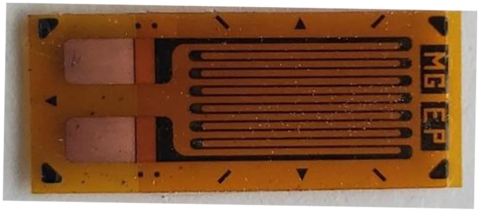
A rosette strain gauge shown in Figure 3 contains three strain grids positioned at known angles such as 45°, 0°, and −45° off the centerline of the gauge. With three measurements, the maximum and minimum strains can be calculated regardless of the orientation at which the gauge is mounted. However, three separate measurement channels are needed to record strains at these known angles.

Rosette strain gauge that contains three strain grids.
Almost all scenarios in real-world applications involve loading along multiple axes. However, loads on cross sections of a slender beam are usually approximated as uniaxial loads on it, due to costs of more transducers needed to measure strains at multiple points of the beam and multiple angles of strain grids. Patent 6,295,878 was issued as a configuration of six strain gauges and six strain grids to measure loading along three axes. 10 Patent 6,354,155 allows for measurement of the force and moment along each of the three axes; 11 however, 12 strain gauges and an equal number of strain grids are needed for this setup. Patent 9,772,237 calculates the magnitude and position of a load with the use of several strain gauges. 12 A multifunctional sensor network using 27 rosette strain gauges was previously developed. 13
This work intends to develop and test a new methodology for a combined loading transducer that uses the minimum numbers of strain gauges, strain grids, and measurement channels to calculate the bending moment and torque in a slender circular beam under combined loading from measured strains in it. A single-rosette strain gauge, two strain grids oriented at 45° from the centerline of the gauge that is aligned with that of the beam, and two measurement channels are used. An advantage of the combined loading transducer is that one can calculate two variables, that is, the bending moment and torque in the beam, using strain measurements from only two strain grids and two measurement channels, which are the minimum possible numbers.
The rest of this article is organized as follows: derivation of the theoretical methodology is developed in section “Theoretical methodology” to minimize numbers of strain gauges, strain grids, and measurement channels. An experimental setup is constructed and calibrated in section “Experimental calibration.” Once calibrated, three different combined loading scenarios are tested: the scenario with an increasing bending moment and torque at the same rate is presented in section “Moment and torque that were increased at equal rates,” that with a constant bending moment and an increasing torque is presented in section “Moment held constant while the torque was increased,” and that with a constant torque and an increasing bending moment is shown in section “Moment was increased while the torque was held constant.” Finally, conclusions are presented in section “Conclusion.”
Theoretical methodology
Consider a cantilever beam with a loading arm, at the end of which a transverse force F is applied, as shown in Figure 4. The bending moment

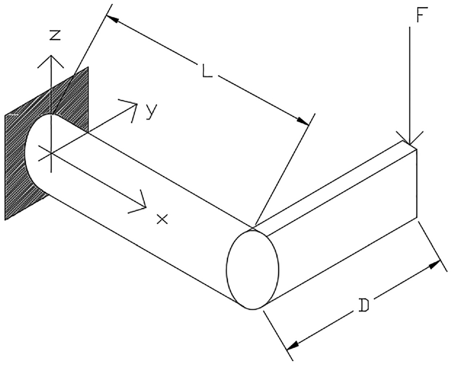
Cantilever beam with a loading arm at the end of which a transverse force F is applied.
The torque

where D is the length of the loading arm.
When the beam is slender with linear, elastic, and isotropic material, the bending stress

where

where

Stress element that contains the normal stress
A rosette strain gauge is used in this work to measure strains at the fixed boundary of the beam and calculate the bending moment and torque on it. The strain


where E is Young’s modulus of the beam,
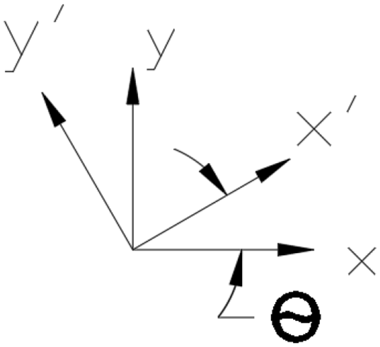
Rotation of the x-y coordinate system in Figure 3 by the angle
From the normal bending stress and the torsional shear stress calculated in equations (3) and (4), respectively, a stress tensor

where

can be used to calculate the rotated normal stress tensor

Due to orientations of the strain grids, desired strains here are for a plane that is rotated

where


Since there is no stress applied in the y-axis, one has

Therefore

Substituting equations (15) and (16) into equations (5) and (6), respectively, yields


Adding equations (17) and (18) yields
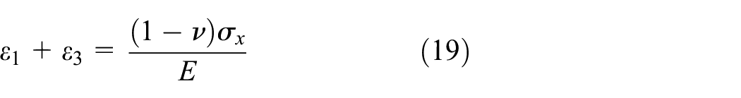
Applying equation (3) to equation (19) yields

A linear calibration constant can be used to connect the applied moment and measured strains. The calibration factor for moment is defined by

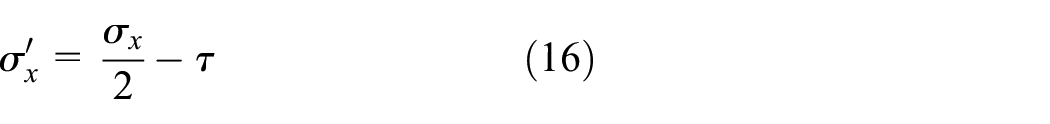
Applying equations (21) to (20) yields

Subtracting equation (18) from equation (17) yields

Applying equation (4) to equation (23) yields

Similarly, a linear calibration constant can be used to connect the torque and measured strains. The calibration factor for the torque is defined by

Applying equation (25) to equation (24) yields

Experimental investigation
An experiment is conducted on a 31.75 mm outer diameter, 1.59 mm wall thickness, aluminum 6061-T6 round tubing. It is secured on one end to a workbench in a cantilever configuration with a fixed boundary condition, via a fillet weld, and the other end of the round tubing has a loading arm to apply torsional and bending loadings, as shown in Figure 7. The length of each end of the loading arm was 29.53 cm, and the length of the cantilever beam is also 29.53 cm. The rosette strain gauge was positioned at 28.58 mm from the fixed boundary, as can be seen in Figure 8. Consistent with the theory in section “Theoretical methodology,”
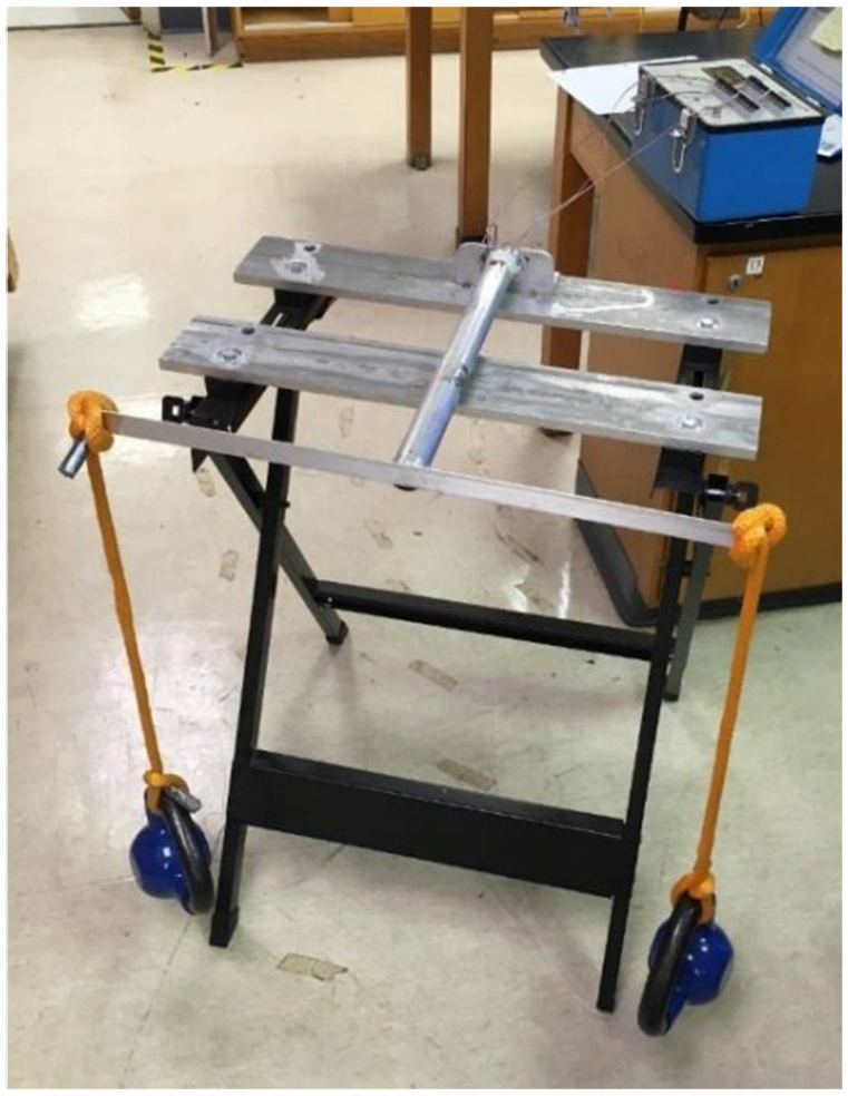
Experimental setup.

Strain gauge located on the cantilever beam.
Experimental calibration
The first set of experiments was used to calibrate the combined loading transducer. The goal was to find
Moment calibration consisted of two equal weights hanging equidistant from the center of the cantilever beam, as shown in Figure 7. Therefore, positive and negative torques created cancel out and only a moment remains. From experimental data, the applied moment is compared to the sum of measured strains
Calibration of moment.
Torque calibration was conducted next by hanging a weight on only one side of the loading cantilever beam, as can be seen in Figure 10. A support block was then installed under the center of the cantilever beam to cancel any moment, as shown in Figure 11. Similarly,

Torque test setup.

Support block.
From experimental data, the applied torque is compared to the difference of measured strains

Calibration of torque.
Moment and torque that were increased at equal rates
The first experiment had the torque and moment that were increased at equal rates, which is a combined loading scenario. This was done by hanging a weight to only the left or right side of the loading beam. A weight on the left side of the loading beam can be seen in Figure 13. Measured values of the weight can be seen in Table 1 and calculated values in Table 2.

Combined loading test setup.
Measured values of the weight from combined loading test with equal moment and torque increments.

Calculated values of the weight from combined loading test with equal moment and torque increments.

From calculated combined loading data, the maximum error in the moment measurements was seen to be 2.9% compared to the theoretical values from equation (1) and the error in the torque was 5.4% compared to the theoretical values from equation (2). These are both reasonably low for the experimental setup.
Moment held constant while the torque was increased
The second experiment was also a combined loading scenario; however, this time the moment was held constant while the torque was increased. This was accomplished by using a single weight of 133 N and varying the distance from the weight to the center on the loading arm, which is similar to what can be seen in Figure 10. Measured values of the weight can be seen in Table 3 and calculated values in Table 4.
Measured values of the weight from combined loading test with the moment held constant and the varying torque.

Calculated values of the weight from combined loading test with the moment held constant and the varying torque.

The maximum error between the measured moment calculated from equation (22) and the theoretical moment was 3.2%. The maximum error between the measured torque from the torsional stress calculated from equation (26) and the theoretical torque was 14.1%.
Moment was increased while the torque was held constant
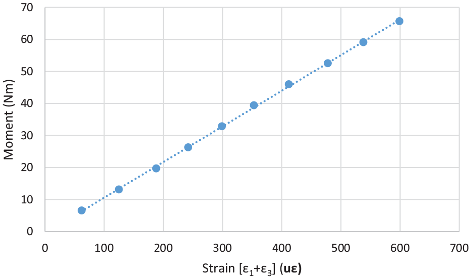
The final experiment was a combined loading scenario where the torque was held constant while the moment was increased. This was accomplished using different weights to create different moments, which is similar to what can be seen in Figure 10. The distance from the weight required to the center of the cantilever beam was then calculated to maintain a constant torque. Measured values of the weight can be seen in Table 5 and calculated values in Table 6.
Measured values of the weight from combined loading test with the torque held constant and the varying moment.

Calculated values of the weight for combined loading test with the torque held constant and the varying moment.
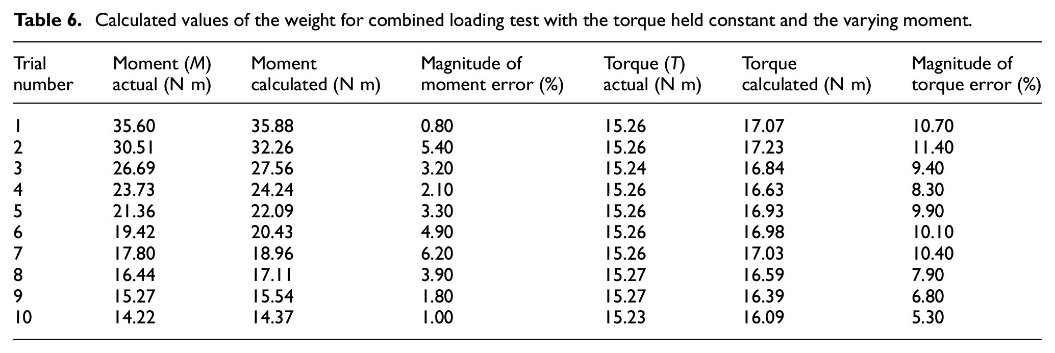
From calculated combined loading data, the maximum error in the moment measurements was seen to be 6.2% and the error in the torque was 11.4%. These are both reasonably low for the experimental setup.
Conclusion
The experiments in this work have proven the methodology of the combined loading transducer. Only one strain gauge, two measurement channels, and two strain grids were needed to independently measure the moment and torque. Two strain grids of a single-rosette strain gauge were used to accurately calculate the moment from the bending stress and the torque from the torsional shear stress in the combined loading scenarios. Calibration factors were independently found from loading tests of the moment and torque and used throughout other combined loading scenarios.
The moment had an average magnitude error of 1.6% over the three combined loading scenarios. The torque error was higher at 6.7% mainly due to the system calibration and setup. It is also possible that there was some deflection with the support system at the boundary, allowing for an unaccounted moment in the torque test. While in theory, the cantilever beam is connected to an immovable boundary, in practice there could have been a small deflection at the boundary.
Footnotes
Appendix 1
Handling Editor: James Brusey
Declaration of conflicting interests
The author(s) declared no potential conflicts of interest with respect to the research, authorship, and/or publication of this article.
Funding
The author(s) received no financial support for the research, authorship, and/or publication of this article.