
Abstract
The unmanned aerial vehicle features with high flexibility and easy deployment. It could be used as an air base station and provide fast communication services for the ground users. It plays an important role in some special occasions such as natural disasters, emergency communications and temporary large-scale activities. A single unmanned aerial vehicle equipped with base station has limited range of services, but a multiple unmanned aerial vehicle equipped with base station network can serve a wider range of users. The research goal of unmanned aerial vehicle equipped with base station network coverage control is to maximize the network coverage under the condition of maintaining the service quality. In view of the low dynamic coverage ratio of unmanned aerial vehicle equipped with base station network, this article proposes a relative distance–based unmanned aerial vehicle equipped with base station deployment method. The unmanned aerial vehicle realizes on-demand coverage and maintains a stable network topology under the influence of three relative distances by sensing the uncovered area of the ground, the neighbouring unmanned aerial vehicles and the location of the coverage boundary or obstacles. In addition, the algorithm is also adapted to a variety of scenarios. The simulation results show that the coverage of the proposed algorithm is 22.4% higher than that of random deployment, and it is 9.9%, 4.7% and 2.1% higher than similar virtual force-oriented node, circular binary segmentation and hybrid local virtual force algorithms.
Introduction
When a disaster happens, fixed base station may be destroyed by a flood, earthquake or tsunami, thereby causing disruption in the wireless network. This may hinder rescue operations. In temporary large-scale events, the limited capacity of nearby fixed base stations may result in slowness of Internet access or no available network. It is unlikely and costly to build the infrastructure immediately under these circumstances. As air base stations, unmanned aerial vehicles equipped with base stations (UAV-BSs) can provide large coverage for ground users and have broad application prospects in temporary large-scale activities, earthquake relief and emergency communications.1–3 The mobile UAVs can be quickly networked based on the real-time needs and provide communication service for ground users in these special occasions so that users on the ground that cannot communicate directly can implement multi-hop communication through the UAV network. 4 In addition, environmental monitoring is also one of the important uses of UAV-BS network. UAVs can overcome inconvenient traffic, dangerous conditions and other adverse factors, and can be quickly deployed over the task area to check the environment of the task area. UAV monitoring has been used in wildlife environment, dangerous ocean and other areas.5–7
Due to the high dynamics of UAV-BS network and the complex environment, there are still many technical challenges in the research of deployment coverage. First of all, unlike ground base stations, the path loss of a UAV-BS is determined by the user and the location of the UAV. Second, the deployment of a UAV-BS is a three-dimensional (3D) problem with nonlinear constraints. In addition, the current UAV-BSs are mostly battery-powered and have limited operating time. Therefore, it is particularly necessary to study a method that covers the task area quickly and efficiently on the premise of adapting to a variety of scenarios and meeting the quality of service (QoS) of the user.
In this article, aiming at full coverage of the task area, a local optimization algorithm for deploying a UAV-BS network based on relative distance (RD) is proposed. To ensure the QoS and improve coverage, under the influence of three types of RDs, the UAV-BS completes the re-deployment of UAV-BSs after random deployment and network coverage could be improved.
The rest of this article is organized as follows: Section ‘Related work’ discusses some works that is relevant for the deployment of UAV-BSs. Section ‘System model’ introduces the system model and the calculation method of coverage ratio. Section ‘Introduction of the UAV-BS deployment algorithm–based RD’ discusses the coverage algorithm of UAV-BSs based on RD, analyses the factors affecting the motion of UAV-BS and describes the algorithm process. Section ‘Simulation and result analysis’ analyses the effectiveness of the proposed optimization algorithm through experiments and data comparisons. Finally, the last section provides conclusions.
Related work
It is also very important to study the deployment of a single UAV before studying the deployment of a UAV-BS network. M Mozaffari et al. 8 considered the impact of single UAV’s height and coverage radius on deployment performance under the air-to-ground channel model. M Alzenad et al. 9 proposed a 3D layout of a single UAV-BS, maximizing the number of users being covered with minimal transmission power. E Kalantari et al. 10 obtained an optimal position of a single UAV-BS by performing an exhaustive search in a predefined grid.
The research on UAV-BS network deployment coverage has become a research hotspot in recent years. The existing UAV base station planning methods generally only consider static base station deployment and basically do not involve dynamic planning. H Ghazzai et al. 11 used the meta-heuristic algorithm to obtain the position of the minimum number of UAV-BSs that meet the system constraints, but the height and specific coverage of the UAV are not discussed. M Mozaffari et al. 12 proposed a deployment method based on the circular coverage theory, which maximizes the coverage of each UAV and minimizes the transmit power, but it is not general to think the total coverage area as a circle. E Kalantari et al. 13 proposed a heuristic algorithm based on particle swarm optimization to get the number and 3D positions of UAV-BSs that met the system’s required coverage requirements and capacity constraints. M Mozaffari et al. 14 proposed a gradient-based geographic region optimal partitioning algorithm when considering user distribution, flight time and locations of UAVs, but did not indicate the coverage of the UAV. J Lyu et al. 15 proposed a spiral algorithm to obtain the minimum number of UAV base stations required to cover all users. B Galkin et al. 16 used the K-means clustering method to deploy a UAV-BS to assist the ground base station. Z Haitao et al. 17 implement on-demand coverage for a given user distribution, and the UAV-BS can change the corresponding position as the user moves while maintaining the interconnection between the UAVs. L Tan et al. 18 proposed the maximum coverage of the UAV network based on virtual force for a hotspot. They used the virtual force to guide the UAV group to track the target of real-time motion in the three-dimensional space, but they did not reach the connectivity requirements of the UAV. Chen et al. 19 proposed an improved multi-population genetic algorithm to maximize the number of users covered by different service quality requirements. Lai et al. 20 and Alzenad et al. 21 have all proposed to maximize the number of users covered while meeting the data rate required by each user. Kalantari et al. 13 proposed a heuristic algorithm based on particle swarm optimization to suboptimally find the minimum number of UAV base stations serving a specific area and their locations. Although a suboptimal solution was found, the search speed was relatively slow, and communication between UAVs was not considered. The above methods assumed that the number and location distribution of ground users are known and stationary, to minimize the number of drones or maximize the number of users covered. However, when a disaster occurs, the ground user’s location information cannot be obtained immediately, the number and locations of ground users are generally unknown, and the user’s location also changes in real time. To guarantee service, UAV-BSs are required to adjust their own positions to track users. At this time, as long as the UAV-BS network completely covers the task area, it can serve all users in the task area without following the user’s movement, and it can also monitor the ground situation in all directions.
System model
Scene description
For the ground area to be covered, a plurality of UAVs – UAV1, UAV2, …, UAV n – are given to realize on-demand coverage communication to the ground task area. For the UAV, the location of the covered area is known, and its own location information is passed by global positioning system (GPS) devices that are available in real time. In the work by Alzenad et al., 9 the optimal height of a UAV in achieving maximum coverage is discussed. In this article, all UAVs are set to hover at the same height to cover ground users. The user distribution is uniform, regardless of other user distribution modes. When all areas are completely covered, all users in this area can be connected by UAV-BSs, as shown in Figure 1.

UAV-BS coverage network model.
Air-to-ground channel model
The air-to-ground channel model is introduced for the communication between the UAV-BS and the ground users. Unlike the ground base station, the radio signal sent by the UAV-BS in the air-to-ground channel model communicates with the user through two paths: one is line-of-sight (LoS) communication or approximate LoS communication, in which the signal reaches the user directly; the other is non-line-of-sight (NLoS) communication, in which the signal is strongly reflected or diffracted and then reaches the user. This article uses the channel model which has been commonly used in Mozaffari et al. 8 The two propagation paths have corresponding propagation probabilities P(LoS) and P(NLoS), respectively
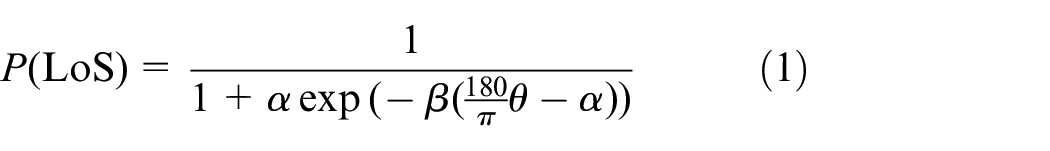

where α and β are constant depending on the environment (rural, urban, dense city, etc.), and
The radio signals from the UAV-BS propagate in free space until they reach the ground users. In the urban environment, the buildings and other artificial buildings cause shadows and scattering, which bring additional losses to the air-to-ground link. The path loss is generally caused by free space path loss and additional loss caused by reflections such as buildings. When LoS transmission and NLoS transmission occur, the average path loss is


where

That is

If the transmit power of UAV-BS is Pt, the received power Pr is

To guarantee the QoS of the user, it is assumed that the received power Pr must exceed a certain threshold Pmin. This is equivalent to the path loss experienced by the UAV to any user i which must be less than or equal to a certain threshold PLth to guarantee communication. When the path loss between the UAV-BS and the ground user i exceeds this threshold, the link is broken. This threshold corresponds to the radius area that a UAV-BS can serve, since all path losses in this radius area are less than this threshold. There is an optimal elevation angle in different environments, which can make the UAV cover the largest radius, and the corresponding height is the optimal height of the UAV. The best elevations for suburban, urban, dense urban and high-rise urban are 20.34°, 42.44°, 54.62° and 75.52°, respectively. The simulation environment selected in this article is urban.
Coverage indication
It is assumed that k UAV-BSs are randomly deployed in the air of the monitoring area in the initial stage of deployment. The coverage radius of each UAV-BS is R. When the distance between any ground user in the task area and the ground projection point of the UAV-BS is less than the coverage radius, the probability that the ground user is covered is 1, that is, with the ground projection point of the UAV-BS as the centre, all points in the circular range with radius R can be completely covered by the UAV-BS. The load capacity of the UAV-BS is ignored in this article. Assume that the projection position of the UAV
i
is

The area coverage calculation method used in this article is proposed by Gage et al. 22 and its definition is as shown in equation (9). The task area is divided into a series of grids of equal length, each grid being a sub-area. The smaller the side length of each sub-area, the more accurate the coverage calculation. If a large area of a sub-area is covered by at least one UAV-BS, the sub-area is considered to be covered. The criterion for whether most of the sub-areas are covered is determined by whether the centre point of the sub-area is covered. Coverage ratio can be expressed as the ratio of the sum of the coverage of all UAV-BSs and the sum of the sub-areas that all UAV-BSs need to cover
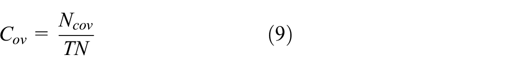
where Cov represents the coverage ratio, Ncov represents the number of sub-areas that have been covered and TN represents the total number of sub-areas in the task area.
Assumptions
The UAV-BSs can move freely in the air and spontaneously move to suitable locations to form a network, thereby achieving on-demand coverage of the ground. For the convenience of analysis, the following assumptions are made for the network of UAV-BSs:
This article specifies that the UAV-BS can communicate with other UAV-BSs in the communication radius rc, can sense the presence of the ground user within the radius rs and can establish a link with the user within the coverage radius R, where rc = rs = 2R; the coverage radius R can be adjusted to achieve multi-scene, multi-environment coverage on demand.
The UAV-BS is equipped with a GPS module and knows its own position information.
The information of ground area which needs to be covered is known for the UAV-BSs.
Introduction of the UAV-BS deployment algorithm–based RD
Basic idea
The basic idea of the deployment algorithm–based RD is to take the full coverage as the goal and divide the task area into several grids to be covered, and then the UAV-BSs will move under the influence of the RD from the uncovered grids to reduce the number of uncovered grids as much as possible. During this period, the distance between the UAVs may be so close to cause collision or overlapping coverage. For this reason, the RD between the UAV-BSs is introduced, and when the distance is less than a threshold distance, the UAVs are far away from each other. To prevent the UAV from flying out of the boundary or entering the obstacle area, the UAV must fly within allowed area under the influence of RD. Under the influence of three RDs, the UAV completes the re-deployment of UAV-BSs after random deployment and network coverage could be improved.
Problem formulation
In the deployment algorithm of this article, the motion of each UAV-BS is affected by three kinds of RDs: RD of uncovered mesh and UAV, RD between UAVs and RD between task area boundary or obstacle and UAVs. Assume that all RD vectors weighted by the UAV i are di: the RD between the UAV i and the UAV j is dij; the RD between the uncovered grid and the UAV i is dig; and the RD between the boundary or obstacle and the UAV i is dib. Therefore, the RD vector sum acting on the UAV i is

RD between uncovered area grid and UAV
The key factor affecting the mobility of UAVs is the RD between the uncovered grid within the sensing range and the UAVs. First, divide the task area into a series of grids with equal lengths of sides and get the total number of grids and the coordinates of the centre point of these grids. When the distance between the uncovered grid and the UAV is greater than the coverage radius R and less than the sense radius rs, the UAV moves in the direction of the uncovered grid. The distance between the UAV and the uncovered grid is shown in Figure 2.

The distance between the UAV and the uncovered grid.
dig is used to indicate the distance between the uncovered grid and the UAV, and dig can be decomposed into the distance vector digx in the x-axis direction and the distance vector digy in the y-axis direction. The RD expression of the uncovered grid and the UAV is as shown in equation (11)

The UAV will move under this type of RD, and the updated position is

where Max_grid is the maximum step size of the UAV movement under the influence of the RD between the UAV and the uncovered grid. To reduce the instability of the algorithm in the later stage, when the distance between the UAV and the uncovered grid is less than the maximum step size Max_grid, the moving length is the distance between the drone and the grid point

RD between UAVs
There is an RD between each UAV and the neighbour UAV. If the distance between the two UAV-BSs is less than a pre-set threshold, the UAV moves in a direction away from the neighbour UAV. This is to ensure that the UAV does not over-collect in an area and repeat coverage of an area. If the distance between two UAVs is greater than the threshold, the RD between the two UAVs will not affect the movement of the UAV. Figure 3 shows two ways of deploying three UAV-BSs. With the deployment method of Figure 3(a), the coverage area of the UAV-BSs partially overlaps, but there is no blind area. With the deployment method of Figure 3(b), there is no overlap in the coverage area of the UAV-BSs, but there is a coverage blind area in the middle. If we want to cover this blind area, we need to add a UAV-BS. In this article, the UAV is deployed as shown in Figure 3(a), and the threshold is calculated as

Two different coverage styles: (a) hole-free coverage and (b) overlap-free coverage.
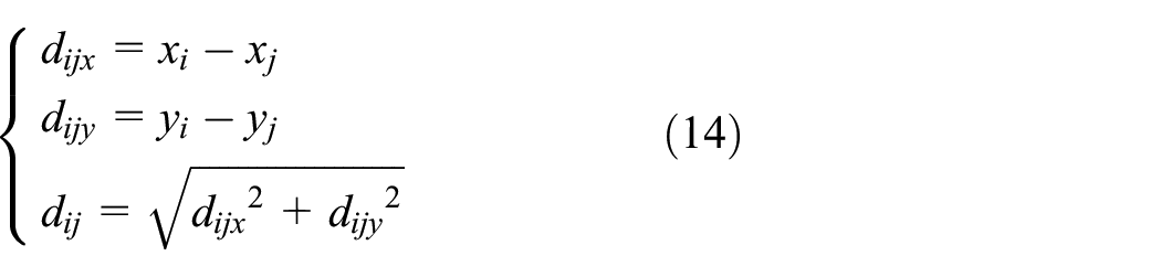
The RD dij between the UAV i and UAV j is decomposed into a distance vector dijx in the x-axis direction and a distance vector dijy in the y-axis direction, and the RD expression between the UAVs is as shown in equation (14)
When the distance between the UAVs is less than the threshold, the UAV will move under the RD, and the updated position is
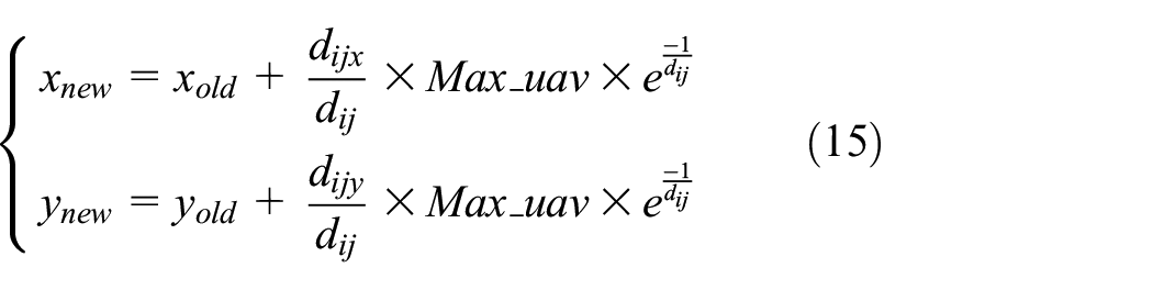
where
RD between obstacles or borders and UAVs
In the actual environment, there may be obstacles in the task area of the UAV-BSs, and there is also a distance between the UAV and the obstacle, which will be far away from the obstacle under the influence of this distance; to prevent the UAV-BS from exceeding the boundary for invalid coverage, the UAV-BS position adjustment is also required under the constraints of the boundary. When the UAV-BS exceeds the boundary, the UAV-BS moves in the direction of the inside of the boundary. The UAV position update is similar to that of equations (11) and (12).
Motion control algorithm
According to Newton’s second law of motion, the change in velocity dt in seconds is governed by the resultant force acting on UAV-BS i, and that is

where mi is the mass of the UAV-BS i and is normalized as 1 in this research and ai is the acceleration of UAV-BS. We use the RD to represent the resultant force because the concept of force is not covered in this research.
The motion velocity of the UAV-BS i is

In the same time interval, the moving distance di of the node is proportional to the value of the acceleration ai

From equations (16) and (17), it is known that when the RD needs to move between the UAV-BS and the uncovered grid, the higher the speed. However, in practical applications, the motion velocity of each UAV-BS has a maximum velocity limit, and the velocity value vi is usually constant

In each iteration, UAV-BS i computes the RD according to equations (11) and (14) and then changes its location according to the velocity. Specifically, this motion control is done in three stages as below:
Initialization: Each UAV-BS is informed about the information of task area, such as the size and border.
Motion control: Motion control is performed iteratively. In each iteration, any UAV-BS (assuming UAV-BS i) senses uncovered grids and obstacles with known information, calculates RD and velocity, and broadcasts a message containing its location information. Its one-hop neighbour can receive this message to obtain the location information of UAV i . Similarly, UAV i can obtain the location information of all its one-hop neighbours, calculating distance and velocity. Repeat the above steps until the stop condition is met (see below).
Stop condition: If the task area is fully covered, the motion will stop in ideal condition. But it may take a large number of iterations. We therefore specify that UAV i stops moving when the following two conditions are satisfied: (a) the coverage ratio meets the target, and (b) the number of iterations meets maximal.
The detailed motion control algorithm flow for UAV-BS i is given in Figure 4.

Algorithm flowchart.
Simulation and result analysis
In this article, MATLAB 2018a is used to simulate the distributed UAV-BS deployment algorithm. The main simulation parameters are listed in Table 1. To test the universality of the algorithm, the algorithm is verified according to three different scenarios.
Primary simulation parameters.

UAV: unmanned aerial vehicle.
Scene 1: when there are no fixed base stations in the task area, 49 UAVs are randomly deployed
The reason for choosing 49 UAVs is that when using the cellular grid to fully cover the ground, 49 cellular grids with a side length of 100 m just cover this task area completely. Figure 5(a) depicts the initial deployment state of UAVs. At this time, the UAVs are randomly distributed, and it can be seen that a large area of the ground is not covered. Figure 5(b) shows the algorithm iterating 10 times, and the UAVs start moving because of three RDs. The red dots in Figure 5(c) represent the initial positions of the UAV, the lines represent the motion tracks of the UAVs, and the UAVs move to the uncovered area. Figure 5(d) shows the final deployment of the UAVs, with the task area reaching almost full coverage.
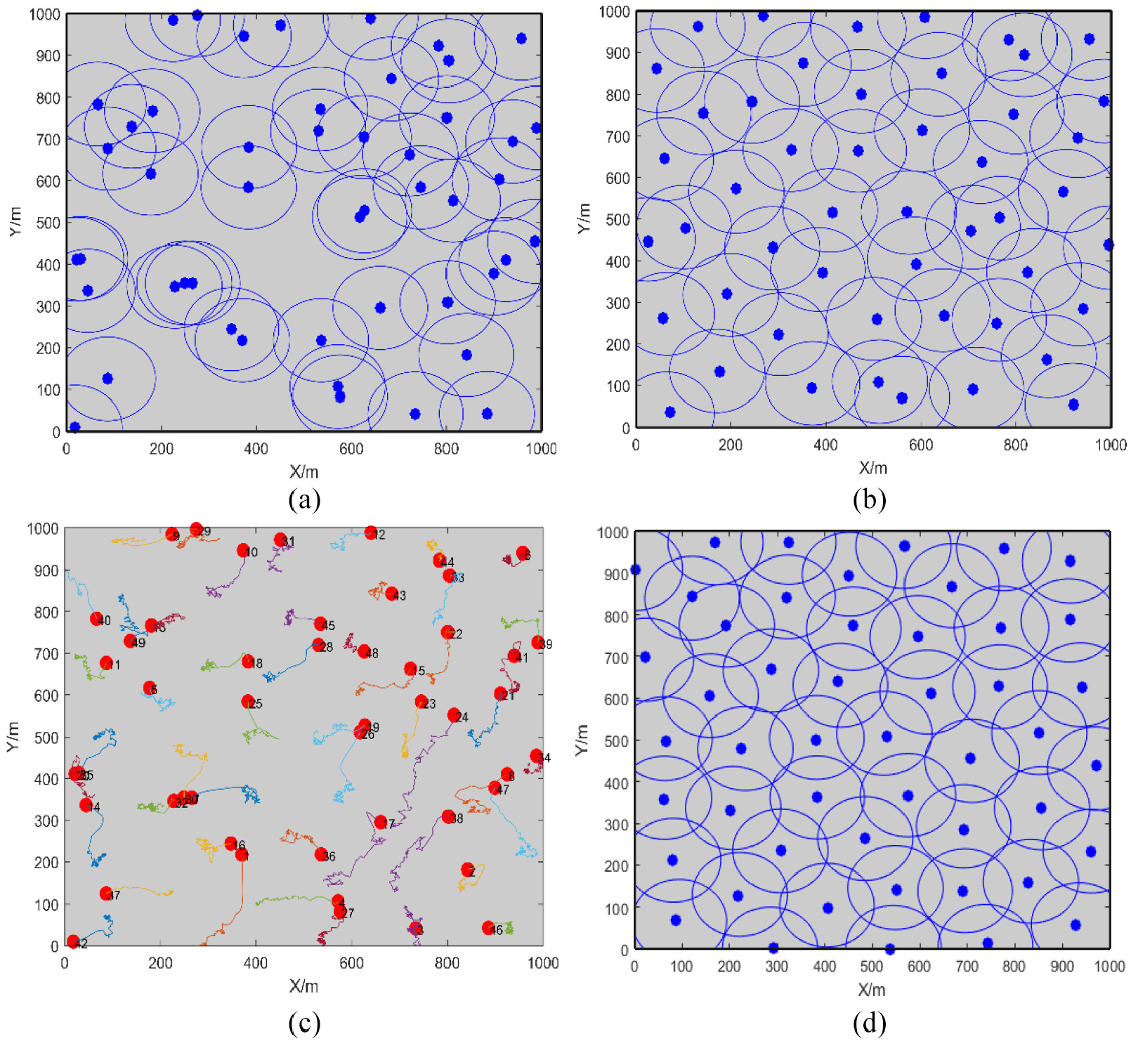
UAV-BS dynamic deployment process: (a) initial state, (b) iteration = 10, (c) movement track of UAVs and(d) iteration = 101.
Figure 6 depicts the impact of the UAV-BS network on the coverage of the task area at different coverage radii when deploying 40 UAVs. It can be seen that when the coverage radius of the UAV is fixed, the network coverage increases first with the increase in iterations. After the increase, it tends to be stable. When the number of iterations is constant, the coverage radius of the UAV is higher, and the network coverage is higher. When the UAV coverage radius is increased to 120 m, the network coverage can be increased by 100% with the increase in iterations. Since coverage is up to 100%, coverage will not continue to increase as the UAV coverage radius continues to increase. The UAV coverage radius is determined by the UAV’s transmit power and path loss threshold. When the path loss threshold is constant, the power is stronger and the UAV coverage radius is larger. Increasing power raises system energy consumption and reduces network life. Therefore, it is necessary to consider the coverage ratio and system energy consumption when selecting the appropriate radius.

The influence of the coverage radius on the coverage ratio.
Figure 7 simulates the effect of different coverage radii and the number of UAV-BSs on the average convergence time of the algorithm when the coverage radius R is 100 m. It can be seen that as the number of UAVs increases, the average convergence time required by the algorithm is shorter; the average convergence time required for different coverage radii is also different; when the number of UAVs is the same, the larger the radius and the shorter the required convergence time. This is because the larger the number of UAV and the larger the radius of UAV, the higher the coverage ratio in the initial state of the UAV network and the lesser the uncovered area. Therefore, the number of iterations of the algorithm is small, which tends to make the algorithm reach convergence quickly.

The influence of the number and coverage radius of UAVs on the average convergence time.
Scene 2: when there are some mooring UAVs in the task area
When the UAV-BSs are actually deployed, there may be some mooring UAVs, that is, there is no need to move UAV to cover within the coverage of the mooring UAVs. In this scenario, when the mooring UAV N1 = 3 is simulated, the mobile UAVs are four cases of N2 (30, 35, 40 and 45). Figure 8 depicts the coverage of an example of three mooring UAVs and 40 mobile UAVs. It can be seen from Figure 8 that the mobile UAVs are first dispersed according to the RD between the UAVs and away from the area covered by the mooring UAVs to cover the remaining area and maximize the other coverage areas.

UAV deployment in the presence of mooring UAVs: (a) initial state, (b) movement track of UAVs and (c) iteration = 101.
Figure 9 depicts four coverage ratio changes for 30, 35, 40, and 45 mobile UAVs with three mooring UAVs, respectively, with coverage rates of 84.9%, 89.2%, 94.1%, and 97.6%, respectively. The number of iterations required to achieve stable coverage is 55, 30, 20, and 18 times, respectively. It can be seen that the greater the number of mobile drones, the higher the coverage rate and the fewer the iterations required to achieve stable coverage. This is because the number of drones increases, the initial coverage is large, the areas that are not covered are small and the number of iterations required for the coverage to reach a steady state is reduced.

Coverage ratio changes in three mooring UAVs and different numbers of mobile UAVs.
There are obstacles or electronic fences in the coverage area
When the UAV-BSs are deployed in the actual mission area, in addition to encountering obstacles, it may also include electronic fences. For example, a certain area is controlled by the military. Civil UAVs are not allowed to fly over the electronic fence. We have also simulated the existence of electronic fences, because they are similar to the simulation scene of obstacles, which are hereinafter referred to as obstacles. Figure 10 simulates the deployment of UAVs when there are obstacles in the coverage area. Three obstacles (white circles) are set in the task area. In the actual scene, the height of the obstacle is much higher than the height of the UAV, so the UAV cannot fly into the obstacle area. Under the action of the distance between the drone and the obstacle, the drone flies away from the obstacle and covers the remaining area. Figure 10(a) shows the initial deployment position of 40 UAVs when there are three obstacles. Figure 10(c) shows the coverage of the UAVs to the final deployment. It can be seen that the UAVs do not move to the obstacle area and the coverage is achieved.

UAV deployment in the presence of obstacles: (a) initial state, (b) movement track of UAVs and (c) iteration = 101.
Comparison of performance of different algorithms
Due to the full coverage of the ground considered in this article without considering the specific distribution and location of ground users, it cannot be compared with the recent algorithms. However, in this article, the superiority of the RD algorithm is proved, and the algorithm is compared with similar virtual force-oriented node (VFON) algorithm, 23 circular binary segmentation (CBS) algorithm 24 and hybrid local virtual force algorithm (HLVFA). 25 Figure 11(a) and (b) shows the effect of iterations and the number of drone base stations on the network coverage performance of the four algorithms. It can be seen in Figure 11(a) that the RD algorithm does not converge at the fastest speed. This is because there are many grids to divide the ground area, and the algorithm needs a long time to traverse, but the stable coverage is the highest. Figure 11(b) shows that the coverage ratio of the four algorithms is increasing as the number of UAV base stations increases, and the RD algorithm has the highest network coverage ratio.
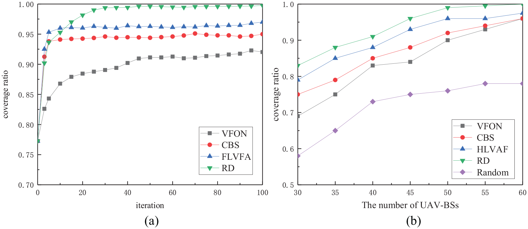
Comparison of performance of different algorithms: (a) change in the coverage ratio and (b) change in the coverage ratio with different numbers of UAVs.
Conclusion
This article proposes an RD-based UAV-BS deployment method. The movement of the UAVs does not require central control, and they are only affected by three types of RDs. It is self-organized to form a UAV-BS network, which realizes communication between UAVs while meeting the QoS, and the coverage area is maximized. The simulation proves that the algorithm can be adapted to three scenarios and achieves high coverage ratio. UAV-BS network is a complex network optimization problem. In the next step, the load balancing of the UAV base station network will be further studied.
Footnotes
Acknowledgements
We also would like to thank the anonymous reviewers for their comprehensive reviews and comprehensive feedback.
Handling Editor: Daniel Gutierrez-Reina
Declaration of conflicting interests
The author(s) declared no potential conflicts of interest with respect to the research, authorship, and/or publication of this article.
Funding
The author(s) disclosed receipt of the following financial support for the research, authorship, and/or publication of this article: This work was supported by The Xi’an Science Project (No. CXY1835 (4)) and The Shaanxi Key Industry Chain Innovation Project (No. 2017ZDCXL-GY-05-03).