
Abstract
In this article, three novel systems for wireless sensor networks based on Alamouti decoding were investigated and then compared, which are Alamouti space–time block coding multiple-input single-output/multiple-input multiple-output multicarrier modulation (MCM) system, extended orthogonal space–time block coding multiple-input single-output MCM system, and multiple-input multiple-output system. Moreover, the proposed work is applied over multiple-input multiple-output systems rather than the conventional single-antenna orthogonal chirp division multiplexing systems, based on the discrete fractional cosine transform orthogonal chirp division multiplexing system to mitigate the effect of frequency-selective and time-varying channels, using low-complexity equalizers, specifically by ignoring the intercarrier interference coming from faraway subcarriers and using the LSMR iteration algorithm to decrease the equalization complexity, mainly with long orthogonal chirp division multiplexing symbols, such as the TV symbols. The block diagrams for the proposed systems are provided to simplify the theoretical analysis by making it easier to follow. Simulation results confirm that the proposed multiple-input multiple-output and multiple-input single-output orthogonal chirp division multiplexing systems outperform the conventional multiple-input multiple-output and multiple-input single-output orthogonal frequency division multiplexing systems. Finally, the results show that orthogonal chirp division multiplexing exhibited a better channel energy behavior than classical orthogonal frequency division multiplexing, thus improving the system performance and allowing the system to decrease the equalization complexity.
Keywords
Introduction
Previously, the single-input single-output (SISO) orthogonal frequency division multiplexing (OFDM) and orthogonal chirp division multiplexing (OCDM) systems based on discrete fractional Fourier transform (DFrFT) and discrete fractional cosine transform (DFrCT) were investigated carefully under the doubly dispersive channel scenario in previous studies.1–5 It was found that OCDM systems outperform the OFDM systems that the OCDM systems can cope perfectly with the doubly dispersive channel variations. Roughly speaking, the OCDM subchannel carrier frequencies are time-varying and ideally decompose the frequency distortion of the channel perfectly at any instant in time as the OCDM chirp bases match the essential time-varying characteristics of the doubly dispersive channel. 6
Currently, there is a great demand on higher data throughput with a limited bandwidth that is facilitated using multiple-input multiple-output (MIMO) systems. MIMO is one of the several forms of smart antenna technologies which improve the communication performance using more than one antenna at the transmitter and the receiver. A popular approach in MIMO systems is to combine it with multicarrier methods such as OFDM to improve the overall system performance which is known as MIMO-OFDM.
A primary example of MIMO-OFDM is the multiple-input single-output (MISO) Alamouti space–time block coding (STBC) and the MISO extended orthogonal space–time block coding (EO-STBC) combined with the OFDM system to achieve locative and multipath variety gains and to decrease the intercarrier interference (ICI) error level. Nevertheless, under high-speed movement of the transmitter, receiver, or both; applying the Alamouti STBC or the EO-STBC over nearby OFDM symbols is regarded as not successful due to the major channel time disparity.
In this article, three novel systems are introduced which are Alamouti STBC MISO multicarrier modulation (MCM) system, EO-STBC MISO MCM system, and MIMO system, based on the OCDM MCM systems which are shown to improve these systems’ performance under the doubly dispersive channel scenario. In addition, MIMO systems are investigated in this article, together with the Alamouti STBC MISO system, the EO-STBC MISO system, and the MIMO system accompanied with the OCDM MCM systems. The explanation of the key implementation of the transceiver is provided to make the full picture of the suggested work clearer. The system’s equalization problem is stated in this work and a comparison between complicated equalizers and low-complexity equalizers is made.
MIMO systems
The earliest ideas in MIMO belong to the work by Kaye and George 7 and Brandenburg and Wyner. 8 MIMO is one of the most important technologies in wireless communications, as it compromises an increase in the data throughput and the connection range, without requiring an extra bandwidth or a transmission power. MIMO does so by splitting the total power conducted over the system antennas to obtain the gain array, thus improving the spectrum efficiency (more bits per second per hertz of bandwidth), and/or to obtain diversity gain which enhances the link consistency by reducing the fading effect. These properties increased the interest in MIMO to become an important part in the recent wireless communication standards, such as IEEE 802.11 b/g/n Wi-Fi, WiMAX, and 5G.
There are several particular cases of MIMO such as SISO/single-input multiple-output (SIMO)/MISO where SISO is the standard radio arrangement, that is, the transmitter and the receiver each have only one antenna, taking into consideration the fact that the MISO is regarded as a special case when the transmitter has more than one antennas and the receiver has a single antenna, while SIMO is regarded as the special case when the transmitter has one antenna and the receiver has several antennas.
Siavash M Alamouti 9 proposed a simple MISO system using two transmitting antennas and one receiving antenna; this algorithm is called STBC providing a full diversity order. More details about the Alamouti scheme are presented in the next section of this article.
Some innovative diversity systems such as EO-STBC, where degree one and extreme diversity order are accomplished concurrently, regardless of the process with four transmitting antennas, because of the use of extra beam steering that is established on the feedback of channel state information (CSI).10,11
Alamouti STBC and the EO-STBC systems have been produced in the context of narrow-band static channels. In frequency fading channel conditions, an arrangement with multicarrier systems such as OFDM 12 is used, in order to operate narrow-band Alamouti STBC and EO-STBC systems in separate subcarriers, which are clear of intersymbol interference (ISI) and ICI. In the circumstance of narrow-band time-varying systems; the scheme degradation is minimal on condition that the channel disparity over one Alamouti STBC or EO-STBC symbol can be defined as a minor variation. Nevertheless, if a time-varying channel exhibits additional delay spread, then the classical use of multicarrier methods leads to considerably longer symbol periods, which will require the introduction of various equalisation approaches in the frequency domain such as zero-forcing (ZF) and minimum mean square error (MMSE) schemes, 13 or other receivers are to be applied for the individual subcarriers, including the ZF, decision-feedback (DF), and joint maximum-likelihood (JML) detectors,1,2 however, the neglected ICI introduces an error floor on the bit error rate (BER) performance as loss of orthogonality is increased.
In previous studies,3,14–16 the loss of OFDM orthogonality in doubly dispersive channels was studied and multicarrier schemes based on DFrFT and DFrCT were developed that the DFrFT and the DFrCT-OCDM schemes granted better performance in the doubly dispersive channel scenario. Therefore, a novel combination of the DFrFT and DFrCT-OCDM systems with Alamouti and EO-STBC is proposed in the following sections, together with investigating the combination of conventional and low-cost equalization approaches.
Fractional Fourier transform and fractional cosine transform
The fractional Fourier transform (FrFT) is a generalization of the Fourier transform (FT) and can be viewed as the fractional power of the FT operator. In the time–frequency plane, the original signal in the time domain represented by
The transformation kernel of the continuous FrFT is defined as 17
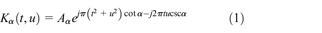
where α is the rotation angle for the transformation process and

The forward FrFT is defined as

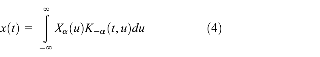
The domains of the signal for
By extension, fractional cosine transform may be considered as a generalization of the discrete cosine transform (DCT), the

where the angle between the fractional order axis
Various definitions of the DFrCT differ in accuracy and complexity and may be derived using extensions from the FrFT by sampling the real/imaginary parts of the FrFT kernel or directly from the DCT itself.
20
The definition of DFrCT in Soo-Chang and Min-Hung
19
is used in our work. It has minimal complexity and a simple inverse transform. In the following, we will denote the DFrCT as
The vector notation for the DFrCT is given by

where Fα is the unitary

where
DFrCT complexity
Implementing the FrFT for a given signal requires two chirp multiplications and one DFT,
20
since an efficient DFT requires approximately

Using similar arguments and by computing the DFrCT from the first-type DCT kernel, 20 the DFrCT requires

Consequently, the complexity of the FrCT is approximately half that of the FrFT.
OCDM Alamouti MISO STBC system
The point-to-point OCDM multicarrier system based on Alamouti’s
9
scheme presented in Paige and Saunders
21
is adapted in this article, and the scheme is implemented using two antennas on the transmitter side and one antenna on the receiver side as shown in Figure 1. It is assumed that the same transmission system of the SISO-OCDM system is used, except that every two consecutive OCDM symbols are considered as an Alamouti code word. Assume that

where

where

The Alamouti coded OCDM system.


where
The DFrCT demodulates the received signal; accordingly, the two successive demodulated received signals are given by


Combining

where

where


(a) Fractional domain doubly dispersive channel matrix with
In equation (17),

where
where

Fractional domain doubly dispersive banded channel matrix

Fractional domain doubly dispersive banded channel matrix after permutation
Low-complexity MMSE equalizer
The low-complexity MMSE equalizers proposed for OFDM in Solyman et al.3,16 will be extended to the MISO Alamouti coding scheme in this section.
Ideal knowledge of the channel matrix
The MMSE equalizer

The estimated data are given by

where

The overall complexity for obtaining
Applying LDL
H
25
matrix factorization in computing MMSE solutions in equation (49) will reduce the number of complex processes related to standard matrix inversion methods, such as Gaussian elimination to
Using the same formulation with the iterative MMSE equalization that applies the least-square minimal residual method iterative algorithm (LSMR) algorithm as in Solyman et al.
3
results in reducing the equalizer complexity to
The

Instead of calculating the inverse in equation (24), the system
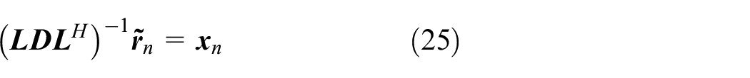


is solved by forward substitution to obtain
The overall complexity for obtaining
Low-complexity LSMR equalization
MMSE equalizer complexity comes from the matrix inversion in equation (21), and solving this matrix inversion iteratively is one of the clever ideas to reduce the MMSE equalizer complexity. In previous studies,26–29 the authors use the iterative LSQR (An algorithm for sparse linear equations and sparse least squares) algorithm,
21
which exhibits excellent performance in solving the channel matrix inversion problem (typically ill-conditioned matrix) by early termination of the iterations at low complexity as the complexity order per iteration is
LSMR is an iterative algorithm for solving linear systems
LSQR is equivalent to the conjugate gradient (CG) method applied to the normal equation
LSMR algorithm
The LSMR algorithm aims to approximately solve the linear equation given by


and the RLS given by

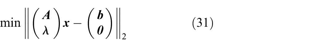
with
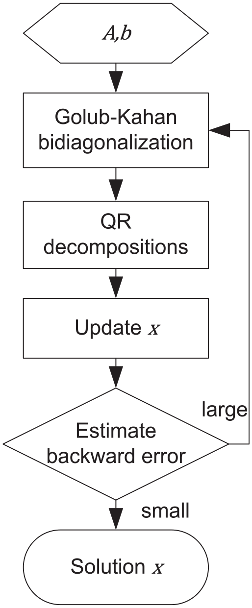
LSMR algorithm flowchart.
For simplicity, considering equation (28) given

Using iterative bidiagonalization


where

with

Define

where
LSMR complexity
The storage requirement and computational complexity can be compared for LSMR and LSQR on
Storage and computational requirements for various LS methods.

LS: least-squares.
STBC scheme based on OCDM
EO-STBC is an MISO space–time coder system based on four antennas on the transmitter side and one antenna on the receiver side. It is a diversity scheme that can accomplish both full diversity gain and full rate via an additional feedback link from the receiver to the transmitter, to update the phase rotations applied in the transmitter; accordingly, both full diversity and array gain are ensured.15,33
The CSI from the receiver is fed back to the transmitter to optimize these rotations with the assumption that they are on time and errorless for easiness. EO-STBC can be simply derived in MCM schemes such as OFDM or OCDM 15 in broadband scenarios.
Multicarrier EO-STBC configuration block diagram is shown in Figure 6 where the data vector


EO-STBC in a multicarrier configuration.
where


which apply rotation to subcarriers. Using the corresponding multicarrier channel model
where
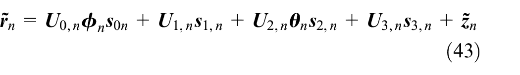
Collecting data over two consecutive OCDM symbol periods, the received vector signal can be written as

where

It is worth noticing that, if the MISO channel is static and the DFrFT-OCDM configuration is used with chirp rate
Proposed space–time decoding
In a frequency- and time-selective fading channel scenario, Doppler shift destroys the orthogonality between subcarriers and the OFDM system is unable to diagonalize the system matrix in equation (45). Consequently, the coupling between at least the adjacent subcarriers is proposed, leading to degradation in the system performance.
Symbols can be detected by ignoring ICI under the near-stationary channel scenario with low Doppler shift character, using only the elements on the main diagonal of the channel transfer matrix. Thus, the OFDM system can be employed due to its low complexity. This indicates that any off-diagonal contents in the corresponding channel matrices
Low Doppler shift EO-STBC receivers can combat cross-talk on each subcarrier separately to enhance the feedback diversity gain. In STBC systems, the channels are generally expected to remain in block static form. In this case, frequency-domain channel submatrices are orthogonal which imply that the symbols can be decoded simply by the simple maximum-likelihood (SML) algorithm; the complexity of the SML algorithm is directly proportional to the number of subcarriers. However, in time-selective fading channels, frequency-domain channel submatrices become no longer orthogonal, so decoding to decrease the effect of cross-talk can be performed by the JML algorithm, which has more complexity than some algorithms such as ZF and DF.1,2
On the other hand, for higher Doppler shift in order to soften the effect of high Doppler shift on the EO-STBC decoding performance, equalization is needed and the angle feedback to the transmitter is not required. In the next section, a novel EO-STBC scheme will be presented.
Open-loop EO-STBC decoding with equalization
The EO-STBC system combined with the OCDM performance under higher Doppler shift conditions can be improved using equalization which raises the receiver’s complication; however, it eliminates the need for the angle feedback to the transmitter. Consequently, the beam steering matrices are simply set to be identity matrices
OCDM EO-STBC system low-complexity equalizers
Low-complexity equalizers can be used with the OCDM EO-STBC system such as banded linear block MMSE, LDLH, and LSMR equalizers which were described in previous studies.3,16,23,34,35
Assuming the perfect channel knowledge, a block MMSE equalizer is defined based on the system matrix
where

where

Similar to equation (21), we can define the MMSE equalizer as

where

Similar to equation (49), the matrix inversion in equation (50) is in the order of
Low-complexity equalizers’ realization
The matrix inversion for equalization (equation (49)) needs a considerable number of
The LSMR realization of either ZF or MMSE solution needs
A novel MIMO-OCDM system
In the last two sections, STBC MISO systems were investigated in detail under the doubly dispersive fading channel, and the combined system with the novel OCDM MCM was introduced. In this section, combining the MIMO system with the OCDM system is investigated under the doubly dispersive channel scenario conditions.
MIMO-OCDM system model
Consider a MIMO-OCDM system with

where

where

The MIMO-OCDM system.
The transmitted data vector

where

where

and
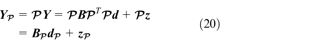
There is a need for a permutation matrix to deal with the MIMO system

and 0’s elsewhere. Using the permutation matrix


where
Both equations (54) and (57) prove that the received data from two different transmitters at the same subcarrier are adjacent and close enough, to assume that they both hold the same transmitted data property. As a result, it is acceptable to claim that the tops and the bottoms of the bandwidths for both of them are close to each other at the top and at the bottom of
MIMO-OCDM system equalization
The linear ZF and MMSE estimates5,36 can be derived by minimizing

where

ZF equalizer performance is reduced because of the noise enhancement. On the other hand, the MMSE equalizer gives the best performance among all types of linear equalizers; 37 however, it is very complicated due to MIMO channel matrix inversion.
The permuted MIMO channel matrix
MIMO-OCDM system with low-complexity equalization
The MIMO-OCDM channel matrix

where

The estimated data vector will be given by

The
Selection of optimal order
We will now investigate the effect of the fractional order
Simulation and results
The uncoded BER performances of the systems are investigated by means of simulation. The channels used in simulation are Rayleigh fading independent channels with exponential power delay profile and Jakes’ Doppler spectrum. The root-mean-square (RMS) delay spread of the channel, normalized to the sampling period
Alamouti MISO OCDM system performance
The decoding algorithms proposed previously are now inspected and compared by means of simulation. The Alamouti space–time coded system based on OFDM, DFrFT-OCDM, and DFrCT-OFDM with the same specifications as in the SISO scheme was considered.
To evaluate the performance of the suggested system, an OFDM transmission is used with quadrature phase shift keying (QPSK) modulation,

Uncoded BER comparison for the classical Alamouti space–time coded OFDM system with time-invariant and time-variant channels.
Figure 9 shows the comparison of the BER performance of the different Alamouti space–time coded systems based on OFDM, DFrFT, and DFrCT using MMSE equalizer in decoding with the classical Alamouti decoding system, based on OFDM under time-variant channel. Using equalization for the Alamouti system decoding improves the system performance compared to the OFDM case under high-mobility conditions (doubly selective channel); in fact, the proposed system using DFrCT-OCDM provides better performance even from the DFrFT-OCDM system.

Uncoded BER comparison for the classical Alamouti space–time coded OFDM system with different Alamouti STBC systems based on OFDM, DFrFT, and DFrCT-OCDM using MMSE equalizer under time-variant channel.
Comparison between the proposed DFrFT-OCDM, DFrCT-OCDM, and OFDM systems using low-complexity equalizers for Alamouti coding is shown in Figure 10.

Uncoded BER comparison for different Alamouti space–time coded systems based on OFDM, DFrFT, and DFrCT-OCDM using low-complexity MMSE equalizer.
It is clear that using a low-complexity equalizer degrades the system performance, because the banded equalizers have an error level because of the band rough calculation error of the channel, which can be improved dramatically by increasing the
EO-STBC OCDM MISO transceiver performance
The proposed multicarrier EO-STBC DFrCT-OCDM MISO transceiver is investigated using simulation under doubly dispersive fading conditions, and then a performance comparison between the novel system and the EO-STBC OFDM MISO transceiver is made.
In Figure 11, a performance comparison between the OCDM and OFDM EO-STBC systems using a block equalizer is shown, and Figure 12 illustrates the results of using a less complex method that applies an equalizer limited to working on

Multicarrier EO-STBC system based on OCDM and classical OFDM with block equalization BER comparison.

Multicarrier EO-STBC system based on OCDM and classical OFDM with banded equalization
As shown in Figures 11 and 12, the BER performance for the OFDM and DFrFT-OCDM systems is almost the same up to approximately 10 dB EB/N0 due to additive white Gaussian noise (AWGN). At higher EB/N0, the BER performance degrades in the banded equalizer case because of the error in neglecting off-diagonals larger than
MIMO-OCDM system performance
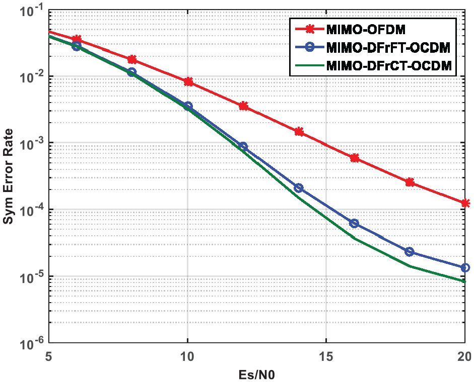
The proposed MIMO-OCDM transceiver will be investigated using simulation under doubly dispersive fading conditions, and a performance comparison between the novel system and the MIMO-OFDM transceiver is made. The simulation is carried out over 100,000 different symbols and different channels. A comparison between the MIMO-OCDM and the MIMO-OFDM systems is carried by using two transmitting antennas and three receiving antennas, with the block MMSE equalizer as shown in Figure 13. From the figure, it is clear that the MIMO-OCDM systems are much improved than the MIMO-OFDM system and the MIMO-DFrCT system is improved than the MIMO-DFrFT system. It can be observed from Figure 13 that the OCDM MIMO systems outperform the OFDM system in the 1% uncoded BER area by 3 dB and in the 0.1% uncoded BER area by 2.5 dB. It is clear that the DFrCT-OCDM system outperforms the DFrCT-OCDM system in the 0.1% uncoded BER area by 0.5 dB.

The MIMO system performance with two transmitting antennas and three receiving antennas using MMSE equalizer.
Comparison between the MIMO-DFrCT and the SISO-DFrCT system is made using the block MMSE equalizer as shown in Figure 14. It is obvious that the MIMO-DFrCT system is better than the SISO-DFrCT system because of the diversity gained for the MIMO system.

BER comparison between the MIMO and SISO DFrCT-OCDM systems with two transmitting antennas and three receiving antennas using MMSE equalizer.
Comparison between the MIMO-OCDM and MIMO-OFDM systems is made using two transmitting antennas and three receiving antennas with the low-complexity banded MMSE equalizer, as shown in Figure 15. From the figure, it is clear that the MIMO-OCDM systems are much better than the MIMO-OFDM systems and the MIMO-DFrCT system is better than the MIMO-DFrFT system. It is also clear that the performance of the banded low-complexity MMSE equalizer is less than that of the MMSE equalizer due to banded approximation.
The MIMO system performance with two transmitting antennas and three receiving antennas using banded low-complexity MMSE equalizer.
Conclusion
In this article, three novel systems have been introduced which are Alamouti STBC MISO MIMO-MCM system, EO-STBC MISO MCM system, and MIMO system, based on the OCDM MCM systems. MISO systems based on Alamouti decoding were investigated and a combination with OCDM was proposed; as a result, the proposed combined system, that is, MISO OCDM, improved the system performance. To provide a better understanding of the proposed system, EO-STBC transmission was studied over a frequency- and time-dispersive channel and then compared with the other systems. In addition, a multicarrier scheme was deployed to soften the time-based dispersion resulted from frequency spreading due to Doppler shift, which could lead to a major performance degradation because of losing the subcarrier decoupling. Usually, in the case of low Doppler shift and near-static channel situations, ICI can be ignored, while in the case of higher Doppler shift a general multicarrier system based on the OCDM with equalization can be used. The results show that OCDM can hold more channel energy along the main diagonal, compared to classical OFDM, which leads to improved system performance and decreased equalization complexity. Finally, the MIMO-OCDM systems were proposed to improve the performance of the MIMO-MCM systems under doubly dispersive channels. The novel MIMO and MISO-OCDM systems were investigated using low-complexity equalizers and shown to provide better performance than the MIMO and MISO OFDM systems.
Future work is directed to combine the network coding technique on the system to exploit the significant advantages of this technique, in terms of channel capacity and BER, and to reduce the automatic repeat request (ARQ) as proved in Attar and colleagues.38–41
Footnotes
Handling Editor: Ashish Kr Luhach
Author contributions
A.A.A.S., H.H.A., and M.R.K. prepared the comparative analysis report. H.H.A. and B.K. used the selected tools for performing simulations. A.A.A.S. and H.H.A. wrote the manuscript and M.R.K. and B.K. suggested various changes.
Declaration of conflicting interests
The author(s) declared no potential conflicts of interest with respect to the research, authorship, and/or publication of this article.
Funding
The author(s) received no financial support for the research, authorship, and/or publication of this article.