
Abstract
As semiconductor technology scales into the nano regime, hardware faults have been threats against computational devices. Cloud systems are incorporating more and more computing density and energy into themselves; thus, fundamental research on topics such as dependability validation is needed, in order to verify the robustness of clouds for sensor networks. However, dependability evaluation studies have often been carried out beyond isolated physical systems, such as processors, sensors, and single boards with or without operating system hosts. These studies have been performed using inaccurate simulations instead of validating complete cloud software stacks (firmware, hypervisor, operating system hosts and workloads) as a whole. In this article, we describe the implementation of a fault injection tool, which validates the dependability of a commercial cloud software stack. Hardware faults induced by high energy density environments can be injected; the fault propagation through the cloud software stack is traced, and quantitatively evaluated. Experimental results show that the integrated fault detection mechanism of the cloud system, such as fatal trap detectors, has left a detection margin of 20% silent data corruption to narrow down. We additionally propose two detection mechanisms, which proved good performance in fault detection of cloud systems.
Keywords
Introduction
The increasing use of wireless sensors that generate massive data combined with the need to process these data efficiently has given an enormous importance to the cloud computing paradigm. 1 While the basic components of IoT (Internet of Things) systems have limited storage and processing capabilities, they have usually seamless access to the Internet which allows them to profit from the abundant (and usually low-cost) resources available in the cloud. 2
Reliability of the cloud is a major concern, considering its intensive use and remote communication nature. A cloud system should provide the services it is designed for with robustness; 3 this fact induces additional challenges to its design and development. Verification, validation, and testing techniques should be used to ensure reliability of these systems.
There are many kinds of reliability threats that cloud platforms need to face. 4 According to the source of threats, we classify them into two categories: external threats and intrinsic threats. External threats include electric failures, system overload, system misconfiguration, security threats and attacks, and natural disasters (e.g. Hurricane Sandy 5 ). Intrinsic threats include software problems (e.g. immaturity of the software stack) and hardware failures. Unlike the external threats, the errors or faults (which may finally lead to a failure, as depicted in the “Background” section) originated from the internal threats generally have an incubation period, before failures manifest themselves. This may bring more uncertainty to the system’s fault detection, and consequently, has been a permanent and serious concern to platform maintainers.
In addition, hardware failures manifest more frequently in the electronic devices as semiconductor technology scaling into the ultra-deep submicron regime. 6 The combinational logics in processors make them more vulnerable, compared to the sequential logic. An experiment toward a DLX superscalar architecture shows that nearly 90% of errors came from combinational logic units.7,8 An error report by Rashid et al. 9 from 950,000 personal computers shows that approximately 39% of the reported hardware errors about microprocessors are intermittent. Therefore, we adopt the intermittent fault as our evaluation model with combinational logic units (and register file) as fault injection targets.
Moreover, we believe that the dependability of the software stack of a cloud system remains unclear. The reason is that failures induced by intrinsic threats are hard to trace, especially during the simulation step at the granularity of instructions. This granularity may provide comprehensive information to explore the fault propagation in both hardware and software, in comparison with message-level fault injectors (e.g. ORCHESTRA 10 ), only collecting messages such as local time and number of received messages. Accordingly, implementation of an instruction-level fault injector for cloud systems might help researchers to model the propagation and identify the root cause of the intrinsic failures in a cloud, and this is helpful for fault detection and diagnosis methods design.
In order to validate the dependability of a cloud against hardware faults, we propose to perform fault injection simulations and use the cloud computing system as a target. From a design perspective, it would have been a very complex task to develop a cloud simulator from scratch, with the requirement of a full-system simulator, that is to meet the need of supporting interrupt handlers, boot loader, memory management, and other functions to run operating systems (OSs). In addition, we also needed to simulate the cloud firmware and the hypervisor in order to run multiple OS hosts upon; this posed an extra weight in terms of complexity on the system design. As a benefit, only dynamic instructions, that is, instructions that have been currently executing in the CPU pipelines, unlike static fault injection technologies,11,12 are injected and traced and ultimately logged during the simulation. This ensures the exclusion of static instructions from the faulty trace and guarantees the analytic accuracy of fault modeling by minimizing the redundancy of each trace. We set up a Fault Behavior Tracing (FBT) system integrated with a full-system simulator, based on which a commercial cloud system runs inside. Using FBT, we simulate the hardware faults originated from inside of the processor and monitor the fault behavior of the cloud software stack.
In this article, the vulnerability of a cloud system against hardware faults is evaluated, and the propagation of faulty instructions through the software stack is quantitatively studied. The failure circumstances of the cloud system are traced and modeled. Based on this study, we have also implemented two fault detection mechanisms to narrow the dependability margin that state-of-art cloud systems have left over.
This article is organized as follows. The “Background” section presents a short background on validation techniques to check reliability of clouds. The “Design and implementations” section presents the design and implementation of our simulation tool, named FBT; the fault injection methodology is also described in this section. The “Experimental results” section presents the validation experiment. Based on the result analysis, fault detection mechanisms are proposed and implemented in FBT, and the detection performance is also evaluated. The “Related work” section discusses related work, and the “Conclusion” section concludes the article.
Background
In this section, we introduce the terminology on system dependability used throughout this work. The fault models used in the reliability validation experiment in the “Experimental results” section are also presented, through a selective survey of the presence and impact of semiconductor devices lifetime in computing systems.
Terminology
The basic definitions of dependability of computing systems can be traced to 1982 in Lee and Morgan 13 and have been discussed by Avizienis et al. 14 and Salfner et al. 15 In this article, we will use the concepts summarized by Kondo et al. 16 where they describe the basic threats to reliability, namely failures, errors, and faults:
Failure: An observable event that occurs when the system deviates from its correct state and therefore it fails to operate as planned.
Error: The part of the total state of the system that may cause a failure. When an error does not cause an external failure, it is a dormant error. Those which provoke a failure are active errors.
Fault: The hypothesized cause of an error.
Hardware faults may have multiple effects on the state of programs at runtime, for example, the silent data corruption (SDC), mask, and benign fault: 17
SDC: Silent data corruption, a fault that has not been detected by hardware, OS, or other mechanisms in the system, and ultimately leads to program errors.
Mask: A fault that has been aborted during the propagation process across layers of the cloud system.
Benign fault: A benign fault is a fault that has not been masked but allows a program to continue execution after the occurrence of the fault.
Hardware fault models
Premature advances in technology have impelled a resurgence of interest in intermittent faults. 18 The driving forces include shrinking geometries, smaller interconnected dimensions, lower power voltages, and decreased noise margins, all of which have a negative impact on chips’ lifetime and yield. The underlying physical mechanisms make intermittent faults characterized as follows:
Burst. Unlike transient faults due to single-event upset (SEU), intermittent faults come from wear-out, as age and wear take their toll on the electronic device. As going deeper in age until the wear-out phase, the fault begins to occur in bursts, each of which ranges from orders of cycles timescale to milliseconds or even seconds.
Irregularity. Intermittent faults are expected to occur under some particular situations, such as temperature increase, voltage drops, noise perturbations, and so on. This indicates that intermittent faults can hardly be modeled in some distribution, which is named irregularity.
Repair. An intermittent fault usually manifests in the same subunit of the device. Replacement of the fault component would eliminate the intermittent fault.
Design and implementations
In this article, we aim to evaluate the vulnerability of a cloud computing system quantitatively. Our scheme is to set up a full-system simulator, based on which we inject hardware faults into dynamic instructions in CPUs, and model the propagation behavior by tracing the instruction sequence until the faults are detected or the workloads are accomplished. In this section, we introduce the implementation of our FBT system. We use the FBT simulator based on the well-known software asset management (SAM) 19 to simulate the considered case studies. The fault injection methodology configured in the experiment is also described.
Derivation of fault injector’s implementation level
Since there are multiple levels for fault injectors, and designs at different levels may have different effects on performance and accuracy, we need to make some trade-offs between levels, before a simulator is implemented. Some fault injection tools based on ASICs (application-specific integrated circuit) or FPGAs (field-programmable gate array) can simulate faults with excellent fidelity. However, ASIC-implemented fault injection tools have limited fault injection precision (i.e. irradiation of the ASIC chip with a laser source in Samson et al. 20 ). The register-transfer-level (RTL) validation tools also have limited simulation performance that are not suitable for large commercial software workloads. Preliminary work shows that the booting sequence of the Solaris OS may take tens of years to complete, when using an FPGA-implemented tool. 21
Similarly, software-implemented simulation tools focus on the verification of CPU prototypes and performance evaluation, such as SimpleScalar, 22 which has implemented simulation of super scalar prototypes at the instruction level. Other tools such as Simics, 23 GEMS, 24 and GEM5 25 focus on architectural performance verification; NS3 26 meanwhile is a network simulation platform. Some of the simulators mentioned above are full-system simulators, but none of them supports virtualization technologies such as the virtual machines (VMs) and cloud infrastructure. Our FBT is based on SAM, which is a full-system simulator, designed to assess the feasibility of virtualization environment. Aiming at evaluating the reliability of cloud systems, we implemented (1) fault injection modules used to inject faults into target locations and to sustain fault during a certain time; (2) fault models, needed as a dictionary indicating the fault types (e.g. bit-flip, stuck at), sustain duration, and burst length (for intermittent faults); (3) controller, to start/terminate/restart the fault injection campaigns, and recognize infinite loop and blue screen; and (4) trace monitor, responsible for recording each instruction into the trace file and necessary information such as privilege mode, exceptions, core number, and so on, and other components needed by a fault propagation tracer. FBT supports the running of firmware, hypervisor, VMs, GuestOS, and user applications on top of it, as well as configurations for a cloud system that are supported in SAM.
Architecture of FBT
FBT is set up to simulate fault propagation from individual units of processor throughout the software stack in the cloud computing system. Currently, the simulator supports fault injections into the address generator, decoder, arithmetic logic unit (ALU), floating-point unit (FPU), and register files in the processor, and monitoring trace from the instruction buffer and state registers (seen in the left side). Three types of hardware faults can be injected, and software is simulated with the granularity of single instructions. The software stack is monitored by FBT modules we developed (in red brown color in Figure 1): monitor interface, trace monitor, trace analyzer, controller, and fault behavior collector.

The architecture of FBT (Fault Behavior Tracing system).
The overall architecture of FBT is described in Figure 1. FBT consists of two main components: the software operating environment, and the reliability verification component. The former simulates the whole software stack of the cloud computing environment, on the full-system simulator SAM, with a single-instruction granularity. The reliability verification modules treat SAM as a fault injection target. First, through the analysis of each module of SAM, we have performed code-level modification of the processor simulator, including the addition of the fault injection interface and the monitor interface, which implements fault injection for multiple units in the processor. The fault injection interface has the purpose of destructively striking the instructions that stay in each unit. For example, for the multi-bit flip fault of the decoder, the instruction field and the operand field are re-decoded, according to the flip position by the fault injection module, and then the result of the re-decoded instruction is sent to the next instruction in the instruction sequence. At the same time, the trace monitor records the instructions (before and after modification). In this way, the fault injection and trace tracking functions of a simulation step with granularity of a single instruction are setup.
Furthermore, we designed and implemented the trace analyzer module to obtain comparison of traces. For example, when the fault occurs within the same fault location but in different time (instructions or data), the trace analysis module shows the differences in fault propagation. In the processor of FBT, functional units such as ALU, FPU, decoder, AGEN, and register file have been selected as fault injection targets. The specific fault injection locations in each individual injection target are described in Table 1. For the decoder unit, we perform the fault injection by perturbing the opcode or operand field of the target instructions; the fault injection location should be the decode buffers. Different from decoder, the faults cannot be injected by simply the operand field of the (floating-point) arithmetic logic instructions for the ALU and FPU unit, because SAM simulates the prototype of the UltraSPARC T2 processor, which is a RISC instruction set (SPARC V9) processor. The operand field of (floating-point) arithmetic logic instructions is defined to be a register number. In FBT, the fault injection of ALU and FPU is implemented by parsing the register number from the target instruction, and then modifying the data of the specific register. Through source code analysis, we found that the NPC register (Next Program Counter register) is used to indicate the address of the next instruction to be fired in the SAM simulator. Hence, for the AGEN unit, we modified the instruction address in the NPC register right after the current instruction is written back. The injection of the register file is also a modification operation to the target register, which is similar to ALU and FPU, but the modification does not need to be synchronized with any instructions being executed. Therefore, there is a relatively high probability of the masked faults during fault propagation (see the “Experimental Results” section for details).
Target units and corresponding fault locations.
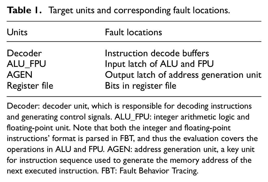
Decoder: decoder unit, which is responsible for decoding instructions and generating control signals. ALU_FPU: integer arithmetic logic and floating-point unit. Note that both the integer and floating-point instructions’ format is parsed in FBT, and thus the evaluation covers the operations in ALU and FPU. AGEN: address generation unit, a key unit for instruction sequence used to generate the memory address of the next executed instruction. FBT: Fault Behavior Tracing.
Due to the millions of experiment instances that are necessary in order to ensure the confidence interval of the experimental results, we need to inject faults automatically. We implemented the blue screen recognition and the dead loop detection in the controller module, to recognize the system crashes which are caused by illegal memory address access, trap stack overflow, and other serious failures.
Fault injection methodology
Fault models for transient faults, intermittent faults, and permanent faults are listed in Table 2. The fault location (i.e. position of the faulty bit) in each target is selected randomly and follows a uniform distribution. Note that the simulation of intermittent faults, as depicted in Figure 2, consists of three parameters: fault activation interval (TA), fault inactivation time interval (TI), and burst length (Lburst). 27 At RTL level, it has been validated that the separation between fault activations (TI) does not influence failures rates under the assumption of fixed activations (TA).
Fault models in this work.


Intermittent faults configuration including faults parameters: TA, TI, and Lburst. 27
The timescale of each burst is specified as orders of instructions, due to the implementation level of our fault injection tool. Moreover, in accordance with the characteristic of the intermittent fault mentioned in the “Background” section, intermittent fault injection in FBT is designed as follows: (1) Burst. Each burst of fault generates a faulty instruction and the fault parameter burst length (Lburst) can be specified as two, four, eight, and sixteen instructions respectively in FBT; (2) Irregularity. The burst number for intermittent fault in each emulation instance is randomly selected; (3) Repair. The fault location remains unchanged throughout one emulation instance in the experiment.
We gathered statistics for a 2-month period fault injection tests of the Mibench workloads, 28 including BasicMath, Dijkstra, FFT, Qsort, and StringSearch. For each instance, one of the three types of fault is chosen and injected into the target fault location. For intermittent faults, an overall of 24,000 runs (300 injections × 4 units × 5 benchmarks × 4 Lburst) is conducted; for transient faults and permanent faults, we conducted 12,000 and 6,000 instances respectively, since there are two types of faults with permanent stuck@0 and permanent stuck@1 faults, compared to transient faults with only one. The simulator is in 1c1t (1 core 1 thread) configuration, as the multi-core configuration is left for future work.
Experimental results
In this section, we evaluate the dependability of the software stack against hardware faults for cloud computing systems. We use the FBT simulator based on SAM to simulate the considered case studies.
Dependability evaluation of the software stack for a cloud computing environment
Hardware faults may have no effect on the state of the program at runtime, and ultimately yield correct result (called a masked fault); or they may lead to a state corruption. In the latter case, if the state corruption is not detected by a fault detection mechanism, and if it fails to be masked during the propagation process either, it may result in an SDC. Hardware faults can be masked by the following reasons: logical masking, latch window masking, and electrical masking. However, the effectiveness of these masking mechanisms tends to decline due to the shrinking feature size of the semiconductor device. 29 From the fault injection campaign, we found that the integrated hardware fault detection (except for user-customized redundancy mechanisms) is still dominated by fatal traps in a commercial cloud system.
As shown in Figure 3, for all fault injection instances, the fatal trap accounted for 42.87%, the masked faults accounted for 38.06%, and the SDC accounted for 19.06%. In the case of removing the IRF file, the proportion of fatal traps further increased, which accounted for 56.93% (fatal trap), 20.50% (masked), and 22.56% (SDC). The IRF file is sequential logic, and the symptom distribution is obviously different from the other three units. The masked faults reach up to 90.75%, and the SDC is 8.55%, while the fatal trap is less than 1%. The reasons for this difference are as follows: (1) The faulty data in the register have been rewritten before it is referenced, and (2) the faulty data are referenced by a dynamic dead instruction, which shows the positive impact of the uncertainty of data correlation on the fault shielding ability.

Dependability evaluation of cloud software environment.
Furthermore, we distinguished the privilege level of the instruction triggered by the fatal trap and divide it into application fatal trap (in non-privileged mode) and OS fatal trap (in privileged mode). The ratio of application fatal traps is 88.13% (50.21%/56.93%), compared to OS fatal traps, which accounts for less than 12%.
Note that application fatal traps may trigger OS fatal traps during execution, and these traps are not counted in. Therefore, this ratio does not represent frequencies of all the fatal traps but may represent the probability that a fault propagates into this privileged mode and is detected in the same privileged mode. For example, the AGEN unit is dominated by 0x9 and 0x10 traps in case of a fault. The 0x10 trap (illegal_instruction trap) mostly occurs when the Program Counter (PC) register is changed by the fault, causing miss in Cache (0x9) or memory. When the processor enters HP mode (hyper-privileged mode) to execute the service routine of 0x9 trap, the fault continues to disrupt the value of the PC register, causes the instruction address to fall into the non-code area in memory, and further triggers the 0x10 trap. In such case, we record this fault detected by 0x9 trap in non-privileged mode.
The 20.50% proportion of the masked faults indicates fault shielding capabilities throughout the cloud system in FBT. Once a fault has been injected into an instruction, it will cause an architectural state corruption directly, unlike the lower level fault injection tools, which may loss the corruption probability during the fault propagation from circuit level to architecture level. It is important to remind that we did not implement FBT in lower level also to ensure the cloud software stack to be simulated in affordable time.
The possible reasons of the masked faults are the following: (1) the fault is injected in the target field of the branch instruction, but the branch jump does not occur; (2) the sign bit of an arithmetic operation determines the branch instruction to jump, but the error result does not affect the sign bit; (3) the fault changes the opcode, but the final result remains unchanged, such as “add %o3, 1, %o3” becomes “or %o3, 1, %o3.” If the value of the o3 register is even, the result of the instruction operation is not affected; and (4) the NOP instruction is injected into the Sethi instruction. Since the destination register of this instruction is g0, the value of the register is not affected, and so on.
SDC indicates the fault which will lead to erroneous results. For the three combinational units, the average SDC has reached 22.56%, while the register file is lower but has still reached 8.5%, which shows the margins the software stack has left over for other detectors to narrow. We have implemented two other detectors in FBT, which have been incorporated into FBT and performed well in reducing the proportion of SDC (see the “Proposed detection mechanisms” section).
Dependability analysis of fault time variations
Figure 4 shows the variation of symptoms along with the duration of the faults (X-axis). For transient faults, the masked faults have the highest proportion, but as the fault duration increases, the share of mask symptoms becomes lower, and it is minimized at the permanent stuck@1, indicating that the fault detection mechanism achieves good performance in case of physically irreversible hardware faults. Note that the SDC rate is slightly lower at permanent stuck@0 compared to the permanent stuck@1; since the default value of most architecture-level states is 0, this fault type may cause architectural state corruption with lower probability.

Comparison of symptoms in variation of fault types and durations.
Proposed detection mechanisms
To reduce the SDC, which reaches up to 20% in the cloud environment, we designed two fault detectors and integrated them into the FBT system. The evaluation proved good detection performance of the proposed mechanisms.
High detector
In addition to system calls and only a few interrupt handlers that introduce many continuous OS instructions, only tens or hundreds of instructions are executed continuously in most OS modes. However, in case of a fault, such as a fault in the PC register (or a memory load instruction), an incorrect instruction (or data) address is produced. Since the wrong address is accessed, the processor must enter in the HP mode to handle the cache miss (0x9 trap), introducing a large number of OS instructions.
Since there are no such detectors, we integrated the high detectors in FBT. The detector uses a performance counter which is common in the microprocessor to accumulate the number of continuous instructions executed in the P mode (or in the HP mode). When the preset threshold is exceeded, the detector will produce an alarm. Accordingly, when the high symptom is detected in P mode, there is a high OS fault detected; and if detected in HP mode, we call it a high hyper fault. The high detector shows a limited performance overhead. 30
The detection results are shown in Figure 5. After adding the high detector, the SDC rate decreased from 20.49% to 4.45%, and shows that the detection effect of the high detector was obviously positive. Among them, the high OS rate contributed with 15.6% and the high hyper rate contributed with 0.43%; however, we believe that when SAM is extended to more VMs, the high hyper detector will show better detection performance as more interactions in hypervisor will be raised.

Detection contributions of detectors integrated in FBT.
Hang detector
In addition to high detector, we also implemented another detector called hang detector. The hang detector records the number of branch instructions executed in the privileged mode and determines whether it exceeds the profile threshold (normal maximum×10) to detect an infinite loop, taking a small performance overhead (e.g. 1.6% in distributed OS 31 ). The effect of hang is not obvious, and only few instances have been detected in the experiment. However, taking account the harmful results induced by the hang symptom, like dead loop or SDC after long-term delay, the hang detector is needed.
Latency of the detectors
Detection latency is a crucial factor for detection mechanisms. Long time delays may have negative impact for the reliability strategy to recovery or even make the state irreversible. In this work, the latency is described as the number of instructions from architectural state corruption to fault detection. The injected faults that have been masked in their propagation to the registers are discarded because we believe it is unnecessary to consider the simulation from combinational logic to registers at the architecture level, which may be mainly considered in lower levels, such as FPGA or ASIC design. As shown in Figure 6, faults that have been detected by fatal trap detectors are detected in less than 40 instructions in average. Over 58.9% of intermittent faults are detected within 10 instructions and 97.8% within 20 instructions. About 73.7% of symptoms are detected within 1K instructions, and 97.7% within 100K instructions. This can be handled with hardware checkpointing schemes, 32 while the higher latency cases can be handled with software checkpointing schemes. The state transition diagram of the fault injection methodology and fault detection mechanisms in the FBT system is shown in Figure 7.

Detection latency of symptoms in variation of fault types.

State transition graph of FBT after integrating high and hang symptom detectors.
Moreover, an interesting phenomenon has been found: SDCs caused by the transient fault have the highest proportion, exceeding the probability of 1/3 (34.6%). It shows that for the cloud system, the evaluation proved good detecting performance of the proposed mechanisms. Even if there are more software levels to improve the probability of the masked faults and fatal traps detection compared to environment only with OS hosts, the system still needs to be enhanced in order to deal with transient fault sources such as crosstalk.
Related work
Large-scale field studies on failure characteristics of individual components,33,34 such as DRAMs and hard disks, have been investigated in real-life cloud systems. The high-level characteristics of hardware failures along with trends and patterns are observed based on statistics of repair events. Google 34 found that DRAM error behavior differs from commonly held assumptions; that is, memory errors are dominated by hardware errors, rather than software errors, and environment (i.e. temperature) only has a very small effect on error rates.
Wang et al. 35 propose a fault detection method to make use of symptoms in the RTL level, such as core status (DeadLock) and core-memory events (Invalid Packet) in order to detect intermittent faults. Rashid et al. 36 make a preliminary study of intermittent fault propagation at the program level. Arasteh 37 also focuses on the programming level and investigates the inherent effects of different programming structures on the program resiliency. Mueller-Gritschneder et al. 38 set up a processor simulator supporting cross-layer evaluation, but unlike FBT, it is used for soft-error resilience and embedded systems.
Fault injection experiments39–41 have been conducted to measure the reliability of OSs. Some of them are able to emulate upsets in FPGA fabric and microprocessor cache lines and special registers. 42 In Le and Tamir 43 and Pham et al., 44 fault injection tools implemented in cloud environments are proposed. The authors use them to evaluate and characterize dependability of OSs, taking advantage of virtualization (Virtual Machine Monitor) for fault injection into non-virtualized systems (GuestOS). As a result, the fault injection modules can only be implemented in the Virtual Machine Monitor, and only misbehaviors of the GuestOS can be studied.
L Feinbube et al. propose a fault injection method 45 and a stress-oriented dependability testing model 46 to ensure cloud reliability assessment, which relies on exchangeable executables when particular fault types are injected, and may result in limited coverage of the space of possible faults.
Yamato et al. 47 proposed a light-weight restoration method on OpenStack, promising effectiveness in restoring all virtual resources within a short time when physical servers or VM processes are down. The method is implemented in software and can be used after a fault is detected. Thus, this method can be complementary to our method. Some other approaches for assessing cloud system reliability and security have been also explored in Yuan et al., 48 Herscheid et al., 49 Zimba et al., 50 and Wang et al. 51
However, as stated in Cheng et al., 52 “resilience to errors in the underlying hardware is a key design objective for a large class of computing systems, from embedded systems all the way to the cloud.” To the best of our knowledge, our work is one of the few that sets up dependability models and the simulator of cloud systems, in order to understand failure behaviors originated in different levels of the CPU or bit-flips in registers. We believe that assessment based on FBT as presented in this article can provide more realistic dependability models, considering the dynamic and cross-layer simulation environments of real-world cloud systems.
Conclusion
This article makes an attempt to investigate the possibility of exploiting a fatal trap as a candidate symptom to protect a cloud system against hardware faults, taking into account the dependability of the software layers in the runtime dynamic execution environment. In order to do this, a fault behavior tracing tool, FBT, has been set up on top of a full-system simulator. Based on FBT, we were able to inject faults at the architecture level (such as bit-flips in registers), and simulate fault propagation through a realistic software stack, including firmware, hypervisor, Solaris OS, and workloads.
The fault behavior has been quantitatively analyzed with respect to fault types, durations, and other factors. Assessment results show that the SDC has reached more than 15% in total in case of a cloud system under hardware faults attack. Then, a high- and hang-based fault detector has been proposed and incorporated into the cloud environment, which has reduced the SDC down to 4.45%. Considering the near zero hardware overhead, the performance improvement of the proposed method is obvious. Going one step further, error propagation patterns of fault models can be extracted from logs, and can be used as diagnosis essay and applied to make failure predictions.
Footnotes
Handling Editor: Mohsin Iftikhar
Declaration of conflicting interests
The author(s) declared no potential conflicts of interest with respect to the research, authorship, and/or publication of this article.
Funding
The author(s) disclosed receipt of the following financial support for the research, authorship, and/or publication of this article: This work is partly supported by the Natural Science Foundation of Beijing (Grant No. 4174091), Research Funds for Education Committee of Beijing (Grant No. KM201711232013), and Key Research Project of Beijing Natural Science Foundation (Grant No. Z16002).