
Abstract
This article investigates the possibility of advancing discrete manufacturing using system architectures that are developed for Collaborative Process Automation Systems. Collaborative Process Automation System is a technology that has the potential to achieve production excellence for process industry. However, not much attention has been paid on using the architectures based on Collaborative Process Automation Systems for discrete manufacturing domains. In this article, we propose a base architecture consisting of three layers, and we discuss various alternatives to make the communications among the layers. We consider legacy components in the proposal, in contrast to most of the related works. In order to show the practicality of the proposed alternatives, we present an example that has been implemented in an ongoing project at ABB Robotics in Sweden.
Introduction
In today’s open globalized market, an intense pressure is on manufacturing industries to stay competitive in the future market where advanced manufacturing technology plays an important role. With the growth of emerging technologies such as industrial networks and cloud computing, a rapid movement has started toward shifting the traditional industries into smart factory setups where the information from manufacturing will help improving it. Industry 4.0 presented by Lasi et al. 1 and in Europe 2020 Strategy 2 envision such a future market.
Low-volume high-mix (LVHM) manufacturing has become a trend for many discrete manufacturing (DM) industries to remain competitive in the market by producing various types of products instead of only one type. However, LVHM manufacturing poses a high level of dynamicity to the production process. The adversity of the product range can negatively affect the production performance since it introduces a big overhead for adaption of the manufacturing process to cope with such an adversity. Such overhead increases with the lack of adequate information from the production process in a traditional factory setup where systems work disjointly and no comprehensive view of the whole process exists. In DM industries, typically corrective actions are taken because of an occurring process problem. Since the problem has already occurred, the result may often reduce the efficiency and increase cycle time. Often, delays in the production cannot be prevented or properly compensated since the data from the production are not accessible or cannot be fully utilized to predict the delays and/or take proper actions to compensate them. For such proper/preventive actions to be taken place continuous monitoring and scheduling are required.
With smart manufacturing solutions, manufacturing excellence can be achieved through making all information from the manufacturing available. The data then can be used for detecting and predicting problems and providing decision making for improving manufacturing performance according to Saez et al. 3 In order to enhance a traditional legacy factory setup toward a smart factory setup, all data from the manufacturing should become available from the shop floor devices and systems. This requires that all such devices and systems are fully connected and their data are collected for monitoring and analysis. Many works in the literature have addressed possible solutions to connect and collect data, where most of them have used the cloud models. For example, the proposal by Ahn et al. 4 presented two levels of computing, being cloud and fog computing, to accumulate data for smart factories. Similarly, the work by Trinks and Felden 5 presented an idea of using edge computing architecture to support data collection in smart factories.
In addition, process industry has been using Collaborative Process Automation System (CPAS) (https://www.arcweb.com/industry-concepts/collaborative-process-automation-system-cpas-concept) technology over the years as a method to achieve operational excellence. CPAS vision was introduced by ARC, which is a research and advisory firm in Boston. 6 CPAS provides continuous monitoring that aids at improving the production. CPAS can also decrease the complexity of dealing with a multiple system environment, which is typical in DM where diverse types of systems may have been used to manage different parts of the production process. Furthermore, CPAS can provide relevant data for different end users. Examples of these relevant data include the following: (1) productivity and performance metrics such as key performance indicators (KPIs) to the management level; (2) detailed steps for users, showing how the production of a specific product was done and if there is a need of improvement to the engineering level; and (3) choice of recipes, current process, system alarms, and maintenance issues to the operator level. The unified environment that CPAS offers provides a comprehensive view of the whole production through enabling collaboration of different roles in a process or manufacturing plant where the specific requirements of the production can be identified. CPAS can enhance toward developing a smart factory setup by shifting a traditional automation setup to a fully connected and flexible setup where data from the process are always available for analyzing and decision making. An example of a CPAS is the ABB 800xA system, which is a network of interconnected sensors, actuators, controllers, and computers that continuously control and monitor processes, which was proposed by Hollender et al. 7 As discussed earlier, use of CPAS technology for DM can:
provide continuous monitoring and control processes that aid at improving the production;
decrease system complexity by enabling a uniform environment;
make taking actions based on “preventive information” possible;
enable countermeasures before a production stop occurs;
facilitate developing smart factory agenda.
Contribution
Although the CPAS technology has been a promising approach for process industry, in this article we investigate alternative system architectures based on CPAS to be used in an existing DM setup. We first discuss about the key parameters that affect such an architecture, based on which we propose a base architecture with three layers. Furthermore, we look at possible alternative approaches for communication of each layer with other layers for each of which we discuss the trade-offs. At the end, we present one system architecture example with the most suitable communication approach for each layer based on an ongoing project in the context of Production 2030 vision in Sweden (https://produktion2030.se/en/projekt/process-automation-for-discrete-manufacturing-excellence-padme).
Paper layout
Section “Architecture-affecting parameters” presents the parameters that affect the proposed architecture, while section “Base architecture” presents a base architecture for enabling smart factory in DM. Section “Architecture layers communication” presents alternatives for communication between three layers in the proposed architecture. Then, section “Example architecture” presents an example from an ongoing project at ABB in Sweden to show the practicality of the alternatives. Section “Conclusion and future work” presents the conclusion of the article.
Related works
Smart factory is a vision within the context of Industry 4.0 with focus on using advanced technologies and manufacturing data. Several works addressed various directions in this field, including advancement in physical equipment, network infrastructure, and handling big data applications. The work by Trotta and Garengo 8 presented the key challenges in each of the mentioned directions.
In the context of architecture proposals, several works investigated different architectures to enable smart factory design. For instance, the work by Benkamoun et al. 9 presented a framework to identify different perspectives of smart factories focusing on functionality and entities. Moreover, the work by Wan and coworkers10,11 mentioned four layers in the architecture of smart factory including physical devices, network layer, cloud layer, and terminal layer for operators. From the architecture point of view, most of the works in the literature mention the cloud as the key component in the smart factories. The trend is inheriting from IT services where computation and data are moved away to large data centers, according to Jadeja and Modi. 12 These works include using the cloud computing technology in home automation and mobile services, such as in the studies by Givehchi et al. 13 and Dickey et al. 14 and in the supervisory control and data acquisition (SCADA) systems by Chen et al. 15 In addition to the aforementioned works, some efforts have been put on developing architectures. For example, the work by Kavakli et al. 16 presented a software architecture for smart manufacturing. The main idea of this architecture is to provide a flexible architecture to support decision making, to reduce delays and failures in production. Moverover, the work by Jazdi 17 presented usage of cyber-physical systems (CPSs) for Industry 4.0. It also evaluated the CPSs in various characteristics, such as flexibility and mobility. The work by Cogliati et al. 18 further developed a CPS architecture to consider intelligent mechanisms and introduce the notion of iCPS. In this architecture, intelligent embedded sensors are connected in the manufacturing in order to enhance the decision making in production.
For the communication infrastructure, the OPC Unified Architecture (OPC UA) protocol seems to become a potential communication protocol for future smart factories. Leitao et al. 19 argued that OPC UA can be moved from traditional communication architecture to a service-oriented architecture in a way to enable the infrastructure for manufacturing system communication. In this regard, Girbea et al. 20 proposed an architecture mainly focusing on optimization of industrial applications in which OPC UA is used for communication.
In this work, we focus on a smart manufacturing architecture suitable for DM, and in contrast to the other proposals, we do not fully rely on cloud computing. Moreover, we consider legacy systems in an existing factory when proposing architecture alternatives, which is not part of other works.
Architecture-affecting parameters
In this section, we look at the key parameters that affect a system architecture for enhancing a legacy DM factory into a fully connected smart factory setup. With this regard, we have identified the following two key parameters that affect the design of such an architecture (1) what applications should be made available with the data collected from the shop floor devices and systems, and (2) where each application is executing and how the input and output data to and from each application are provided.
To address the former design-affecting parameter (1) we can classify the output information provided by the system into two categories: (a) the information that requires a near to real-time action/decision making, for example, alarm notifications to operators for which a fast action is required to be taken, and (b) the non-real-time information that is used for long-term decision making such as optimization purposes, for example, guidelines to optimize the production throughput. For practicality reasons, we have simplified these two categories as the following applications: (a) visualization of operational data application (VOAP), for example, operators alarm and event notifications and (b) manufacturing management application (MMAP). To address the latter design-affecting parameter (2), it should be specified where each application executes and how the input and output data to and from it are provided. Since visualization is often one of the main functionalities provided by a CPAS such as ABB 800xA system, VOAP can run within CPAS using the provided services in such systems for visualization of data. The CPAS can provide such visualization of data in the production cells, for example, via provided panels to handle human machine interfaces (HMIs). Since VOAP will run within CPAS, the input data for this application will be provided by CPAS through connection to production cells. In order to connect any such cell to CPAS with the aim to extract the data within different systems and devices in the cell, all such systems and devices that collect, process, or store data in the cell should be connected to CPAS.
Regarding addressing requirement (2) for MMAP, although it is possible to develop such an application in CPAS, typically it is developed in a separate system with more enhanced capabilities for developing such an application. If this application is being developed in a separate system as CPAS, then it is required to specify a method for transferring data to and from this application.
In the case of developing this application in a separate system than CPAS, it is required to specify how the data are provided to and from this application. With regard to the input data to MMAP, since the data are collected into CPAS, it is more suitable to provide the required data for MMAP through CPAS instead of providing another connection to systems and devices for pulling data which may result in overloading those systems and devices. Hence, it is required to specify how MMAP and CPAS communicate the data. Please note that the abbreviation are listed in Appendix I of this article.
Base architecture
In this section, we present a base architecture with three layers based on the identified parameters presented in the previous section, for enhancing a traditional DM factory setup with isolated information islands to a smart factory setup where all systems are fully connected providing a comprehensive view of the whole manufacturing process. The architecture is presented in Figure 1 and consists of three layers: (1) machine layer which comprises the shop floor systems and devices holding data, (2) the CPAS layer (We use CPAS both as a system and a layer in the architecture.) which encompasses data from all shop floor devices and systems providing a comprehensive view of the whole manufacturing process, and (3) manufacturing process management (MPM) layer where the manufacturing guidelines are provided for improvement of the manufacturing process.

Base system architecture.
The machine layer includes both the filed level and the control level in the automation pyramid model comprising filed devices such as sensors and actuators and control systems such as programmable logic controllers (PLCs), respectively. VOAP runs in the CPAS layer providing visualization information regarding the manufacturing process to aid facilitating the manufacturing process. In the MPM layer, MMAP runs which itself comprises sub-applications that aid in improving the manufacturing process. Examples of such applications are simulation and analytics application (SAAP), manufacturing execution system (MES) providing manufacturing operation management (MOM) capabilities, and maintenance application (MAP).
In the following section, we look at alternative approaches of communication between the machine layer and the CPAS layer and between the CPAS layer and the MPM layer.
Architecture layer communication
In this section, we look at alternative communication approaches between different layers of the architecture presented in the previous section. To provide the data from the manufacturing from machine layer to both CPAS and MPM layers, it is more suitable to provide data to one layer and then provide it to the other layer through the middle layer. This is since providing connection to a device or system for communicating data poses a communication load to that device or system. Providing extra such communication to a device or system may lead to overloading them and hence degrading their functionality. Often CPAS systems are equipped with means of communicating data with other systems provided in a standard manner in their infrastructure. Hence, it is better to collect the data from the machine layer first to the CPAS layer and then to the MPM layer through the CPAS layer.
We have looked at different alternatives of communication between the machine layer and the CPAS layer as well as between the CPAS layer and the MPM layer. We will discuss when each alternative is more suitable to be used and the advantages and disadvantages it poses. In general, what approach is used is greatly affected by whether a smart factory setup is being designed from scratch or there is legacy factory setup that will be enhanced toward a smart factory setup. In the former case, it is possible to choose devices and systems for the factory setup that can accommodate standard, proper means to communicate seamlessly with a central CPAS system, whereas in the later case an adoption of the communication approaches might be required. In this article, we address the later case. In this section, we also look at the advantages and disadvantages of each approach with regard to timing performance and feasibility of the approach in terms of simplicity of implementation.
Machine and CPAS layer communication
In the following, we look at four alternatives for pulling data from factory legacy systems and devices into the CPAS system. We only assume reading actions on such systems since typically writing privileges to devices and systems requires recertificating those systems, especially for security measures. Furthermore, writing to such operational systems requires a lot of considerations for not to interfere with the predefined main functionality of those systems. It is easier to consider writing to such systems when designing the factory in the first place in order to assign them with such capacity.
Alternative 1: communication via OPC technology
In this approach, an OPC UA server is provided for the related device/system in the cell and data from the device/system are pulled into an OPC UA client provided within the CPAS node as shown in Figure 2. In order to use this approach, for a specific device in the production cell a relevant OPC UA server should be provided. This means that such a server solution for that specific device type is available as an existing solution, for example, ABB IRC5 (https://new.abb.com/products/robotics/controllers/irc5), OPC Server (http://developercenter.robotstudio.com/opcserver), or otherwise an extensive development should be done to provide such a server. Regarding the timing performance of such a solution, since the protocol is based on Transmission Control Protocol (TCP), it is not suitable for applications with strict real-time requirements. However, the timing performance of the protocol is good enough for near to real-time or soft real-time applications where the data transfer timings are in the scale of few hundred milliseconds according to Vázquez. 21

Using OPC UA protocol to pull data from cell devices.
Alternative 2: communication via cloud technology
Recently, providing a cloud solution for performance-monitoring purposes by device manufacturers and providers has become a trend. Device manufactures provide a local, and often private, cloud where the data from devices they install for different customers are collected and published to their private cloud which then can be used for performance monitoring and design optimization purposes. With the existence of such a solution for a legacy system or device in the factory, the data that need to be collected into the CPAS system can be accessed via connecting to such a cloud. This is a better approach compared to providing another direct connection to the device for pulling data since it can pose a higher load to device for reading data out, which might overload the device and hence hinder its functionality. However, the provider of such cloud should provide means for exposing the data from cloud to other systems. As an example, a solution to provide accessibility to data in such a cloud is to provide an OPC UA server in the cloud and read data out through an OPC UA client provided in the CPAS node as shown in Figure 3. As shown in this picture, the data to the cloud pass through a local Edge provided for this purpose. Another solution, in the case of unavailability of an OPC UA in such a private cloud, is providing another Edge for the CPAS system and pull data from the Edge that sends data to the private cloud into this Edge via an Edge-to-Edge communication protocol and then into the CPAS system, as shown in Figure 3 by the dotted lines. In this approach, the Edge-to-Edge communication needs to be developed, which might not be trivial. Furthermore, a means should be provided so that the data from the local Edge are sent to the CPAS system. Regarding timing performance of such a solution, in general using cloud is not suitable for hard real-time applications; however, it still can be used for near to real-time applications.

Using cloud to pull data from cell devices.
Alternative 3: communication via database technology
It is not uncommon that the data from a device are saved into a local database for being studied or used over time. In such a scenario, the data that need to be collected into the CPAS system can be accessed through database. For this purpose, a data access application programming interface (API) needs to be provided in the CPAS system to access data from the database, as shown in Figure 4. Depending on the amount of data that need to be read from the database, the API development complexity can vary. The use of solutions such as Softing dataFEED OPC Suite, besides providing OPC UA server and client communication solution, also provides database access support for both SQL and NoSQL databases such as MongoDB and MySQL databases, respectively (https://data-intelligence.softing.com/products/opc-software-platform/datafeed-opc-suite/#tx-dftabs-tabContent1). Regarding timing performance of using such an approach, each read or write operation can be in scale of seconds when the number of records increases according to the study by Kumar and Doddikindiwad, 22 hence it is a much slower communication approach compared to using an OPC-based communication approach.

Pulling data from cell devices through database.
Alternative 4: communication via data access API
This approach can be used when no existing protocol or standard solution exists to pull data from the device, as shown in Figure 5. In this approach, an API program is developed within the CPAS system to receive data from the device which requires abiding to the protocol that specifies how the data are presented by the device. The complexity of such an API depends on the complexity of data presentation by the device and the amount of useful data provided by the device. If the amount of data required from the device is minimal, the development of the API requires trivial efforts. However, often there is need for extensive developments since the API requires to comply with the data model used by the device. Timing performance of this approach depends on the implementation approach; however, usually it is possible to meet real-time requirements trading-off with greater implementation complexity.

Using data access API to pull data from cell devices.
CPAS and MPM layer communication
In this section, we investigate possible approaches to input and output data to and from the MPM layer. The MMAP provided in the MPM layer could be developed in the CPAS system as well, which then could access the data collected into CPAS directly. However, if MMAP is developed in a separate system, which is a more typical case, then it should be specified how it accesses its required input data and how it can present its output results. Since the data from the cell components will be collected into CPAS for visualization purposes, it is convenient that MMAP accesses its required input data through CPAS. Regarding accessing the output data by MMAP, besides providing analytical information regarding manufacturing, some information provided by MMAP needs to be sent back to the CPAS system to be used for visualization purposes, for example, to notify the operators about an upcoming situation which is predicted via simulation. Therefore, we look at both options, that is, how MMAP can provide its output data to CPAS and how its output results can be accessed standalone. Regarding the former option, we investigate how the MPM and CPAS layers can communicate. The following three approaches have been identified for the MPM layer to communicate with the CPAS layer: (a) using a local database, (b) using OPC UA protocol, and (c) using cloud infrastructure. Regarding the later option where MMAP’s output results should be accessed standalone, the MPM layer can be deployed: (1) on a web server or (2) in the cloud, where in both cases the output data from this layer can be accessed through a web server application. Solution (2) is more suitable when the amount of computations are big so that the applications can benefit from the cloud computing power. Subsequently, we elaborate each approach regarding the former scenario.
Alternative 1: communication via database
In this approach, the shared data between CPAS and MPM layers are communicated using a local database to and from which both the CPAS and MPM layers write and read their communicated data, as shown in Figure 6. This approach is suitable for non-real-time applications where no fast actions or control is required by the MPM layer since writing and reading from the database introduce delays which might not be acceptable for such applications. A data-access API should be provided within the CPAS system to access the data from the database similar to that discussed in the previous section.

CPAS-MPM communication via database.
Alternative 2: communicating via OPC and database
In this approach, the required input data by the MMAP application are collected through the CPAS system to the MPM layer using database, that is, CPAS will send the required data by MMAP into a local database similar to that discussed in the previous section, which then can be accessed by the applications from the database. However, the output results provided by MMAP application are sent to CPAS via the OPC protocol, which imposes less delay compared to database read/write operations. For this purpose, an OPC UA server is provided for the MPM layer to communicate the data to the OPC UA client provided in the CPAS node as shown in Figure 7. This approach is suitable when the output data provided by the MMAP application require to be made available to the CPAS system in a near to real-time manner. As a trade-off, this solution requires the development of an OPC UA server suitable for the MMAP application, which might not be trivial. Note that, since the MMAP application might be consisting of different sub-applications, it might be the case that for each individually developed sub-application of MMAP, a separate OPC UA is required to be provided. To avoid this, the sub-applications must be developed in a similar standard way so that it is possible to provide one OPC UA sever for all.

CPAS-MPM communication via OPC and database.
Alternative 3: communicating via cloud
In this approach, the cloud technology is used as the interface to connect MPM and CPAS layers. The data from both layers are made available in the data storages available in the cloud through provided cloud services as shown in Figure 8. This approach requires the cloud communication for both CPAS and MPM layers. Typically, CPAS systems are provided with such means, for example, the ABB’s new cloud-based platform, ABB Ability (https://new.abb.com/control-systems/system-800xa/system-800xa-becomes-abb-ability-system-800xa), which also encompasses the ABB 800xA CPAS system, has the capability to send data into cloud. Regarding timing performance of this approach, it is more suitable for non-real-time or near to real-time applications with big amount of computation requirements.

CPAS-MPM communication via cloud.
Example architecture
In this section, we present an example architecture that is under implementation in an ongoing project at ABB Robotics center (ABB Robotics, Västerås, Sweden). The project is called Process Automation for Discrete Manufacturing Excellence (PADME), which aims at investigating and demonstrating a way to highly digitalize DM mainly to improve cycle time and productivity. The main approach is to use CPAS, which is used already in process industries. The project is a collaboration between academia and industry in Sweden (http://www.ipr.mdh.se/projects/473-PADME). In order to show the applicability of the proposed alternatives in this article, we took a use case from ABB Robotics, which is a robot assembly factory for assembling six-axis robot types. In order to enhance the factory toward a smart factory setup, all production cells will be connected to a central management CPAS system, which is the ABB 800xA system. Typically, in an automatic production cell, a robot assembler performs the main assembling process in collaboration with a PLC controller that regulates the process and electric nutrunners. The PLC communicates to both the robot assembler controller and the nutrunner system. For the sake of this example, we simplify the machine layer to the robot assembler in the cell. The data from the robot controller are collected in the ABB 800xA system via the OPC UA protocol due to the availability of the OPC UA server for the robot controller version in the factory. In the MPM layer, the SAAP application provides simulation and analytics regarding the assembling process, hence the data collected into the ABB 800xA system are sent to the SAAP application in the MPM layer. For SAAP and ABB 800xA system communication, we have used the database approach since it has low complexity to develop this solution and high delay can be tolerated. Figure 9 shows the architecture of this use case. As it can be seen, OPC UA Server and Client were available in this case, hence the obvious alternative to communicate from machines to the ABB 800xA is this alternative. However, as there was no communication infrastructure to gather the data from the ABB 800xA to MPM, the database alternative has been used. This makes the system working with delays, yet with reasonable complexity of implementation. The data also can be shown in the ABB 800xA via an HMI platform.

Example architecture.
The ABB 800xA is also updated such that the digital twin model of the plant is available for visualization and for update in the plant in the case of run-time change. The 800xA system uses the aspect object technology, which associates the data, information, and operations, referred to as aspects to plant entities referred to as objects.
Aspect object is a container which keeps different types of information related to a real object in the plant such as a device, controller, or a processing unit. Different design and usage perspectives of an object are classified under different aspects of the object, which makes access to them easier for interested end users. For example, an aspect object representing a device object can include different aspects such as the control diagram of the device which might be of interest of a control engineer, electrical diagram of the device which might be of interest of an electrician, and the location where the device has been installed which might be of interest of a maintenance engineer. Aspect objects are presented in a hierarchical structure where the type of a specific hierarchy represents a specific aspect from the available plant objects. A specific object in the hierarchy specifies how that object relates to the rest of the plant. The main structures include functional structure, locational structure, and control system structure. An object can exist in different hierarchy structures, 23 for example, the functionality, the system control characteristics, and the location of a specific device may need to be specified in relation to other devices in a production unit.
Figure 11 shows the control structure within the 800xA system for the robot controller, which has been implemented in ABB Robotics. Figure 10 shows the aspects regarding speed ratio of the arm of the robot. In the Property Info menu, different variables related to speed ratio are provided. These variables provide data from the robot into the 800xA system, which dynamically gets updated during run time. These data then can be used for providing information regarding the performance of the robot to, for example, the operators.

Robot controller aspect view in the 800xA system.
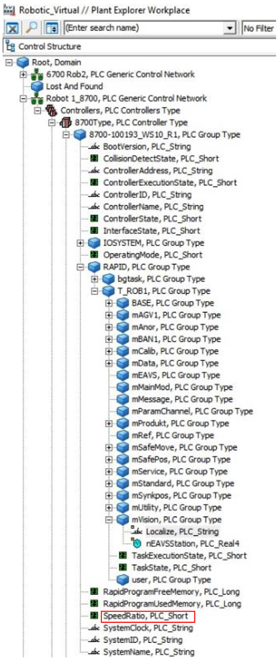
Robot controller structure view in the 800xA system.
Comparison study of the proposed solutions compared to the SOTA
In order to better analyze the proposed approaches in this article, we performed a comparison study to show the features compared to state of the art approaches. In this study, we focus on three ongoing research in the area of smart manufacturing, including McCormick research on developing operating system for cyber physical manufacturing (http://ampl.mech.northwestern.edu/research), The RoboEarch (http://roboearth.ethz.ch/), and the KUKA Robotics project (https://static.kuka.com/).
The main idea behind developing an operating system for cyber physical manufacturing is to leverage discrete-event systems to be able to manage the resources in manufacturing. The operating system consists of a network infrastructure to communicate the manufacturing decisions. The system envisions a four-layer structure, where in the lowest layer the hardware and devices are connected using a vitalized layer to the operating system in the third layer. On the top layer, the network layer manages the core communication.
The work proposed by Hunziker et al. 24 consists of a cloud-based engine, known as Rapyuta. The architecture in this model consists of three layers. The server layer is on the top, which holds a database to store several models and data. The data in this database include the information about situations, semantic of data, and data of devices. There is a mid layer implementation within the proposed architecture that provides control for the robots and devices in the lower layer. The control software, communication protocols between servers and devices, and interface to the devices are part of this layer. The lowest layer is composed of hardware and devices, such as robots, that send information to the database in the servers.
Finally, the work by Bischoff et al. 25 presented a platform for robotics manufacturing. The platform in this proposal contains, again, several layers where KUKA connect and KUKA control panel are the main components. KUKA connect is a cloud-based system, which is responsible to distribute the robot information digitally to any user interface. In this platform, the communication is done with a Transparent Layer Security (TLS) to ensure the security issues when communicating to the cloud. This is in contrast to the proposals in this article where the OPC UA protocols are responsible for the security assessments.
In general, the communication infrastructure in this proposal is based on OPC UA where security protocols are enhanced and embedded, whereas in other cited approaches communication infrastructure is different and in most cases is based on the web-socket framework. In addition, the database within this proposal is created in a sever within the local area network (LAN), while the other approaches can implement cloud-based services, yet without proper consideration of security and privacy issues. While the components are different in the cited approaches, the main architectures are layered-based, which makes the development and engineering of the systems easier.
Conclusion and future work
This article proposed an architecture based on the CPAS technology to be used for DM domains. We proposed a base architecture, then we investigated multiple alternatives to enable communications within the proposed architecture. We presented the advantages and disadvantages of each and every alternative. Moreover, we presented an example from an ongoing project within Production 2030 in Sweden to show the applicability of the proposed alternatives. The significance of this work is to consider legacy components while adapting this technology for DM domain. The future work aims at performing a set of experiments in the implemented systems to show the performance of the proposed alternatives, including the response times in communications, utilization in communications, and security metrics.
Footnotes
Appendix 1
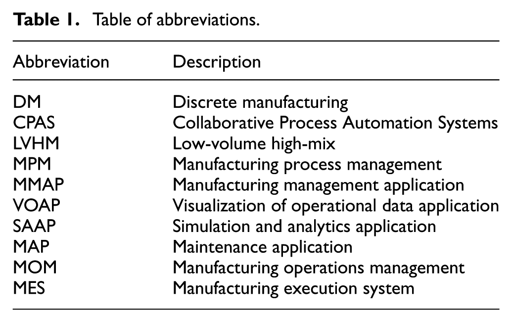
Table of abbreviations.
| Abbreviation | Description |
|---|---|
| DM | Discrete manufacturing |
| CPAS | Collaborative Process Automation Systems |
| LVHM | Low-volume high-mix |
| MPM | Manufacturing process management |
| MMAP | Manufacturing management application |
| VOAP | Visualization of operational data application |
| SAAP | Simulation and analytics application |
| MAP | Maintenance application |
| MOM | Manufacturing operations management |
| MES | Manufacturing execution system |
Acknowledgements
This research has been performed with support from Swedish Governmental Agency for Innovation Systems (VINNOVA) in PADME project. Also, this work was performed in the context of XPRES framework at Mälardalen University.
Handling Editor: Yong-Shin Kang
Declaration of conflicting interests
The author(s) declared no potential conflicts of interest with respect to the research, authorship, and/or publication of this article.
Funding
The author(s) received no financial support for the research, authorship, and/or publication of this article.