
Abstract
Under the guidance of industry 4.0, peoples pay more attention to the intelligent equipment and system. Intelligent vessel without crew on board has acquired growing attention worldwide over the years. The navigation condition of intelligent vessel without crew at sea should be monitored and controlled by the shore-based intelligent vessel support system. The navigation-related data collected by the multi-source navigation sensors should be presented on the shore-based support system in an efficient and friendly way. This article presents a simulation model for multi-source navigation sensors such as echo sounder and electronic position-fixing system. Furthermore, this work proposes an efficient architecture for the shore-based support system by way of multi-source navigation sensors simulation. The results show that the simulation model of multi-source navigation sensors is efficient for the simulation of echo sounder and electronic position-fixing system. The shore-based intelligent vessel support system based on multi-source navigation sensors simulation can present navigation-related data and monitor the condition of intelligent vessel at sea.
Keywords
Introduction
The project of industry 4.0 1 is put forward by German government at Hannover Messe in April 2013. The project is used to prompt the whole level of the automation and computerization. The project of industry 4.0 aims to create a production mode and factory which supply a very flexible, individual and digital product and service. It can be called as smart factory. The cyber-physical system can establish a virtual world through monitoring and copying the realistic physical processes within the smart factory. Except that, the decentralized decisions can be made by the cyber-physical in the virtual world. Under the guidance of industry 4.0, peoples pay more attention to the intelligent vessel without crew over the years. At the 99th meeting of the Maritime Safety Committee (MSC), International Maritime Organization (IMO) formally announced that it would study and formulate relevant conventions and regulations to solve a series of problems such as safety, security, and environmental protection of the Maritime Autonomous Surface Ship (MASS). It means that research on the intelligent vessel is speeding up beyond expectations.
The intelligent vessel system consists of three parts: autonomous navigation system, maritime communication system, and shore-based support system. At present, most of research of intelligent vessel focuses on autonomous navigation system and maritime communication system. HC Burmeister et al. 2 introduce the IMO’s e-Navigation project which aims to enhance safety of navigation by improving ship-to-shore cooperation and the Europe’s Maritime Unmanned Navigation through Intelligence in Networks (MUNIN) project which aims to develop a concept for an autonomous dry bulk carrier. OJ Rodseth 3 reports the MUNIN concept of unmanned merchant ships and the current research activities in Norway. Rolls-Royce develops a virtual prototype of unmanned ship, and announces the Advanced Autonomous Waterborne Applications (AAWA) plan. 4 A concept of shore-based operation control center for remote monitoring of unmanned vessel is proposed. NS Son et al. 5 develop an autopilot algorithm and a fuzzy algorithm to calculate the collision risk for the autonomous navigation system of a small unmanned observation ship. OJ Rodseth et al. 6 introduce a maritime communication architecture with sufficient redundancy and backup solutions between unmanned merchant ship and shore control center.
The essential contribution of this article is that an efficient shore-based intelligent vessel support system is proposed and constructed by way of multi-source navigation sensors simulation. First of all, this article presents a simulation model for multi-source navigation sensors such as echo sounder and electronic position-fixing system (EPFS). The sediment interface and sediment volume backscattering model is built to simulate the echo signal intensity of the echo sounder sensor. The noise distribution model is built to generate the noise simulation of the echo sounder sensor. The algorithm of transformation of coordinate systems is employed to realize the simulation of EPFS sensor. Furthermore, this work proposes an efficient architecture for the shore-based intelligent vessel support system by way of multi-source navigation sensors simulation. The shore-based intelligent vessel support system based on multi-source navigation sensors simulation can present navigation-related data and monitor the navigation condition of intelligent vessel at sea.
The structure of this article is organized as follows: section “Related work” provides a literature review on the intelligent vessel and the multi-source navigation sensors simulation; section “Methodology” describes the problem statement and mathematic model for multi-source navigation sensors simulation; section “Result analysis and discussion” presents the simulation results of multi-source navigation sensors and the efficient architecture for the shore-based intelligent vessel support system; and section “Conclusion and future work” provides the conclusion and direction for future research.
Related works
In this section, we provide a literature review on the research of the intelligent vessel and multi-source navigation sensors simulation. The multi-source navigation sensors refer to echo sounder and EPFS sensor in this article.
MG Jeong et al. 7 propose a multi-criteria route planning technique for operators to objectively determine the routes according to their intentions. The technique can be used for the smart navigation and the future autonomous navigation. Z Zeng et al. 8 propose a distributed shell-space decomposition (DSSD) scheme for rendezvous trajectory planning of multiple autonomous marine vehicles. Z Du et al. 9 propose an approach for motion planning based on Trajectory Unit on a small scale area for unmanned surface vehicle. The planning route can avoid obstacles and meet the movement characteristics of an unmanned surface vehicle.
DD Sternlicht et al. 10 provide a time-dependent model which refers to the acoustic intensity when the energy of ultrasonic wave is backscattered by the seafloor. The characteristics of the echo sounder which refer to transmitting pulse, energy spreading, and absorption losses in the water can be described by the model. The Helmholtz-Kirchhoff theory is employed to predict the energy scattering by the water-sediment interface. PD Mourad et al. 11 create the models of acoustic bottom reflection and backscattering. The frequency of the acoustic wave ranges from 10 to 100 kHz. The data derived from the models are compared with the experiment data from sites with different sediment types. The Rayleigh reflection coefficient is adopted in the reflection model. The result indicates that the data derived from model agree well with experimental data generally. V Murino et al. 12 do some research in the acoustic acquisition systems. The three-dimensional (3D) scene of short range is reconstructed by way of the data processing techniques. It establishes the techniques and algorithms for acoustic image generation and processing. A Ma et al. 13 generate a high-frequency computer image by way of simulating the sound shadow and reflection. Considering the range between two targets and sound reflection, 3D space is built with the Open Graphics Library (OpenGL) by simulation of sonar beam. The result indicates that this method can improve the reality of the simulation greatly. D Chen et al. 14 simulate the SKIPPER GDS101 echo sounder. It studies the key technology to realize the echo sounder simulation of function and interface. The seabed echo and the speckle noise generation are introduced in the article. Bitmap button and knob algorithm are described in the interface part. D Li et al. 15 study the spatial correlation of sea-bottom backscattering for correlation sonar. Based on the characteristics of correlation sonar, the model view controller (MVC) design pattern is proposed to build the simulation system of sea-bottom backscattering for correlation sonar. The simulation software is implemented. M Yao and Yin 16 focus on the simulation of shoal echo and seabed echo, and provide a reasonable simulation model for shoal and seabed as well. The article adopts the point mapping approach to reflect echo location information accurately. The gray-level division method based on the intensity of noise and image processing technology is used to improve the echo image quality of fishing sonar simulator. K Ji et al. 17 develop a reasonable model of acoustic echo intensity, and draw the seabed echo images with specified colors automatically according to echo intensity. AJ Holmin et al. 18 explore on a noise estimation and modeling method. The multiple beam sonar data are used to present the noise which refers to the magnitude, spatial correlation, and probability distribution. The individual acoustic sample which facilitates compensation and subtraction of noise are considered in the method. S Li et al. 19 design a kind of sounder simulator. It consists of signal generator and display simulator. Water depth information is generated according to EPFS and electronic navigation chart (ENC). Then the data are sent to display simulator through either network or serial port in the format of NMEA0183. The display simulator shows the information about water depth graphically based on OpenGL according to user’s setting. The echo sounder sensor simulation is essential for the shore-based intelligent vessel support system. Therefore, the simulation of echo sounder sensor based on echo intensity and backscattering model should be resolved in order to present the depth data and seafloor echo.
EPFS is a key navigation sensor on board which can supply the essential information to the integrated bridge system for navigation. D Ibrahim 20 provides the details of an EPFS simulator system. The system can simulate an EPFS operation in real time and receive user waypoints and external routes. L Wang et al. 21 design and simulate a global positioning system (GPS)/integrated navigation system (INS) based on loosely coupled GPS/INS integration. J Cheng et al. 22 develop a simulation platform which includes four elements: user interface, EPFS signal simulator (intermediate frequency, IF), civilian (C/A) software receiver, and noise generator. K Li 23 designs a set of simulation of EPFS receiver making use of 8051 single-chip computer. K Zhou et al. 24 introduce the functions, composing principle, designing techniques of training software of simulated EPFS navigator. The design notion and part of techniques can be used for the simulation of the same type of instrument. The EPFS sensor simulation is essential for the shore-based intelligent vessel support system. Thus, the key problems such as the transformation of coordinate systems and algorithm of route planning should be settled down in order to finish the simulation of EPFS sensor.
Methodology
Problem statement
The intelligent vessel without crew on board does not mean that it does not need human beings at all. It should be monitored and controlled by the shore-based support system. The shore-based support system emphasizes the user experience of human operations in design. Therefore, the shore-based support system should supply a similar operation environment with the real vessel. The navigation-related data should be collected by multi-source navigation sensors and presented on the shore-based intelligent vessel support system by way of multi-source navigation sensors simulation. Echo sounder sensor can supply the depth data and seafloor echo. In order to present depth data and seafloor echo on the shore-based intelligent vessel support system, the seafloor echo model and noise distribution model should be built for the echo sounder sensor simulation. EPFS sensor can be used to collect the Coordinated Universal Time (UTC), course over ground (COG), speed over ground (SOG), and position data. Furthermore, the EPFS sensor can be used to register the waypoint and make a route planning. Thus, the algorithm of transformation of coordinate systems should be employed for the EPFS sensor simulation.
Echo intensity model
It is supposed that the pressure contributions from the volume and sediment interface to the total field are not correlated. Therefore, the total echo intensity received at time t can be expressed with equation (1)

where
Sediment interface backscattering model
The sediment interface backscattering cross section can be described with equation (2) according to Kirchhoff approximation

where


where
The total acoustic intensity field backscattered by the sediment interface is expressed with equation (8)
where


where
Sediment volume backscattering model
The sediment volume backscattering cross section can be expressed with equation (11)

where


where
The total acoustic intensity field backscattered by the sediment volume is expressed with equation (17)

Noise distribution model
The background noise of echo sounder is derived from ambient sea noise and ship self-noise. The ship self-noise includes mechanical noise, propeller noise, and fluid dynamic noise. The ambient sea noise is expressed with equation (18). The ship self-noise is expressed with equation (19)


where
The noise distributes on the screen randomly with a wide range. The noise strength and density are affected by the gain setting, time variable gain (TVG) setting, clutter setting, and interference rejection setting. The Rayleigh distribution model is used to describe the noise distribution. The probability density function is expressed by equation (20)
where
Transformation of coordinate systems
The coordinate system of World Geodetic System 1984(WGS-84) is a geocentric coordinate system which is built for GPS. A consistent set of model parameters and constants is adopted to describe the shape and size of the Earth in the coordinate system of WGS-84. In the coordinate system of WGS-84, the Earth’s center of mass is defined as the origin, and Z axis points to the direction of Conventional Terrestrial Pole (CTP) defined by Bureau International de l’Heure (BIH) 1984.0. The X axis points to the intersection of 0°meridian of BIH 1984.0 and CTP equator. The Y axis is in accord with right-handed coordinate system.
The coordinate system of WGS-84 is compatible with the International Terrestrial Reference System (ITRS), which is widely adopted internationally. However, different coordinate systems may be used on board for special situation. The coordinate system of EPFS should be adjusted to be consistent with the chart for navigation or position fixing. Therefore, the intelligent vessel should present the position data that can be converted under different coordinate systems.
Suppose that the offset of origin in different coordinate systems is


where


where
The latitude and longitude in the new original coordinate can be obtained by way of equation (27)

Simulation structure
The virtual intelligent vessel is built as a platform of the shore-based intelligent vessel support system. All simulated multi-source navigation sensors are embedded in the virtual bridge. The simulated multi-source navigation sensors can receive and present the navigation-related data from the intelligent vessel at sea. The virtual bridge can monitor the navigation condition of intelligent vessel by way of multi-source navigation sensors simulation.
The modularization method is employed in multi-source navigation sensors simulation for the shore-based intelligent vessel support system. The simulation structure can be divided into several parts, and every part can realize independent function. All parts work together as a whole when the simulated multi-source navigation sensors run. For example, when the auto mode is adopted in the operation of simulated echo sounder sensor, the value of range and gain will be adjusted automatically to display the seafloor and the depth value on the screen.
The simulation of multi-source navigation sensors is designed for two parts: the simulation of interfaces and simulation of functions. The simulation of interfaces refers to the simulation of control panel and buttons. The simulation of control panel and buttons is developed according to the real equipment so that the visual realistic and operation realistic effect can be fulfilled. The mechanism of double buffer is adopted in the simulation of interfaces. The pictures of real equipment are processed first. When the different messages are received, the different pictures are read to the buffer, so that the effect of power on or power off and the effect of button up or button down can be realized. The simulation of functions is the key for the simulation of multi-source navigation sensors. It can affect whether the shore-based officer can monitor and operate the simulated sensors correctly or not.
Result analysis and discussion
Generation of seafloor echo and noise
The quality of generation of seafloor echo affects the realistic effect of display screen under the condition of power on. The simulation of seafloor echo is decided by two parts: the signal intensity of seafloor echo and the range of seafloor echo. The echo signal intensity can be expressed with the sediment interface and sediment volume backscattering model. The noise distribution model is employed to generate the noise under different gain settings on the echo sounder.
The depth data of seafloor echo can be calculated according to nautical chart data if the depth data from real vessel is not available. The depth data and bottom material from the nautical chart are used to create the database of echo sounder. Through calculating the point of intersection between ultrasonic beam and triangle of seafloor, the closest point is selected to draw the seafloor echo on the screen after the coordinate transform. Figure 1 demonstrates the calculation of seafloor echo. The triangle UVW is the triangle of seafloor, and the line MB is the simulated ultrasonic line which direction vector is


Calculation of depth data.
The unit normal vector


The point of intersection
The generation results of seafloor echo and noise (Gain = 4) are shown on the simulated echo sounder sensor in Figure 2. The echo signal intensity is generated by way of the sediment interface and sediment volume backscattering model. The noise is simulated with the noise distribution model under different gain settings. The depth data of seafloor echo are derived from the nautical chart data. The simulation results indicate that the seafloor echo and depth data can be shown on the shore-based intelligent vessel support system effectively.

Simulation results of seafloor echo and noise (Gain = 4).
Display mode of echo sounder sensor simulation
In order to avoid intelligent vessel grounding, the shore-based officer should monitor and operate through the echo sounder sensor simulation. Thus, the display mode of echo sounder sensor simulation should be same to the real sensor equipped on the intelligent vessel. The FURUNO FE-700 echo sounder sensor is adopted in the current research.
The FURUNO FE-700 echo sounder has seven normal display modes. It includes navigation mode, depth below surface mode, history mode, logbook mode, own ship data mode, help mode, and main menu mode. Except the seven normal modes, the extension mode can be accessed if any button is pressed together with the power button before turning on. In order to realize the simulation effect of pressing two buttons by one mouse, the icon is used in the programming. The cursor of mouse changes into two hands when the mouse right clicks the control panel. Hand icon is drawn on the button when the mouse left clicks the button of DRAFT or MUTE ALARM, DIM or BRILL, AUTO or COLOR, or – or +.
The development platform of visual studio 2017 is employed to simulate the FURUNO FE-700 echo sounder sensor. All the display modes have been simulated as the real echo sounder sensor equipped on the intelligent vessel. The simulation results of depth below surface mode and own ship data mode are show in Figure 3. The interface and operation in Figure 3 are same to the real echo sounder sensor. The simulation results of echo sounder sensor are satisfied for the shore-based officer. It has been used to present the depth data and avoid intelligent vessel grounding. The simulated echo sounder sensor has been embedded on the virtual bridge of shore-based intelligent vessel support system to monitor the navigation condition of intelligent vessel.
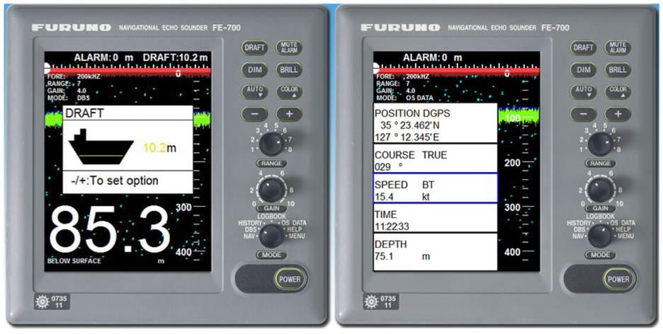
Simulation results of different display modes of echo sounder sensors.
Route planning of EPFS sensor simulation
EPFS is a key navigation sensor on board which can supply the essential information (e.g. UTC, COG, SOG, and Position) to the intelligent vessel. Furthermore, the EPFS sensor can be used to make a route planning for the navigation of intelligent vessel.
The waypoints are essential elements to navigate the intelligent vessel by way of EPFS sensor. The simulation of route planning function is dependent on the waypoint setting. Therefore, the calculation based on waypoints is very important for EPFS sensor simulation. The great circle track is the closest way between two waypoints on the earth. Therefore, the calculation on waypoints and routes is based on the great circle track. Usually, there are three methods to calculate the great circle, such as great circle chart method, arc to chord correction method, and formula computation method. The formula computation method is suitable for programming, so that it is adopted in the EPFS sensor simulation.
It is assumed that the latitude of starting waypoint is


where

Route planning must be done before using the EPFS sensor to navigate the intelligent vessel. Therefore, the route planning is a key module in the simulator of EPFS sensor. The formulas of great circle track are adopted to calculate the certain trip between two waypoints. The total trip can be got through accumulation. According to vessel’s speed, the parameter of Time to go (TTG) can be calculated.
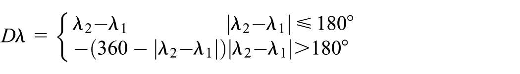
Suppose the latitudes and longitudes of two waypoints are known as


where

where
The development platform of visual studio 2017 is employed to simulate FURUNO GP-150 and JRC JLR-7700MKII EPFS sensors. The simulation results of FURUNO GP-150 EPFS sensor are shown in Figure 4. The waypoints no. 001 and no. 002 are selected to make a navigation route in the simulation. Through calculating, the trip between the two waypoints is 600 nautical miles. If the vessel’s speed is 10.0 knots, the TTG between two waypoints can be calculated as Figure 4. The simulation results of JRC JLR-7700MKII EPFS sensor are shown in Figure 5. The waypoints no. 001 and no. 003 are selected to make a navigation route in the simulation. The bearing and trip are calculated between the waypoints 001 and 002. The interface and operation in Figures 4 and 5 are same to the real EPFS sensor. The simulated EPFS sensors have been embedded on the virtual bridge of shore-based intelligent vessel support system to make the route planning for the navigation of intelligent vessel.

Simulation results of route planning of FURUNO GP-150 EPFS sensor.

Simulation results of route planning of JRC JLR-7700MKII EPFS sensor.
Shore-based intelligent vessel support system
The intelligent vessel system consists of three parts: autonomous navigation system, maritime communication system, and shore-based support system. The architecture of shore-based intelligent vessel support system proposed in this article is shown in Figure 6. The shore-based support system is responsible for remote monitoring of autonomous navigation system and provides information support for intelligent vessel decision-making. The autonomous navigation system is equipped on the real vessel. The real vessel can navigate on the sea by way of autonomous navigation system. If the autonomous navigation system is not available, the real vessel can navigate on the sea under the control of shore-based support system. The maritime communication system is used to exchange the information between the real vessel and shore-based support system.

The architecture of shore-based intelligent vessel support system.
This article developed a virtual intelligent vessel as the platform of shore-based intelligent vessel support system. The multi-source navigation sensors are simulated according to the navigation-related data collected by the real vessel. All the simulated multi-source navigation sensors are embedded on the platform of virtual intelligent vessel. Thus, the shore-based officers can monitor the real vessel at sea by way of the multi-source navigation sensors simulation. The operation order on the multi-source navigation sensors simulation can be transmitted to the real vessel through the maritime communication system.
The 3D development platform of Unity3D is used to develop the virtual intelligent vessel. The 3D interactive operation on the virtual intelligent vessel is realized by the HTC VIVE helmet and controller. The virtual intelligent vessel with the simulated multi-source navigation sensors is realized based on the vessel of “Chang Shan Hai.” The virtual bridge of shore-based intelligent vessel support system developed by our research group is shown in Figure 7. The virtual intelligent vessel “Chang Shan Hai” with 3D interaction developed by our research group is shown in Figure 8. The shore-based officer can check the navigation condition of virtual intelligent vessel by way of 3D head-mounted display (HMD) system. The operation on virtual intelligent vessel can be done with the controller. The course control order can be given by way of the rudder in the virtual bridge. The speed control order can be given through the engine telegraph in the virtual bridge. The simulated echo sounder sensor in the virtual bridge can present the seafloor echo and depth data to avoid the real vessel grounding. The simulated EPFS sensor can present the related data (e.g. Position, COG, SOG, and UTC) to monitor the position and navigation condition of the real vessel. The operation of waypoint setting and route planning can be done on the simulated EPFS sensor. Then, the information of waypoint and route can be transmitted to the autonomous navigation system. The intelligent vessel at sea can navigate to the destination according to the waypoint and route information. It indicates that the architecture proposed in this article is reasonable and effective. The virtual intelligent vessel platform developed by our research group can meet the requirements of shore-based intelligent vessel support system.

The virtual bridge of shore-based intelligent vessel support system.

The virtual intelligent vessel platform with 3D interaction.
Conclusion and future work
Through performing research on the simulation of multi-source navigation sensors and shore-based intelligent vessel support system, the contributions of the article can be summarized as follows.
First of all, the simulation models for multi-source navigation sensors such as echo sounder and EPFS are proposed in the article. The sediment interface and sediment volume backscattering model is built to simulate the echo signal intensity of the echo sounder sensor. The noise distribution model is built to generate the noise simulation of the echo sounder sensor. The algorithm of transformation of coordinate systems is employed to realize the simulation of EPFS sensor. The simulations of echo sounder and EPFS sensor are finished based on the simulation model and algorithm.
Furthermore, an efficient architecture for the shore-based intelligent vessel support system is proposed by way of multi-source navigation sensors simulation. The virtual intelligent vessel platform based on the multi-source navigation sensors simulation are developed and tested with the vessel of “Chang Shan Hai.” The architecture proposed in the article is reasonable and effective. The virtual intelligent vessel platform can meet the requirements of shore-based intelligent vessel support system.
Except the multi-source navigation sensors, the marine radar is an important instrument on the bridge to make sure the safety of intelligent vessel. Thus, the radar simulation in the virtual intelligent vessel based on the generation algorithm of radar echo will be carried out in the following research works.
Footnotes
Handling Editor: Hiram Ponce
Declaration of conflicting interests
The author(s) declared no potential conflicts of interest with respect to the research, authorship, and/or publication of this article.
Funding
The author(s) disclosed receipt of the following financial support for the research, authorship, and/or publication of this article: This work was supported by the Natural Science Foundation of Liaoning Province (no. 20170540085), the Fundamental Research Funds for the Central Universities of China (no. 3132019132), the Educational reform of Dalian Maritime University (nos 2017Y05 and 2018Y09), and the Research Funds of China Institute of Communications Education (nos 1802-142 and 1802-300).